16. Interface and application programming
This week’s assignment was to write an application that interfaces a user with the input &/or output device that you made.
To contribute to my final project, I decided to create a UI that updates with the current humidity of the room, to display on my Magic Mirror API. The Magic Mirror API is an open-source program that was interfaced using ELectron. I separately made a UI using python and the Pillow library to create an image, which is then taking the data every second to update the image and its values constantly. I then integrated this into the Magic Mirror API, by writing some javascript in the .config file of the software.
A little more on how the sensor works with the UI.
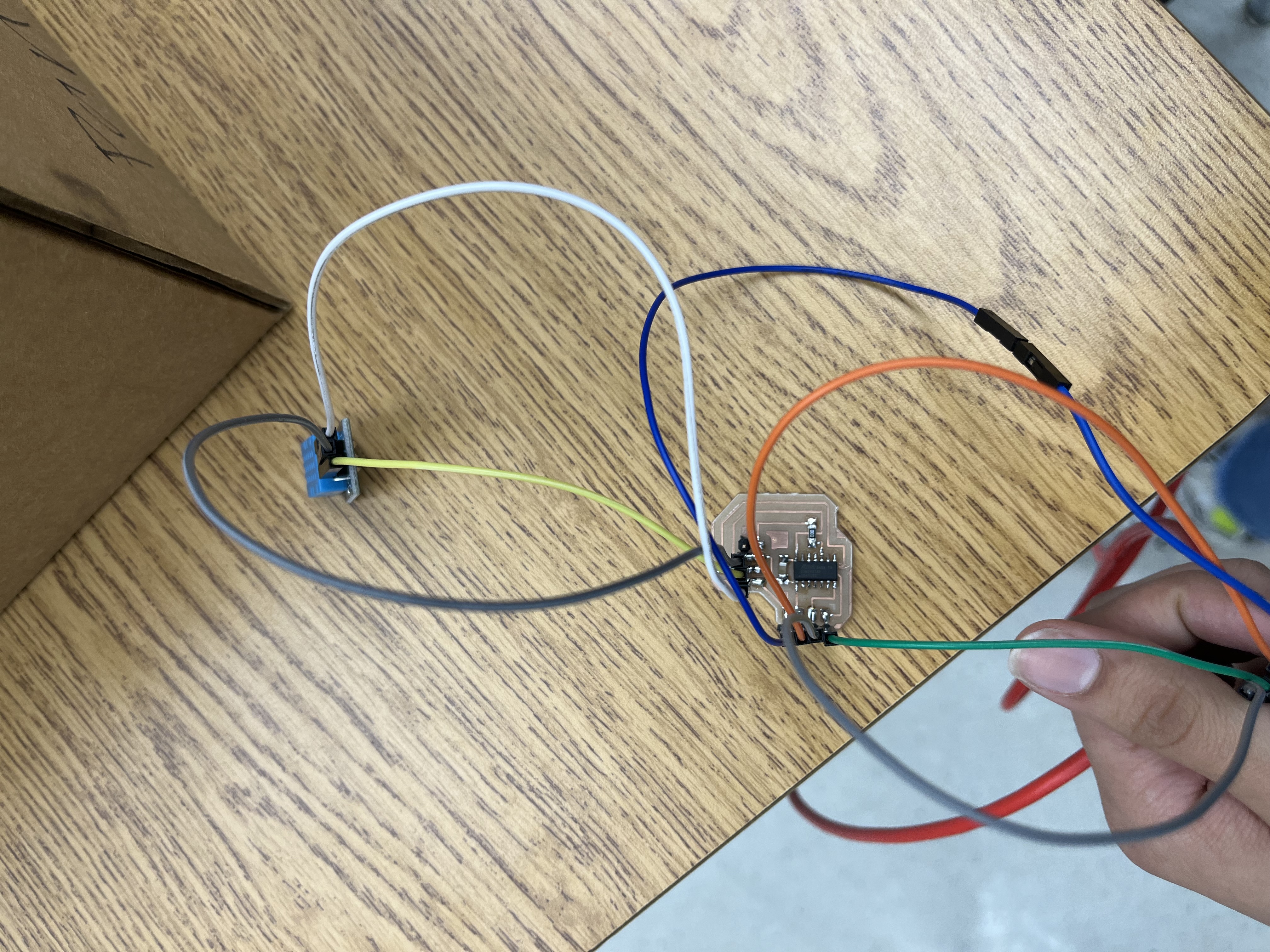
I am using a 1614 board, connected to a DHT11 humidity sensor. This 1614 board is then connected to an FTDI through GRD, VCC, RX, and TX. Since I am using a Raspberry Pi, I plugged my FTDI board into one of the USB ports of the Rasberry Pi. Then I would read serial through that port to get the values of the humidity sensor to show on the Raspberry pi. Once those values had shown, I created a python script using the python image library pillow, which helped me generate a text-to-image, which was constantly updated with values. This is similar to matplotlib; something which is recommended by Dr. Neil and the Fab Academy Site.
So in summary, this is the overview of my Interfacing.
Humidity Sensor (input)—> 1614 Chip (Microcontroller)—> FTDI (Communication over serial)—> Raspberry pi (Uses python to Generate UI by using Serial values).
Here are the filesfor this week
Process to making it
To first make this, I designed a custom PCB board. As I have done in my previous weeks I followed my documentation which is linked here.
Here is the BOM I used to make this board.
BOM
- AtTiny 1614
- Headers (2x)
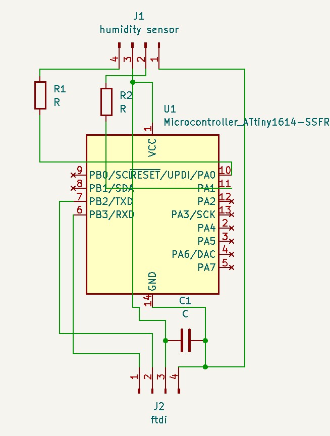
Schematic
I made my schematic on Kicad and followed my documentation for previous weeks on how to do this. This is the week you can refer to as well.
Here is what my schematic looked like:
After designing the schematic, I started to design my PCB Board and started to mill that.
PCB Board
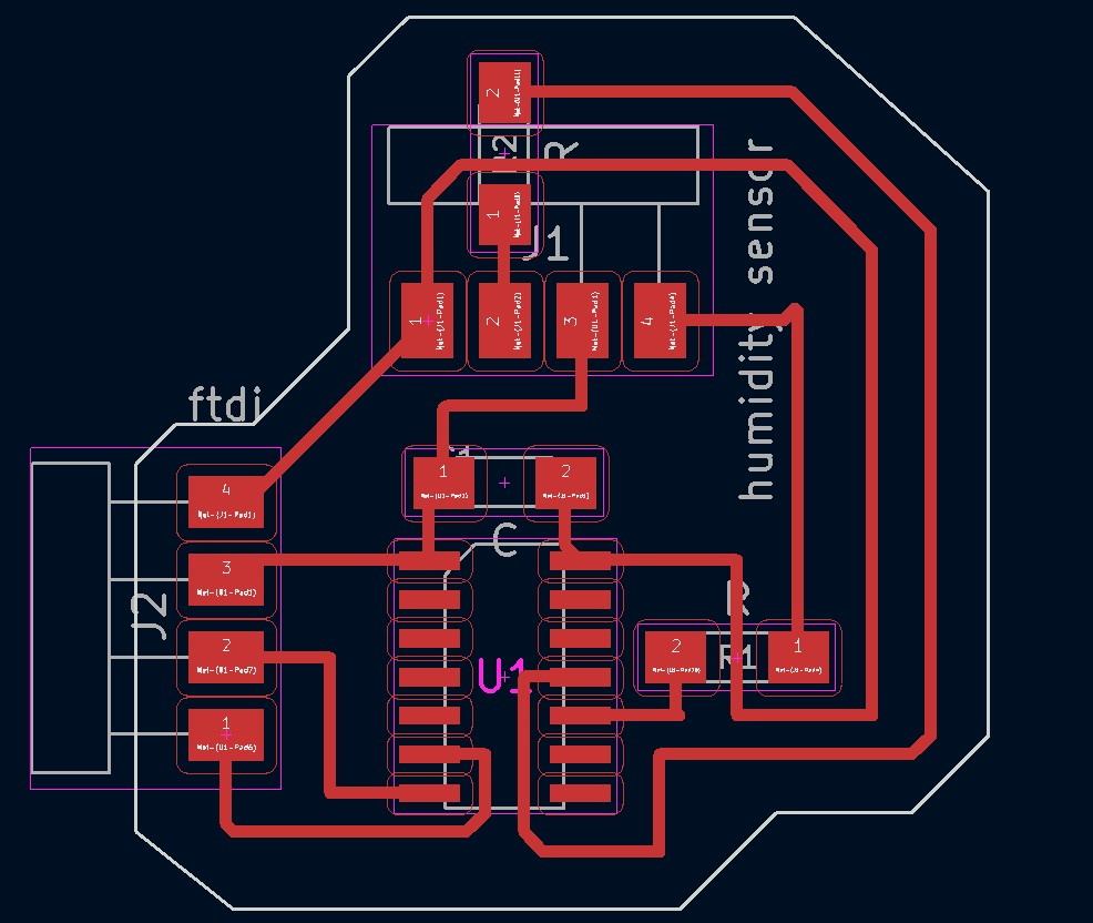
Once the PCB Board was designed, I started to mill it. I followed my documentation from the previous week to guide me in case I get lost. This is the documentation I used.
Milling
By following my previous documentation, I milled my board and sodered on all the components.
Here is a video of me milling my board.
Video Milling
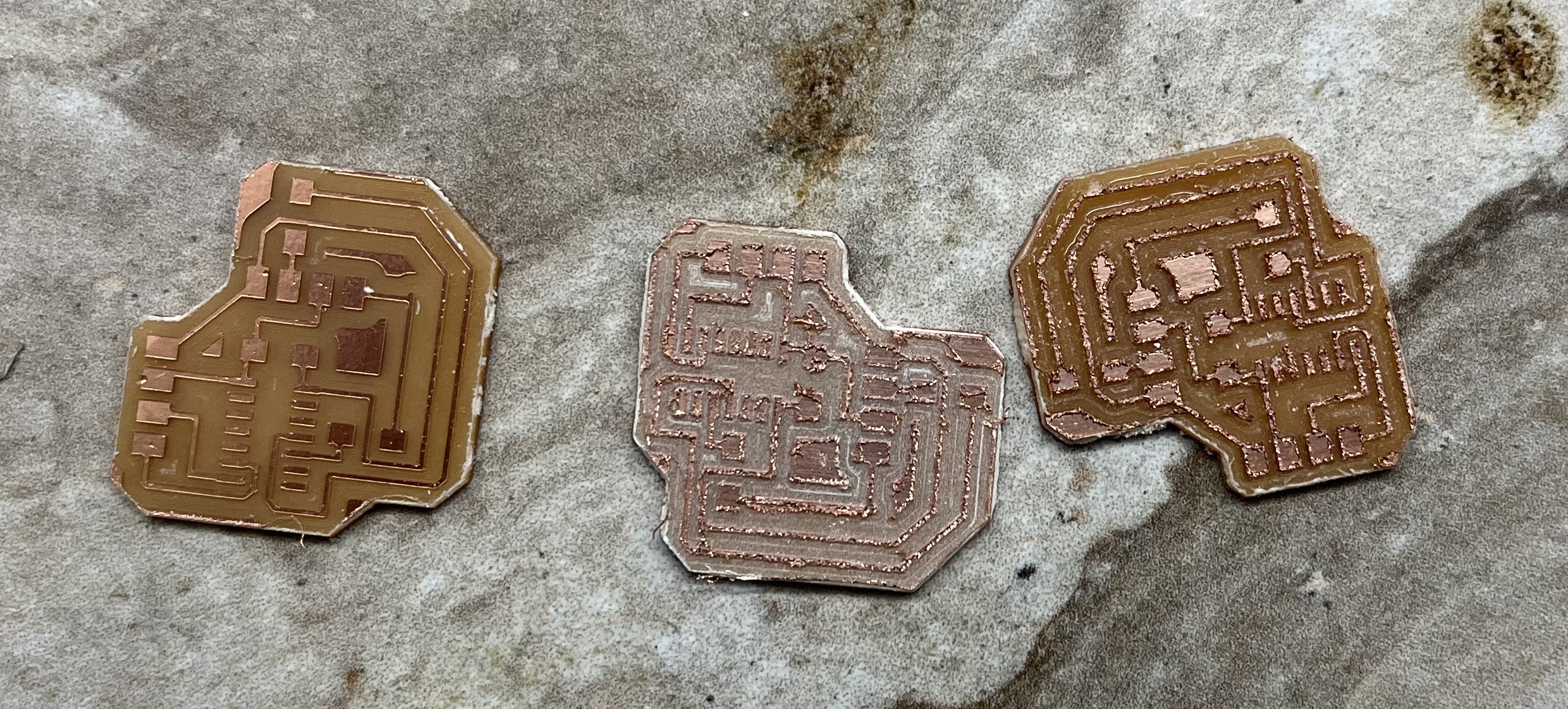
My mill the first 2 times came out super rough because I realized that I had used a bad bit. When I changed my bit and milled again, My board came out perfectly.
Here are the pictures of all the boards that I have milled.
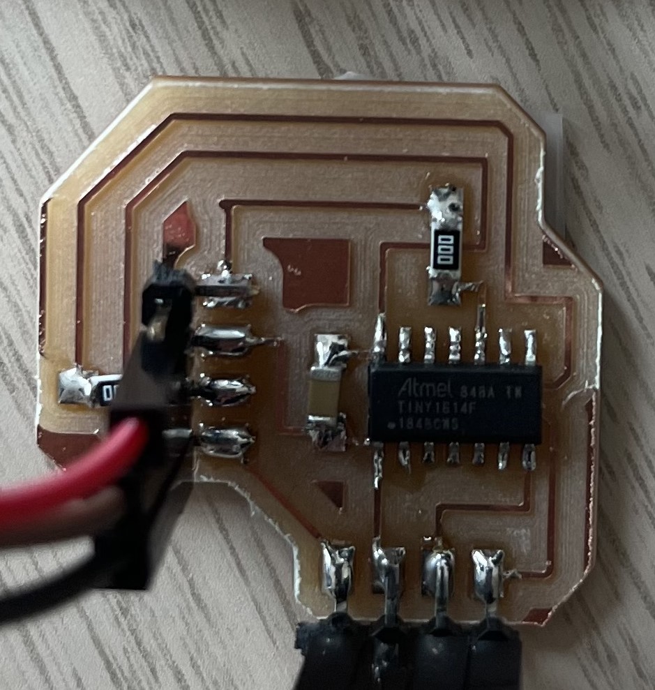
Great, now I sodered all my components together,m so my board now looks like this!
Creating the User Interface
This was one of the hardest things this week, due to my very very limited python experience. That’s right, this is one of my first times coding in Python other than taking an introductory Computer Science class.
To make my user interface, I referred to many websites as listed. I HIGHLY recommend these websites:
How to Generate Text on Image with Python
To create the UI, I first Installed pip install Pillow by opening my terminal and typing it in. This is a whole library that will help me create an environment for my UI. In other words, it is an imaging library. Learn more about Pillow here.
After installing Pillow, I started writing my code to start creating the environment for my UI.
My initial ideas were that I wanted a black background, so it would match the Magic Mirror API background, and I wanted some classy text to display the current humidity in the room.
With this, I started writing my code. I followed this website to first create an example, and then inputted my values and made my modifications.
Here is the code of the example provided:
from PIL import Image, ImageDraw, ImageFont
width = 512
height = 512
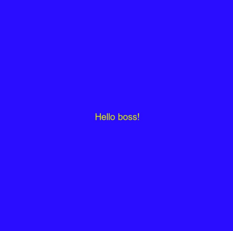
message = "Hello boss!"
font = ImageFont.truetype("arial.ttf", size=20)
img = Image.new('RGB', (width, height), color='blue')
imgDraw = ImageDraw.Draw(img)
textWidth, textHeight = imgDraw.textsize(message, font=font)
xText = (width - textWidth) / 2
yText = (height - textHeight) / 2
imgDraw.text((xText, yText), message, font=font, fill=(255, 255, 0))
img.save('result.png')
After writing this code, I got a picture that looked like this:
Now, I added my variables to design the type of custom UI I wanted.
Here was my code for that:
from PIL import Image, ImageFont, ImageDraw
import Adafruit_DHT
import time
import serial
#inside your I2C/serial code main while loop you created in step 2, where it continuously prints the humidity, replace the "print()" statement with t
#the following and make sure you put in the humidity variable as whatever your I2C code calls it (I don't have your code for this so I have no idea what you have it named).
def readHumidity():
DHT_SENSOR= Adafruit_DHT.DHT11
DHT_PIN=18 #i2c pin or normal pin on RPI?
#Image Starts here
#Dimensions of Picture
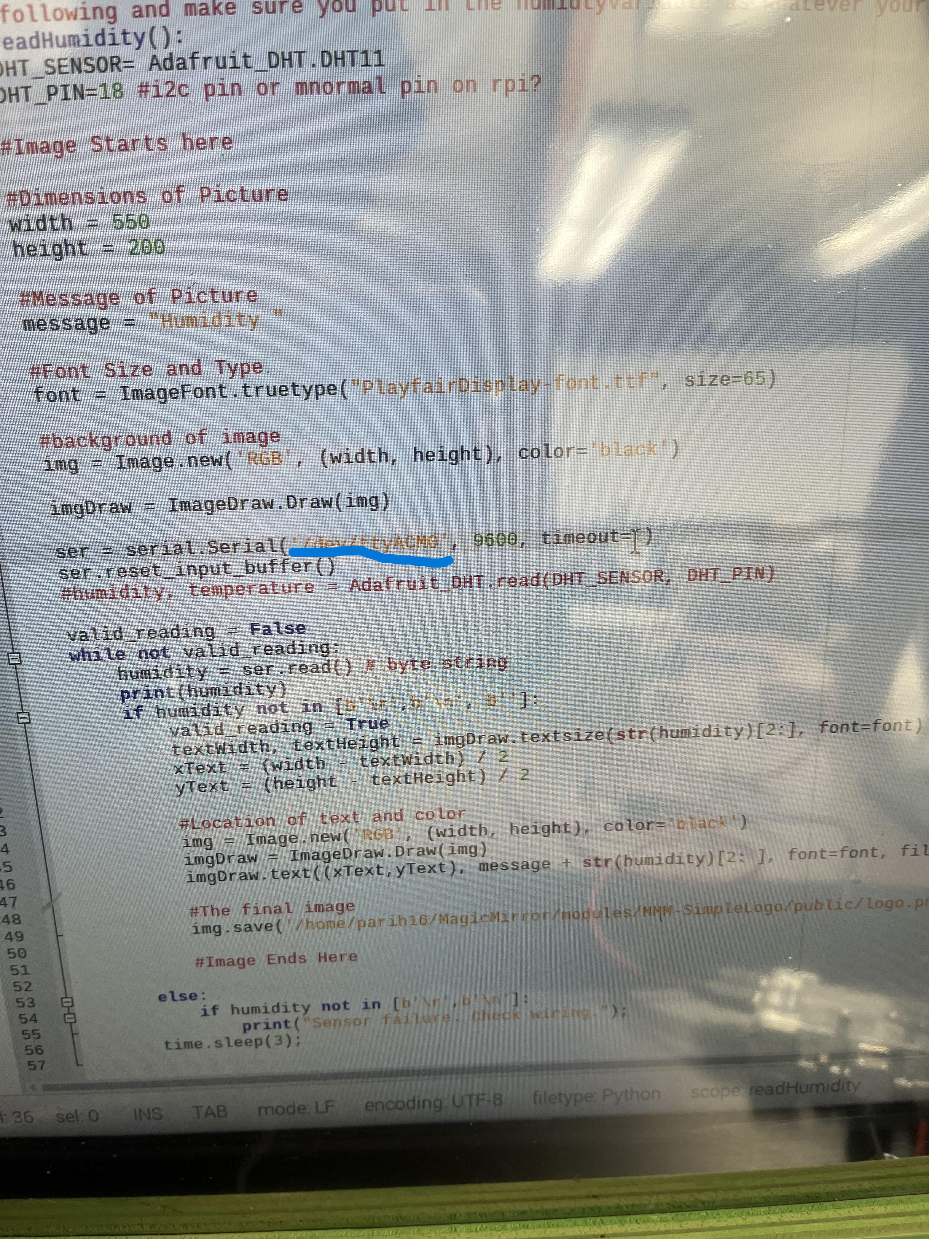
width = 550
height = 200
#Message of Picture
message = "Humidity "
#Font Size and Type
font = ImageFont.truetype("PlayfairDisplay-font.ttf", size=65)
#background of image
img = Image.new('RGB', (width, height), color='black')
imgDraw = ImageDraw.Draw(img)
ser = serial.Serial('/dev/ttyUSB0', 9600, timeout=1)
ser.reset_input_buffer()
#humidity, temperature = Adafruit_DHT.read(DHT_SENSOR, DHT_PIN)
valid_reading = False
while not valid_reading:
humidity = ser.readline() # byte string
print(humidity)
if humidity not in [b'\r',b'\n', b'']:
valid_reading = True
textWidth, textHeight = imgDraw.textsize(str(humidity)[2:], font=font)
xText = (width - textWidth) / 2
yText = (height - textHeight) / 2
#Location of text and color
img = Image.new('RGB', (width, height), color='black')
imgDraw = ImageDraw.Draw(img)
imgDraw.text((xText,yText), message + str(humidity)[2: ], font=font, fill=(255, 255,255))
#The final image
img.save('/home/parih16/MagicMirror/modules/MMM-SimpleLogo/public/logo.png')
#Image Ends Here
else:
if humidity not in [b'\r',b'\n']:
print("Sensor failure. Check wiring.");
time.sleep(3);
As you can see, I changed the background to black and I also changed the font of the text. This code also can read serial from the Raspberry pi Port and update the data every second.
It is through this line ser = serial.Serial('/dev/ttyUSB0', 9600, timeout=1) that I can read the serial from the raspberry pi.
I used this website, which is a very helpful website, as it shows you step-by-step how to read serially from a raspberry pi. Here is the website to check out! I highly recommend it.
I also used another website, which seemed to be even better, and explained everything very clearly. Here is that website to check out.
By using this website, I plugged in my FTDI cable on my Rasberry pi and then went to the terminal and typed
this popped up with multiple different devices to choose from. I knew that my device is going to start with something like ttyACM0. I decided that and copy pasted that into my code:
So it looked something like this:
Once writing this successfully, I moved on to making it look nice and reterive the correct values.
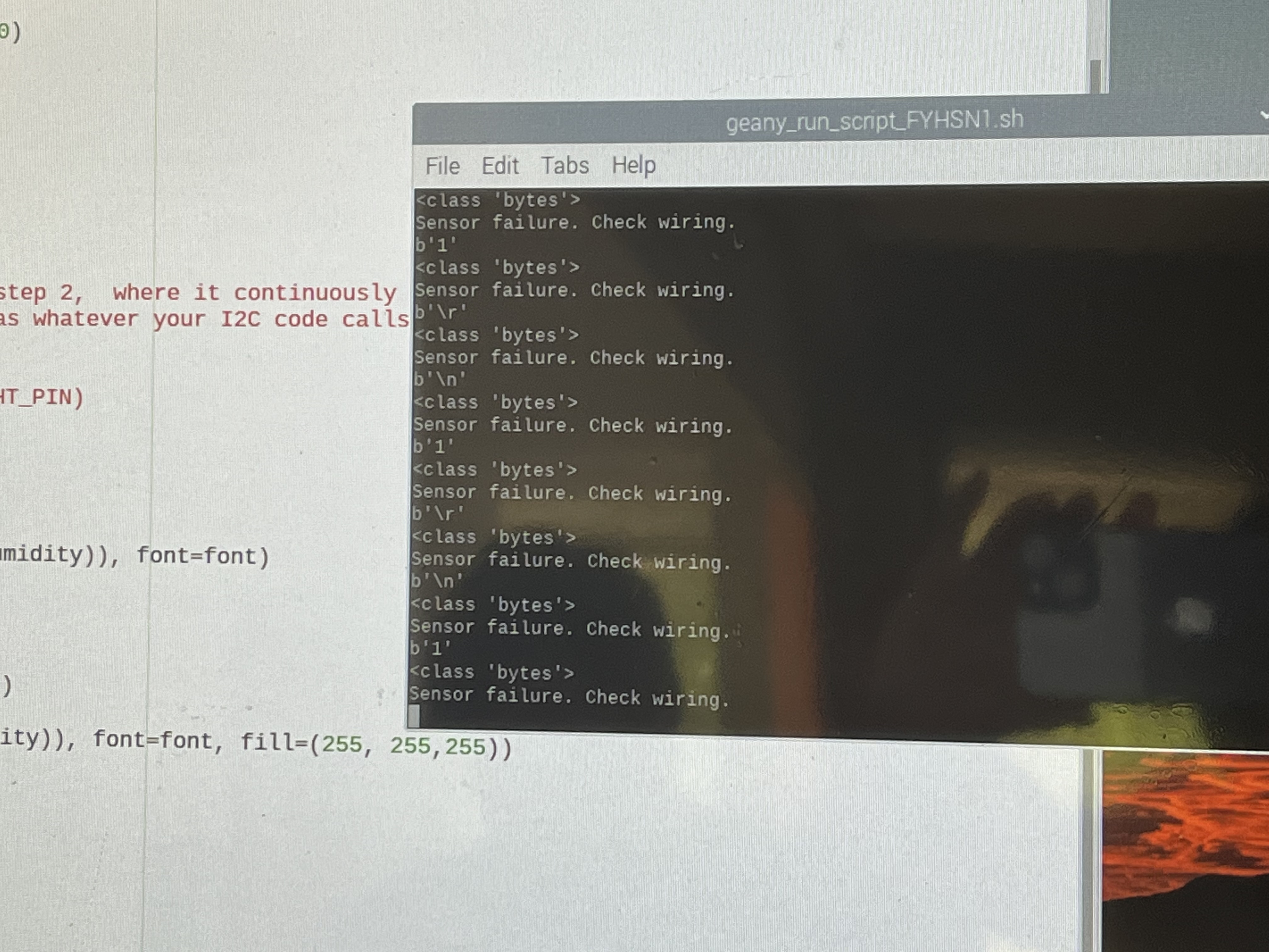
Now It is time to test the UI, to see if I get any values. I first plugged in a DHT-11 Humidity Sensor directly to my Raspberry pi and started getting values. Although these values were not integers, they were bytes. As you can see in the code above, I decided to get rid of the bytes which were coming and just wanted to hone my attention on the integer numbers, but those came as strings and not floats. That was fine although I was also getting random stuff too such as byte strings, new lines, carriage returns, etc. With the help of Adam Durrett, my Computer Science teacher, he suggested that I try to eliminate these random things and make a line such as this one:
if humidity not in [b'\r',b'\n', b'']:
valid_reading = True
textWidth, textHeight = imgDraw.textsize(str(humidity)[2:], font=font)
xText = (width - textWidth) / 2
yText = (height - textHeight) / 2
Printing Bytes and in between
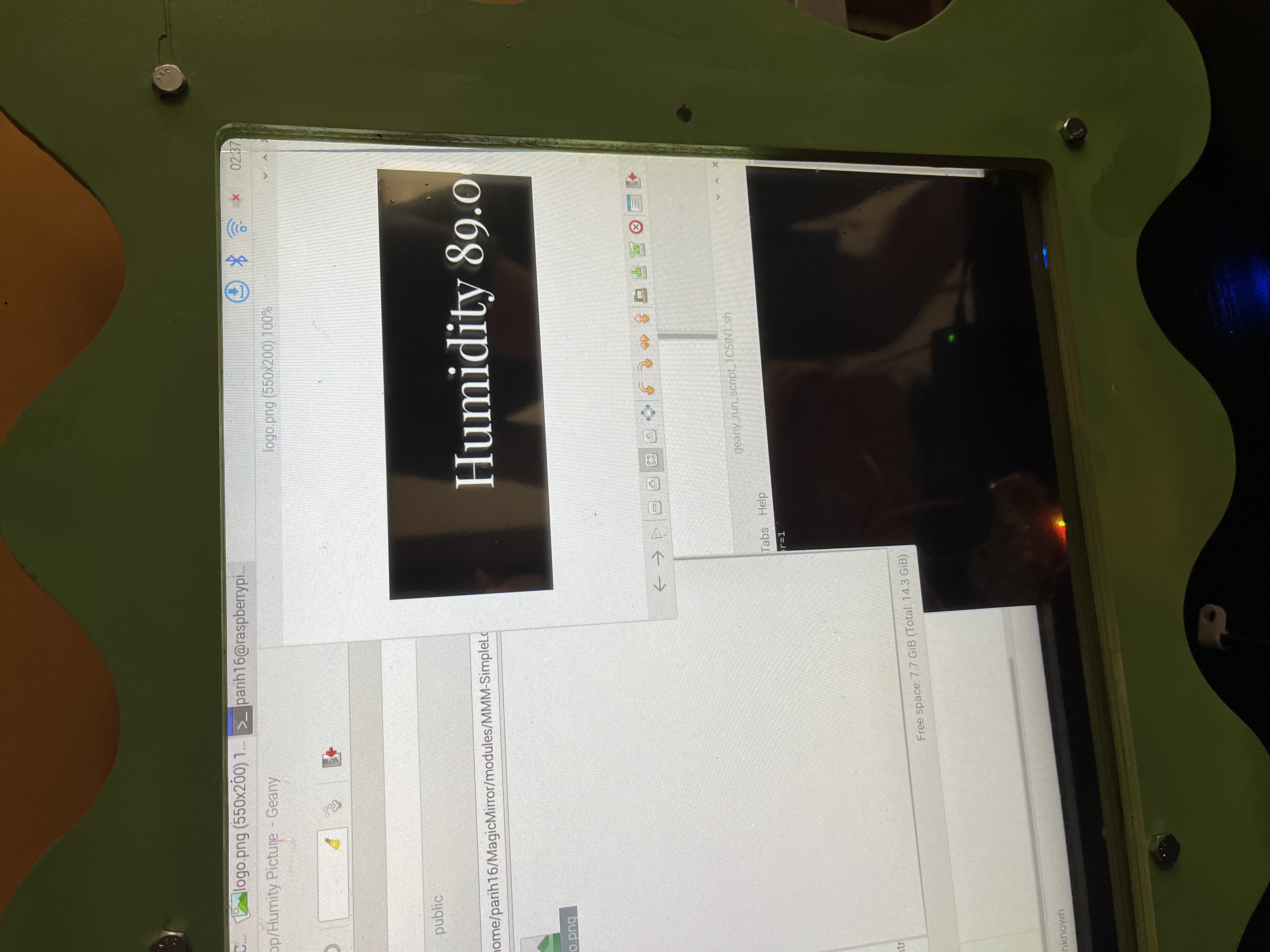
Just printing the String of Numbers (Humidity Values)
Now that the UI is all set, I tried to get the physical components to work.
Programming
Surprising this board was probably, the easiest board I have ever programmed. Everything worked first try, and with my luck sometimes it doesn’t, but it did.
I broke this process up into 2 parts:
Part 1
Upload the Humidity Sensor Code onto the 1614 chip, and make sure that is the first printing to the Arduino Serial Port, by using an FTDI.
Part 2
Now connect FTDI, to the Raspberry pi, and make sure the code is written for the UI, and Raspberry pi works together and displays the live and current values on the Magic Mirror API (making my custom 3rd party module) through Txt to Image on python, just like Tkinter.
Great! Let me show you each detailed step on how I approached this.
Steps for Part 1
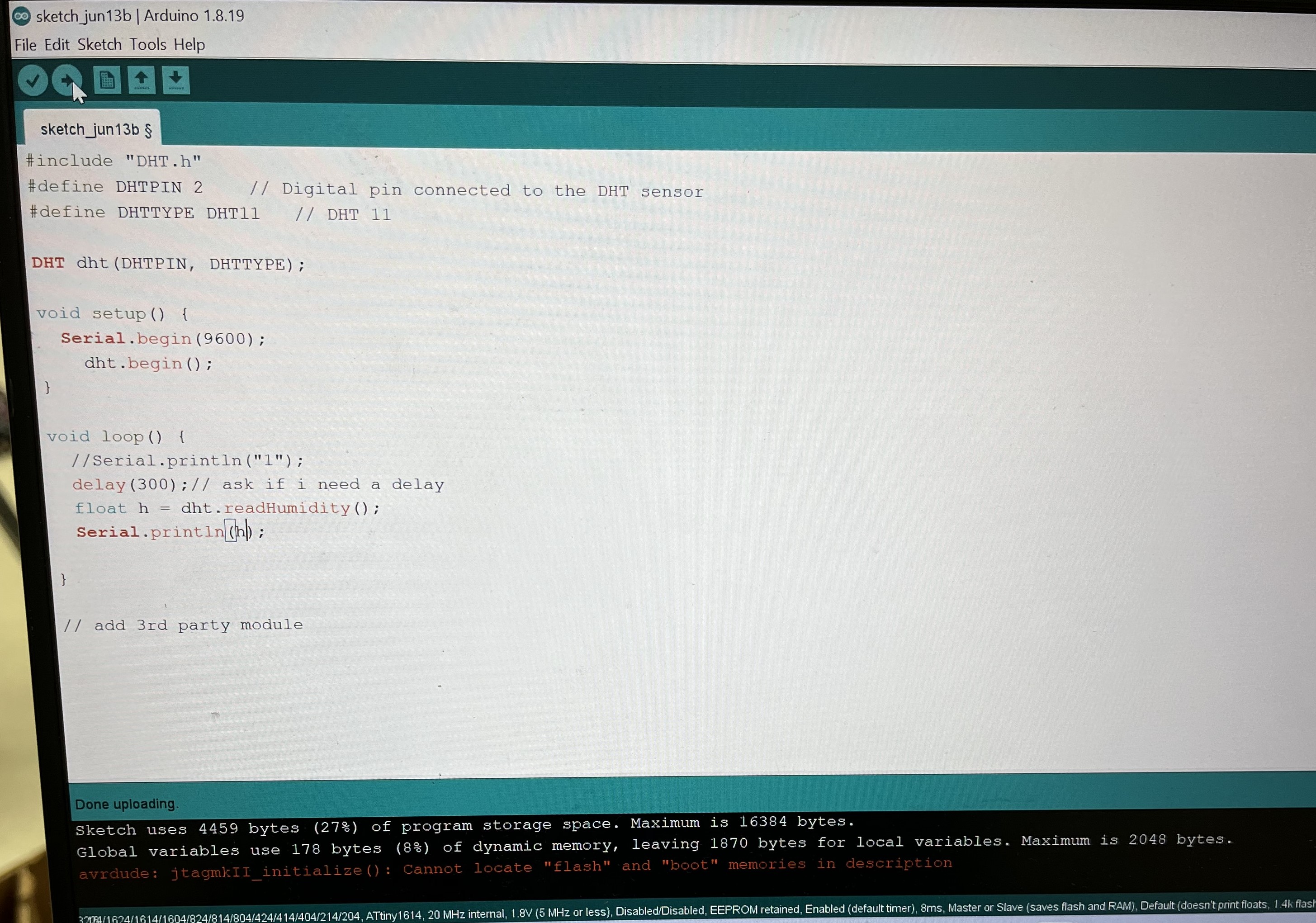
I first opened Ardunio IDE and uploaded this code onto my 1614 chip.
#include "DHT.h"
#define DHTPIN 8    // Digital pin connected to the DHT sensor
#define DHTTYPE DHT11   // DHT 11

DHT dht(DHTPIN, DHTTYPE);

void setup() {
  Serial.begin(9600);
    dht.begin();
}

void loop() {
  //Serial.println("1");
  delay(300);// ask if i need a delay
  float h = dht.readHumidity();
  Serial.println(h);

}

// add 3rd party module
Once this code was uploaded, I moved on to part 2.
Part 2
Part 2 was the last step. After the UI is all set up and Part 1 is complete then we can only come to part 2.
In part 2 we connect the FTDI to the milled board which has the 1614 chip loaded with information. I plugged in the USB cable of the FTDI of my raspberry pi and select the correct device attached to the port. To do this, I have some more explanations above where I created the UI section of this page.
Once all the ports were selected and everything was selected, I decided to test it out. I ran the code, and IT WORKED!!!! I transmitted data from 1614 to a raspberry pi which received my data! This was amazing!
Here is what it looked like:
Making a 3rd Party Module
To make a 3rd Party module was extra credit/ extra work I did which would help towards my final project.
Now that the hard stuff is done, I had to make a 3rd party module. This is so my UI can be shown constantly in my final project. To do this, I first used GitHub to get his logo to show up on my API. By doing this, I would understand how to get a logo onto my mirror, and then how to get my UI to show on the Magic Mirror API.
This was an interesting but easy process. This is the GitHub I used.
)
Here are the steps of how I go this logo to work.
1 . I first cloned his repo
2 . I went to his public file and downloaded the image of his logo.
3 . Once that was downloaded, I went to my Magic Mirror config file and make this another module:
modules: [
    {
        module: 'MMM-SimpleLogo',
        position: 'top_left',    // This can be any of the regions.
        config: {
            // The config property is optional.
            // See 'Configuration options' for more information.
        }
    }
]
It was that simple.
Here is what it looked like:
Once following these steps, I did the same with the humidity UI I created. I moved the file which contained the UI and put it in my Magic Mirror folder. Once it was placed in there, I changed the location of the file with the path of my file.
So it would look something like this:
This line of code is also a part of the code for the UI.
Once I did this my UI finally showed up on my Magic Mirror’s screen. The API itself is run by Electron, which is another platform. interface Dr. Neil recommended us to use.
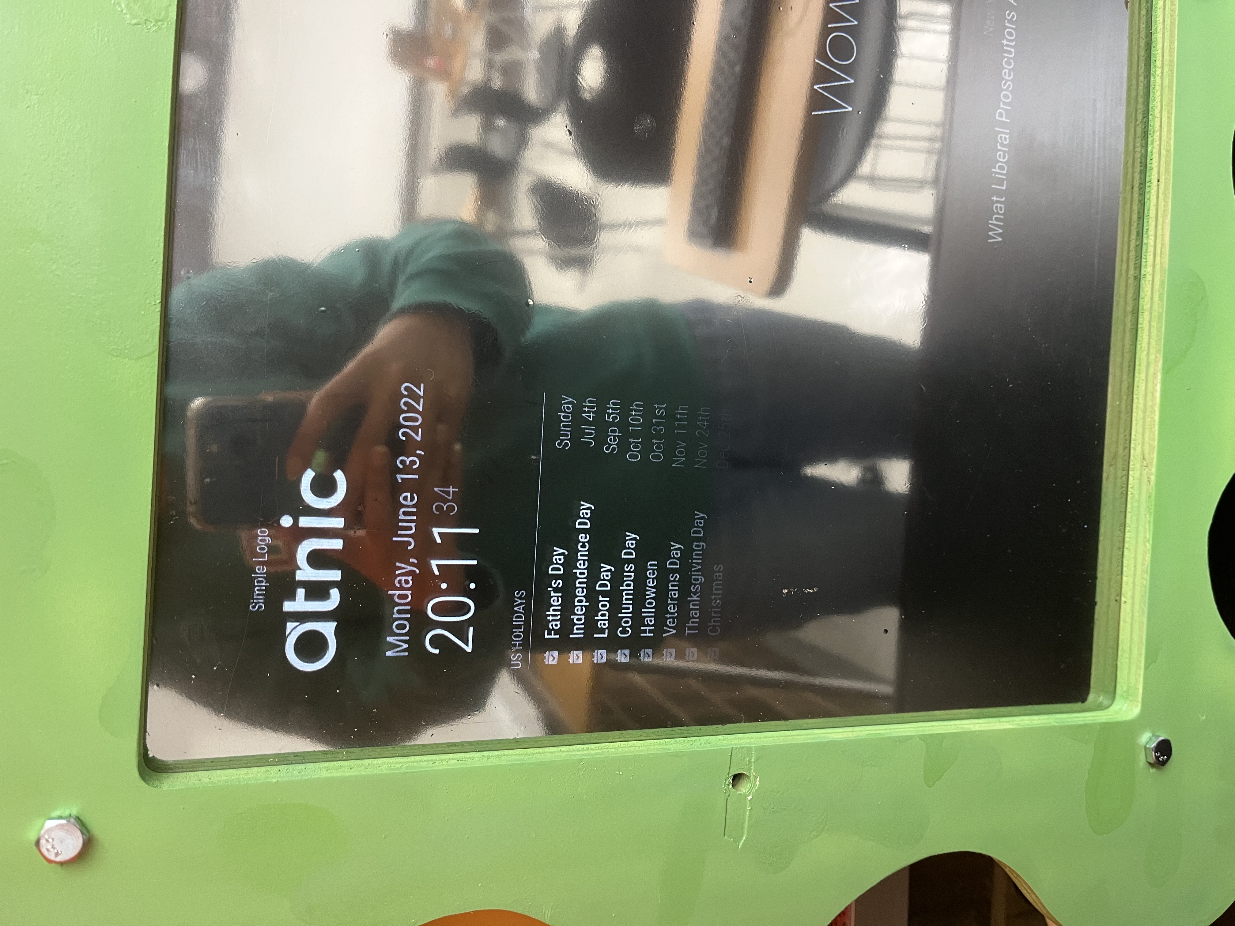
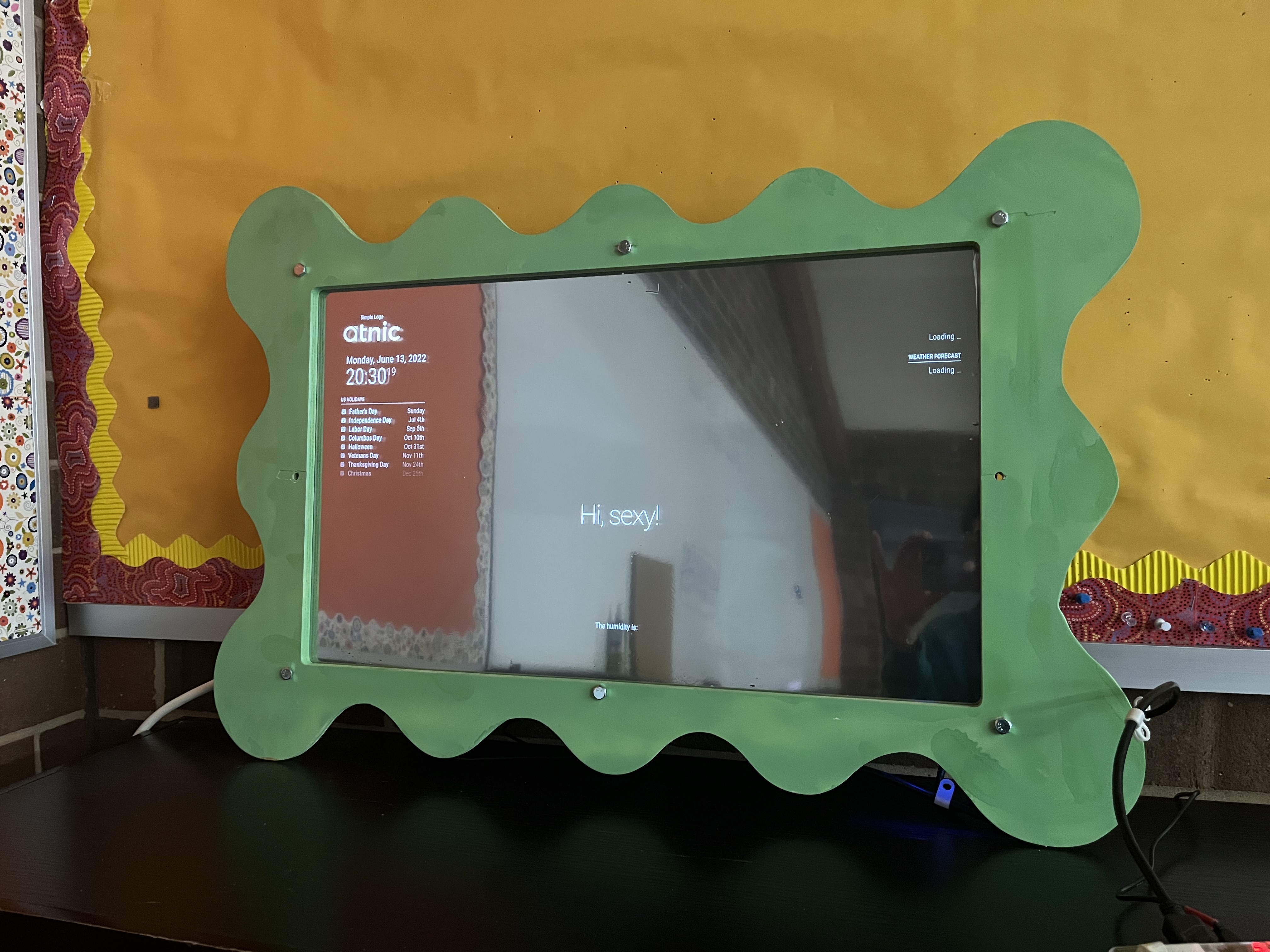
This is what it looked like:
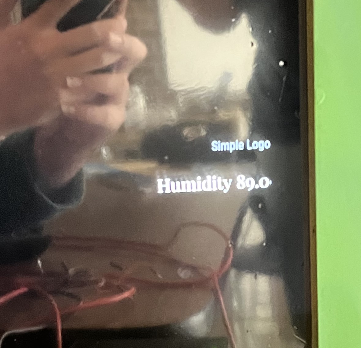
Humidity UI as a 3rd Party Module
Final
Here is some video of my humidity sensor working and transmitting values through an ATtiny 1614 chip using RX/TX to communicate through an FTDI to a Raspberry pi.
Final Video
Summary
This week was fun! I had many successes and learned many new things about Python coding and diffrent libraries. I also learned how to add 3rd party modules to my Magic Mirror. Considering this to be my first time doing this, I am very happy with what I have done.
Group Work
For this week’s group work, I worked with Aaron, Alaric, and Andrew to interface out inputs using different software. I did software similar to Alaric.
Here is where you can access our group page
Here are the filesfor this week