Week 8: Embedded Programming¶
This week I read the datasheet for my microcontroller on my board, the ATTiny412 chip, to find out more information about it. I then used the ATTiny412 in a custom PCB and made it flash a light and take button input through code.
Assignment #1: Read the Data Sheet for your Microcontroller¶
For reading the datasheet, I found the ATiny412’s sheet here.
I found the following pages useful:
Page 13¶
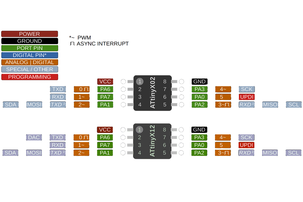
Page 13 displayed the pinouts for my microcontroller which I used later on to program my board.
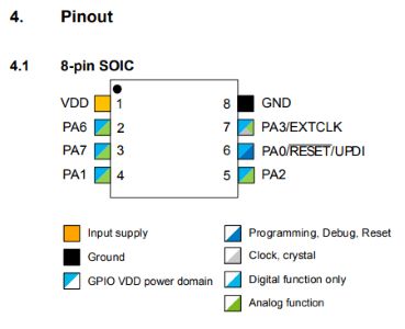
While I already knew the pinouts of my board from other sources, what’s different about the datasheet is that instead of just saying pin numbers and sequences of letters it had a key below the diagram that gave me much more information on the capabilities of each pin.
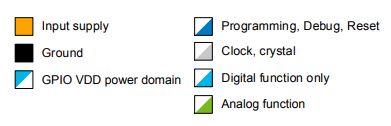
What it showed me was that while most of the pins had digital some of them also had analog meaning I could get more detailed inputs from sensors and such. It also showed me which pin had the clock, that being PA3 or Pin 7, which was also useful.
Page 105¶
Page 105 was very useful for many reasons. It helped me understand electronically how the pins actually functioned.
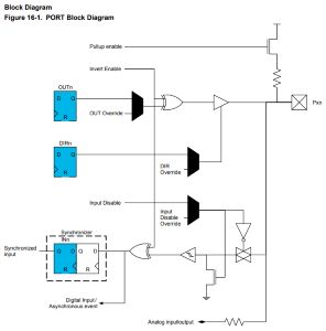
What is also very significant about this diagram is that it showed it had no pulldown resistor. This is super important as this was the reason my first PCB failed to function during Week 6, leading me down a rabbit hole of having to completely redesign mill and solder three more boards. What this proved to me is why the datasheet is so useful, had I read this prior to working with ATTinys I wouldn’t have encountered that error.
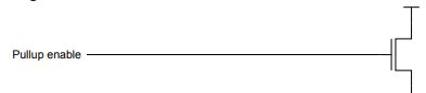
Image of the pullup resistor, while in the previous diagram no pulldown was shown.
The other important thing is that the datasheet explains all of uses for the pins further down.
Conclusion¶
I did look further into the sheet past what I documented here, but I learned how important reading and investigating the datasheet for your microcontroller truly is. It gives you super important insight into what you are working with and can help prevent countless electronic and software-based mistakes from simply doing a little looking around. I will definitly will be looking into datasheets for all the microcontrollers I use in the future.
Assignment #2: Use your Programmer to Program your Board to do Something¶
Previous Work¶
When it comes to making a custom board and programming it to do something using my programmer, I would like to direct you to here where I already completed this task in a previous week at the same time as completing that week. I went through the process of designing a PCB in KiCad with this future week in mind so that I could use it for this week as well. It is an ATTiny412 board that has a button and LED, and the button is an input in the arduino code which uses the LED output to turn it on and off. Below I have also relinked the video of that completed board here:
I used the following code on that board to get those results:
void setup() {
  Serial.begin(9600);
  pinMode(2, INPUT_PULLUP);
  pinMode(1, OUTPUT);
}

void loop() {
  int sensorVal = digitalRead(2);
  Serial.println(sensorVal);
  if (sensorVal == HIGH) {
    digitalWrite(1, LOW);
  } else {
    digitalWrite(1, HIGH);
  }
}
Further Investigation¶
Since this task was already completed, I knew I could do much more work with the board and get a deeper understanding of the chip and electronics. I then looked into using binary in the Arduino IDE to directly acsess the memory of the chip. This would help me understand how the chip works a lot better.
The following documentation is extra work we did in our lab specifically, so this documentation may not yet be complete since it is not technically required.
Baremetal Programming¶
We also learned to use binary and decimal to directly accsess the pinout addresses of a chip starting with an Arduino.
To start after watching a presentation found here by our instructor I worked in TinkerCircuit. I designed a basic circuit to flash an LED.
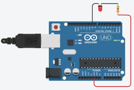
I programmed to flash the light first in Binary:
void setup()
{
  pinMode(9, OUTPUT);
}

void loop()
{
  PORTB=B00000010;
  delay(1000);
  PORTB=B00000000;
  delay(1000);
}
And then using decimal:
void setup()
{
  pinMode(9, OUTPUT);
}

void loop()
{
  PORTB=2;
  delay(1000);
  PORTB=0;
  delay(1000);
}
Then I used a third method:
void setup()
{
  //pinMode(9, OUTPUT);
  DDRB = 9;
}

void loop()
{
  PORTB=2;
  delay(1000);
  PORTB=0;
  delay(1000);
}
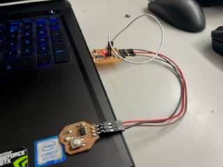
After this I went to use my Week 6 board which already had this week’s work done ahead of time and this time I used Baremetal Programming to program the LED on the PCB to blink.
I got out my programmer and old board and hooked them to my computer.
Keep in mind I used Pin 9 for my LED in this code.
I began writing my code for the board. I reviewed the KiCad schematic and my previous documentation to know that the LED was in Arduino port 1. Using the page 13 datasheet documentation found in this week’s documentation here and the chart in that:
And matching it with my KiCad schematic:
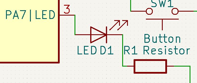
Who’s LED output was PA7 and on the chart it corelates to the RXD/Pin 1 in Arduino. I used the chart linked on my documention here at this link for the chart.
I then wrote my code which would blink the light but using the binary and memory. I wasn’t sure exactly how to go about the syntax, so I looked at fellow Fab student Alaric Pan’s website. This guided me to page 108 of the ATTiny412 datasheet which I mentioned earlier.
My board’s light was considered PA7. This falls under the ATTiny’s port category A, or in syntax PORTA. I looked over and spoke with Alaric and this was his code:
void setup() {
  // put your setup code here, to run once:
  PORTA.DIRSET |= 1 << 7;
}

void loop() {
  // put your main code here, to run repeatedly:
  PORTA.OUT |= 1 << 7; //sets to high
  delay(100);
  PORTA.OUT &= ~(1 << 7); //sets to low
  delay(100);
}
Looking over Alaric’s previously linked code, and also speaking with him, I learned what the 1 << 7 syntax means. The 7 in that is the distance the 1 bit is shifted in the byte of memory in which the pinout status’s are saved too. Essentially, it is setting the 7th pin to 1, or HIGH, but not effecting any other bit in the byte. Since in binary a byte is 8 bits, and I was using PA7 or Pin 7, and binary reads right to left, I needed to shift the 1 in 1 << 7 7 bits to the left for it to turn PA7 to HIGH, accompanied by the operator |= for setting a bit to 1 and &= ~() to set a bit to LOW. We both used the same pin number for our LED, PA7, so I didn’t have to alter the code much.
int pinNum = 7; //Number for LED Pin
int delayTime = 1000; //Delay time between blinks

void setup() {
  PORTA.DIRSET |= 1 << pinNum;
}

void loop() {
  PORTA.OUT |= 1 << pinNum;
  delay(delayTime);
  PORTA.OUT &= ~(1 << pinNum);
  delay(delayTime);
}
This resulted in a sucsess, I had now coded my blink board to blink using binary.
Dowloads¶
All of the code can be copied here:
int pinNum = 7; //Number for LED Pin
int delayTime = 1000; //Delay time between blinks

void setup() {
  PORTA.DIRSET |= 1 << pinNum;
}

void loop() {
  PORTA.OUT |= 1 << pinNum;
  delay(delayTime);
  PORTA.OUT &= ~(1 << pinNum);
  delay(delayTime);
}
§ Assignment 2: Group Work (Compare the Performance and Development Workflows for Other Architectures) §¶
All group work is documented on your group site, found here.
For this week, I did all of our group’s raspberry pi work including the Arduino research and comparison. I documented all of it and also wrote code and built a circuit to blink an LED on the Pi.
Week Summary¶
Overall this week was very important especially towards working on my final project. This week taught me the basics of input and output and gave me a MUCH MUCH deeper understanding of chips and programming. I know I will be coming back to this week’s documentation as a result.