Week 10: Output Devices
This week I designed a board that incorpoerated all of my final project’s outputs, learned TONS about current, voltage, and resistance, as well as furtherd my skill in board design and coding.
Assignment #1: Add an Output Device to a Microcontroller Board You’ve Designed, and Program it to do Something
Goals
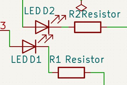
My goal for this week was to design an output from my final project and use a custom board to make it work. For my final project, it required a water pump to pump the water to the gardens. I began by opening the schematic from that project to prepare to add the pump output from the chip. I first added a second LED plugged into the prior button input pin. The purpose of this was to enable it whenever the board was attempting to pump water, that way I could debug it better if I had any issues.
Before I added the pump I needed to do some research on the pump and how to power and toggle it do to the high wattage.
Research
I knew my final project needed 2 LEDs and a pump in terms of output. I looked into the power consumption of my system.
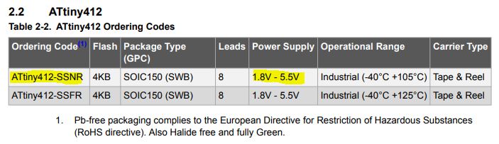
First, I used page 11 of the ATTiny Datasheet to get that the chip required around 5v. My pump needed 12v, and each LED needed around 3v, but as long as those lights were getting power from the chip they were irrelevent.
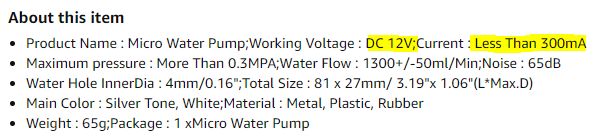
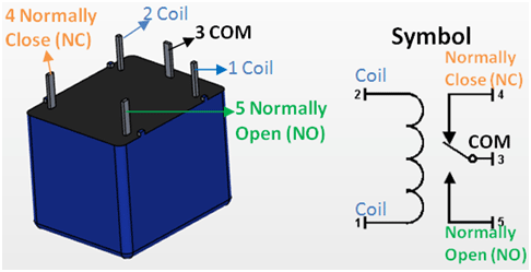
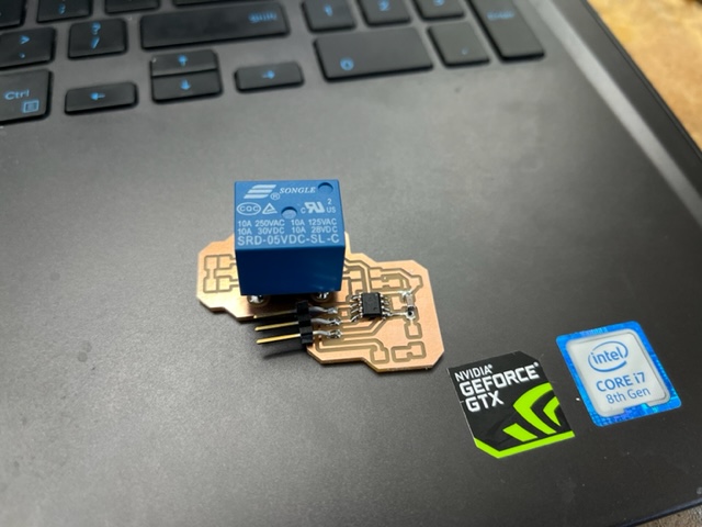
I knew that for this board, I was simply going to have a seperate 12v power supply to power the pump, but I needed a way to toggle the pump as it simply had VCC and ground. According to my instructor, I should look into relays. I began my research on how relays could assist me in toggling the pump without exposing the chip to the high current and voltage of the pump.
Using this site, I learned that for my case I could use a normally closed Relay, as in the power woudln’t flow through the relay until a seperate output triggered it, that ouput could simply be configured from my chip. This made tons of sense and I could easily see how Relays could be super useful. I went to see if our lab already had relays that could withstand the voltage/current.
After searching we did not have any. I furthered my online research for the time being. I found an excelent explanation on how relays work here and it also included code example which would come in handy. After this I searched for a relay which would work.
Ultimately, I found that this relay should work with the voltage and amperage I was planning to use. It could withstand the 12v dc current as well as up to 10 amps.
Lastly, I looked for a 12v supply in our lab I could use. I found one pretty easily, it had a value of 12v and 5A output, so I needed to do research on how to lessen amperage. I decided to mess around in tinkercad’s circuit builder to figure it out.
Note from future me: I end up finding a DC relay in our lab, just a heads up.
What I found was adding resistance would lower my amperage whilst mantaining my voltage. I used a power supply and set it to the exact same voltage and current was what I was going to use and found the exact ohm resistance I would need, doing so by creating this circuit:
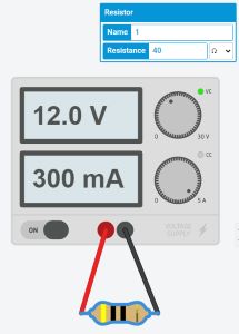
This project can be found here
This meant I would need a 40 ohm resistor coming off of my supply into my relay to my pump. I hopped onto notability to draw out the overall schematic for my new board and its external components.
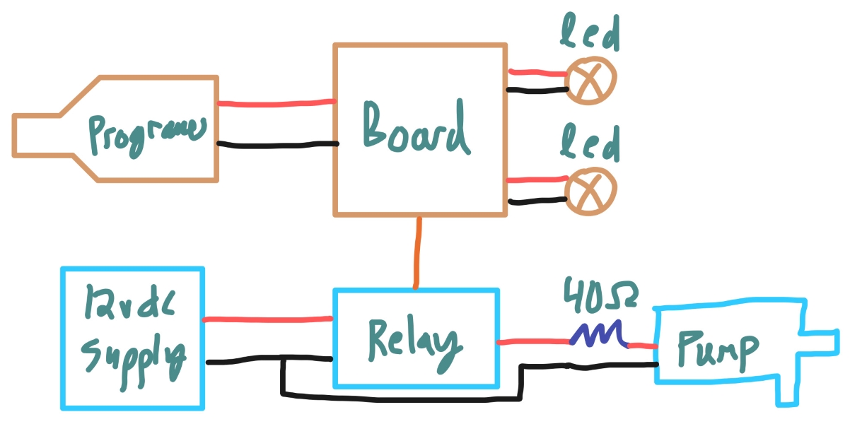
Note that the image above is primarily for the pump design so additional parts such as resistors on the LEDs were intentionally not written in.
And finally I went to right the code for my new board before I began milling/designing the new board.
Coding the New Board
To begin I brought in my last board’s code so that I could modify over top of it:
void setup() {
  Serial.begin(9600);
  pinMode(2, INPUT_PULLUP);
  pinMode(1, OUTPUT);
}

void loop() {
  int sensorVal = digitalRead(2);
  Serial.println(sensorVal);
  if (sensorVal == HIGH) {
    digitalWrite(1, LOW);
  } else {
    digitalWrite(1, HIGH);
  }
}
I wanted to start by:
- Renaming variables
- Adding new required variables
- Adding funcions/logic needed for what I was going to do, incorporating the research-found code on the use of relays
And I did so, getting this as my final code in around 5 minutes:
const int ledBoardOn = 1;
const int ledPumpOn = 2;

const int pumpRelayActivation = 4;

void setup() {
  Serial.begin(9600);
  pinMode(ledBoardOn, OUTPUT);
  pinMode(ledPumpOn, OUTPUT);

  digitalWrite(ledBoardOn, HIGH);
  pump(false);
}

void loop() {
  delay(30000); //Wait 30 Seconds
  pump(true); //Pump for 30 Seconds
  delay(30000); //Wait Another 30 Seconds
  pump(false); //Turn the Pump Off for Another 30 Seconds
}

void pump(bool on){
  if (on){
    //Enable Pump & Pumping Light
    digitalWrite(pumpRelayActivation, LOW); //Enables Pump Relay
    digitalWrite(ledPumpOn, HIGH); //Enable Pumping Light
  }
  else{
    //Disable Pump & Pumping Light
    digitalWrite(pumpRelayActivation, HIGH); //Disables Pump Relay
    digitalWrite(ledPumpOn, LOW); //Disable Pumping Light
  }
}
By this point I had to wait until my board was done and soldered to actual see if it worked or needed any edits.
Designing the New Board
I began by downloading and creating a new project with my week 6 downloads/board that I had made as I was going to modify it for my output, the downloads from that week can be found here.
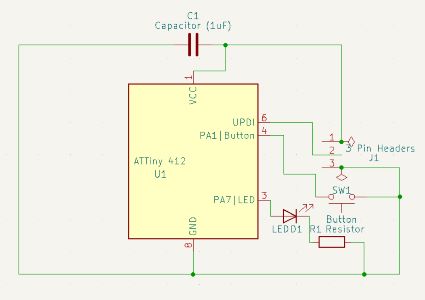
The above image is the base schematic from week 6 that I will be modifying
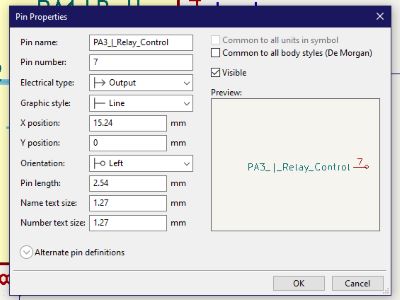
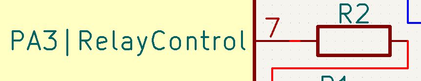
For my board, after adding the LED, all I had to do was add a single pin header from the correct chip in which would lead a jumper to the relay eventually, so I did so in the schematic view of KiCad, first by editing the symbol for my ATTiny412 to add the PA3 pin, which would act as my relay toggle as Arduino pin 4.
I also renamed old pin names that would be changed on this new board such as the old “Button” pin. I then actually added the 1x1 header to the schematic:
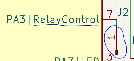
This is what my schematic looked like when I was done:
I then headed over to the PCB trace drawing menu to draw my additionally needed traces. I ended up just redrawing the entire board since so many things were changed. I ended up with this:
I also of course ran the electronic rules check in KiCad first before swithcing over, make sure you do this to insure no annoying mistakes which you would have to later put up with.
And then I added the edge cuts and was ready to export assuming everything was electronically correct.
I end up doing tons more research and making big changes and completly redoing my KiCad work, just a heads up.
Testing the Pump
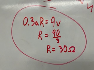
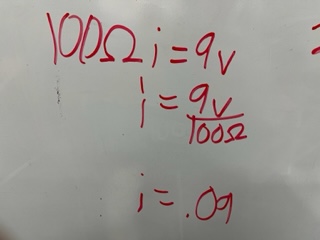
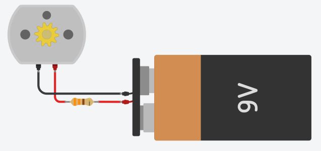
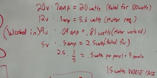
Once my pump arrived, I wanted to test it out. Using Ohm’s Law, I calculated that I would need a 30 ohm resistor on a 9v battery to safely power my pump. I went through our lab’s storage but only found 100 ohms to be the smallest, and from a second calculation seen in the second image below, it would still give me enough amperage to see if the pump worked.
I then tested it in tinker circuit with sucsess:
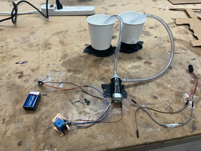
I then stripped and cut wire, cut tubing, grabbed my resistor, and put it all together.

And then I tested it using two cups, one with water with SUCSESS!
My pump circuit used 100 ohms of resistance, reason being I calculated 30 ohms to be a safe resistance for my pump (it would be at the exact current and under the voltage max) but our lab only had 100 minimum, so that was my mindset behind choosing 100 ohms even though my calculations proved 30 to be best
Further edits to my Board Design
After speaking with my instructor, I relaized I wanted to go ahead and take the leap to using solar panels for my board this week as I would in my final project.
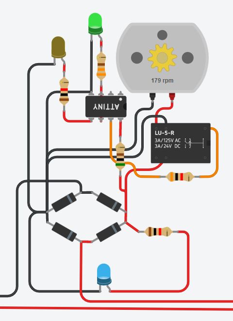
I went to design my circuit that I had begun in KiCad but in Tinker Circuit so I could build the entire idea out.
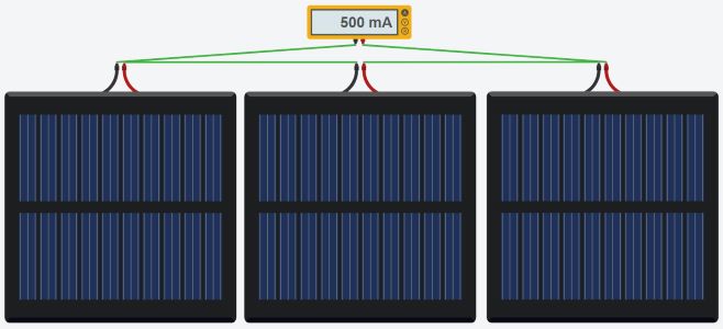
I looked for good solar panels I could use, and I found some here on amazon that were 5v 500mA. After experimenting with TinkerCicuit, I drew up a schematic on how to add up the current and voltages correctly.
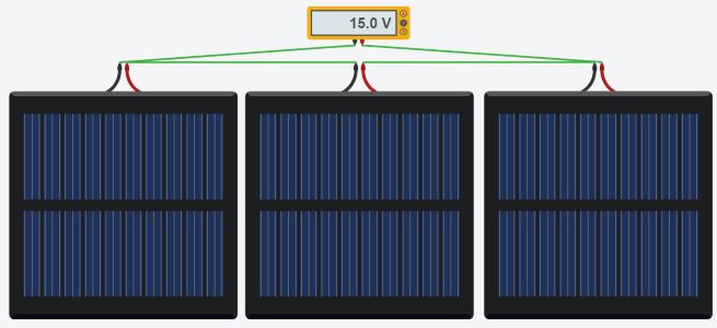
I designed what the final cicuit for my project would look like:
I used the multimeter tool to make sure each component got enought voltage and current, but not too much.
Then I added the relay and organized it:
I then added the code I created with a few small modifications so it would work with the tinker circuit IDE.
#define PB0 0
#define PB1 1
#define PB2 2

const int ledBoardOn = 1;
const int ledPumpOn = 0;

const int pumpRelayActivation = 2;

void setup() {
  pinMode(ledBoardOn, OUTPUT);
  pinMode(ledPumpOn, OUTPUT);

  digitalWrite(ledBoardOn, HIGH);
  pump(false);
}

void loop() {
  delay(5000); //Wait 30 Seconds
  pump(true); //Pump for 30 Seconds
  delay(5000); //Wait Another 30 Seconds
  pump(false); //Turn the Pump Off for Another 30 Seconds
}

void pump(bool on){
  if (on){
    //Enable Pump & Pumping Light
    digitalWrite(pumpRelayActivation, LOW); //Enables Pump Relay
    digitalWrite(ledPumpOn, LOW); //Enable Pumping Light
  }
  else{
    //Disable Pump & Pumping Light
    digitalWrite(pumpRelayActivation, HIGH); //Disables Pump Relay
    digitalWrite(ledPumpOn, HIGH); //Disable Pumping Light
  }
}
The link to my tinkercad project is here: Link
Testing Solar Panels
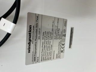
I worked tons on calculating wattage about panels and such and speaking with Dr. Adam Harris. From testing my pump in the prior week and running the calculations now, I knew I needed to wire 3 of the panels from here in series in order to get enough wattage even in unideal conditions. I determined this through my own experiments with our lab’s massive solar panels.
I found that in un-ideal conditions, the panel got 20 watts of power when the panel was rated for 100 watts max. I calculated through this (as seen below) I would assume to get 1/5 the rated power of my smaller panels to see if it would be enough, and according to my calculations 3 of my smaller panels in series should be enough wattage to power my tiny as well as the pump and sensors.
Remodeling my Tinker Circuit
After these calculations and this new info, I went back to entirely redesign my tinker circuit.
I wanted to first make sure my solar panels would produce enough, so I tracked the voltage and amperage consumption:
Using page 11 of the ATTiny 412 Datasheet I found it’s voltage consumption
| Name | Voltage Consumption | Amperage Consumption | Overall Power Usage |
|---|---|---|---|
| ATTiny 412 | 5.5v | .1 amp | .55 watts |
| Pump | 9v | .09 amp | .81 watts |
| Relay | 5v | .072 amp | .36 watts |
| Total: | 19.5v | .262 amp | 1.72 watts |
I learned that voltage is even over all paths and current splits over each series path and the amp requirments for the entire system should be the max series amp path * total series paths. My max voltage for my system is 5v, and my max amperage is .172 amps. with my light factor of safety being around 4 to 5, I knew I should use enough panels to produce 20v and 1.4 amps. I hopped into tinker circuit to design it.
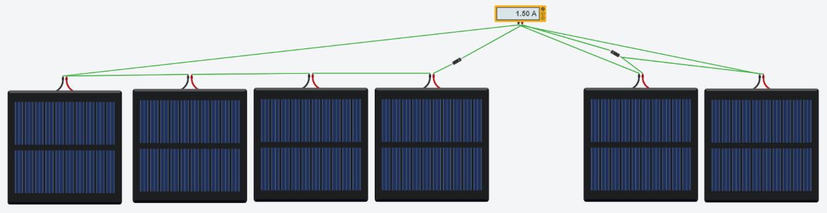
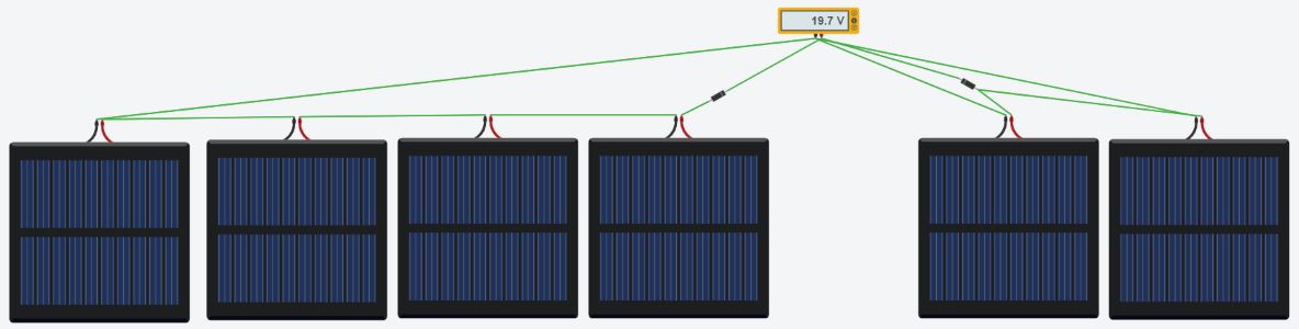
It looked like I needed 6 solar panels, some wired in paralell and some in series, 4 in series and 2 in paralell.
I redesigned my tinker circuit with this and my other edits in mind to get this:
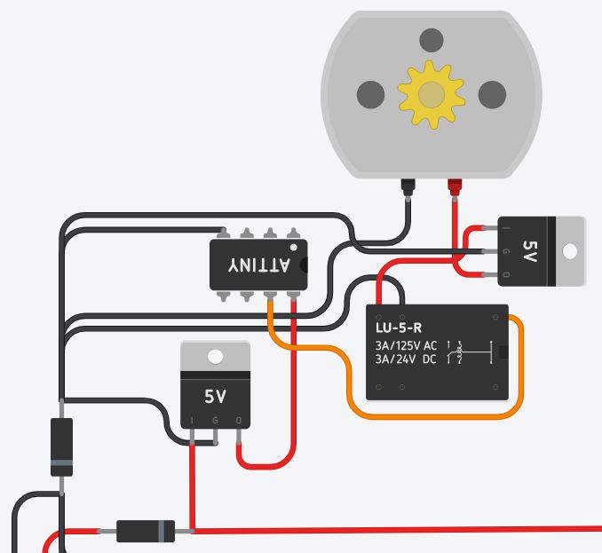
This also included the updated solar panel design. This design was much much much more power efficient then having the additional LEDs which I had in mind at the start, and this is much much safer in terms of the power it would require from the panels. In other words, this design is incredibly improved in comparison to my initial ideas/designs.
Finally Redesiging my Board
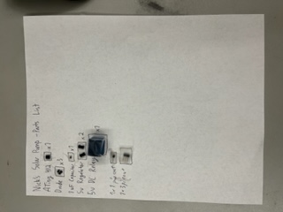
First I gathered the parts I’d need. Here is a list below:
| Name | Count |
|---|---|
| ATTiny 412 | 1x |
| 1 uF Capacitor | 1x |
| 5v Regulator | 2x |
| 5v DC Relay | 1x |
| 1x1 Pinout | 1x |
| 3x1 Pinout | 1x |
This parts list is innacurate and is updated later in the documnetation, if you are planning on buidling this, wait till later to get the realistic parts list.
Then I added all my parts into the schematic view and wired them according to my tinker circuit design found here.
I then remembered that the diodes would be needed on the solar array and not the board so I removed those.
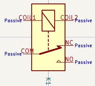
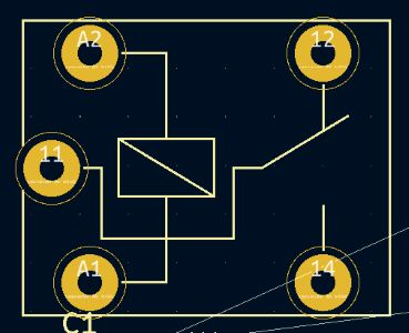
I reworked my tinker circuit design entirely because I realized a few issues with them. The new design is see above. I removed one of the regulators and correctly added the VCC to the relay. In KiCad, I remapped the symbol for the correct Relay so that the pinouts would be recognizable names as opposed to the strange numbers they have. I did so by bringing it into the PCB view and mapping it with the one I have:
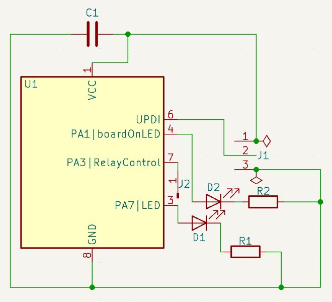
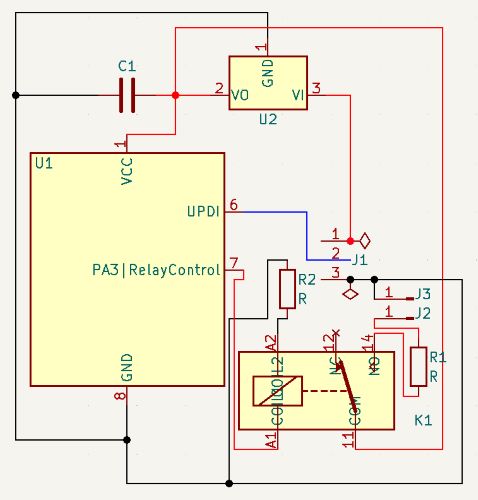
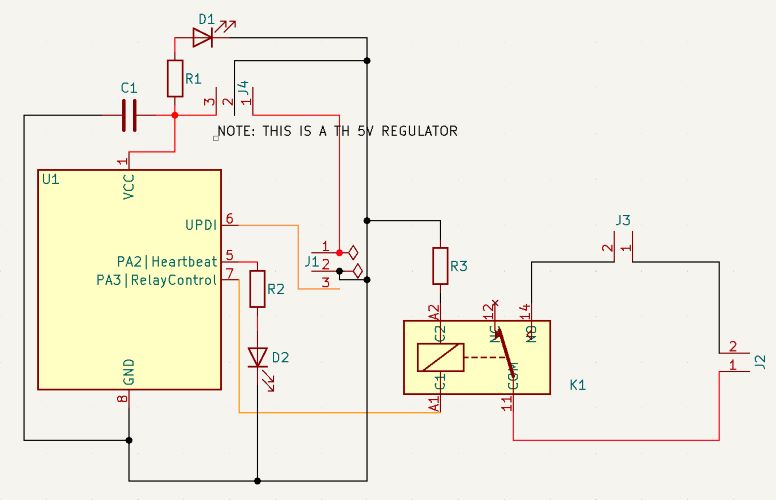
I finished redrawing my KiCad schematic in the schematic editor now, it looks like this:
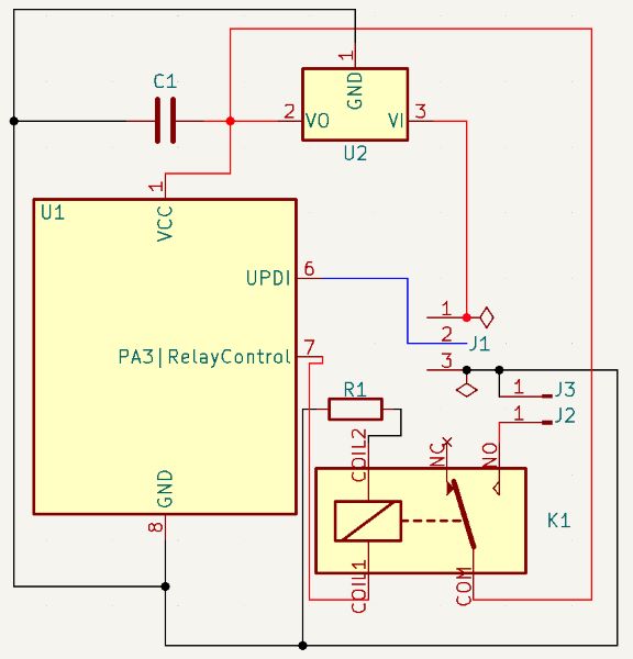
I added a second single pinout for the ground of my pump, that is the main difference. I also colored the wires in this one. Lastly I added a resistor to my relay trigger ground. Now it is time to jump into the PCB editor.
In the editor, I realized to make all the connections work I’d need to jump a zero ohm resistor over a trace, so I added that into my schematic and then my PCB.
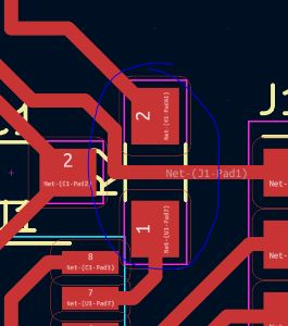
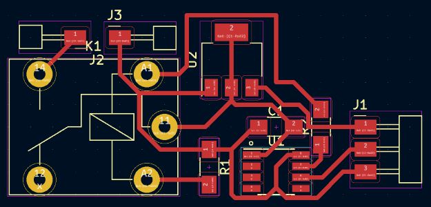
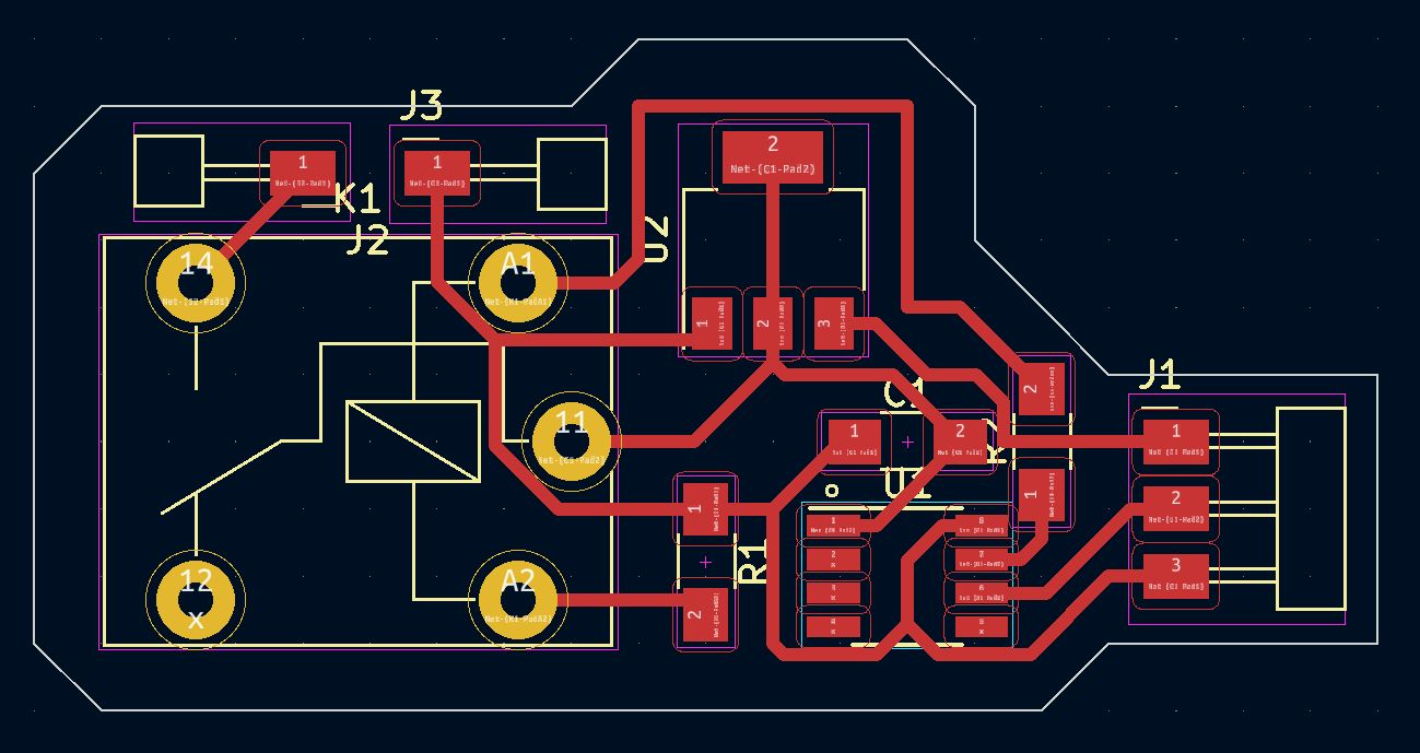
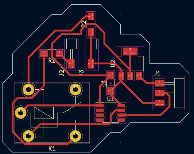
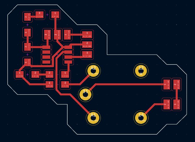
And ended up with this for my PCB design:
I then added the edge cuts:
And then went to do research about how KiCad handles through holes. Additionally, this is my new parts list:
| Name | Count |
|---|---|
| ATiny 412 | 1x |
| 1 uF Capacitor | 1x |
| 5v Regulator | 1x |
| 5v DC Relay | 1x |
| 1x1 Pinout | 2x |
| 3x1 Pinout | 1x |
| 0 Ohm Resistor | 1x |
| 330 Ohm Resistor | 1x |
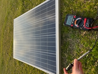
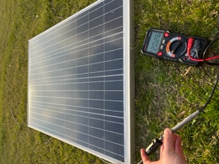
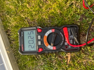
Further Testing the Big Panels
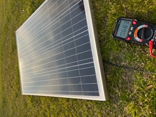
At around 4 PM in blue skies, I went into the field by our lab to test the panel’s output.
Layed flat, the panel produced 20v and 4.25 amps consistently. This comes out to around 85 watts compared to its 100 watt rating, meaning my panels would most certainly work. When angled towards the sun, it produced 20v and 6 amps, so around 120 watts compared to the 100 watt rating. This gave me more confidence.
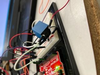
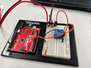
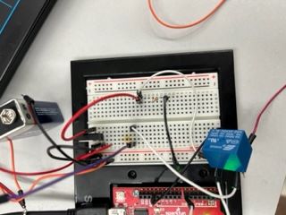
Building my KiCad Circuit on a Breadboard with an Ardunio
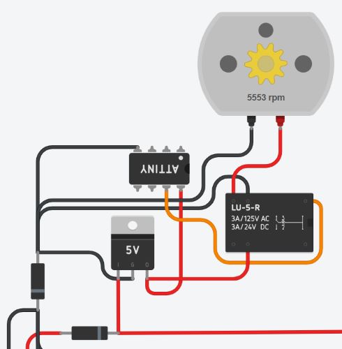
Before I milled my board, I wanted to test the entire circuit on a breadboard. I constructed it based on my KiCad schematic and an image found here. Using an Arduino and the constructed circuit as well as my code from above, I got my output to function perfectly:
Note that the pin for the relay activation in my previous code was changed to 7 for this to work!
This filled me with tons of confidence. I also wanted to draw up a KiCad schematic based off this meaning I’d make some edits to my prior schematic.
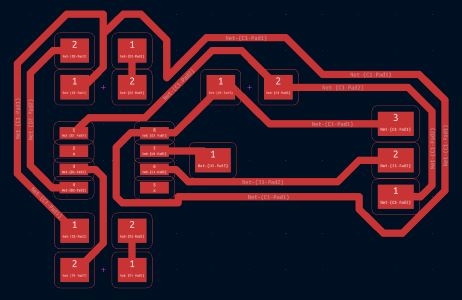
After trying to wire this in the PCB editor, I realized some of the 0 resistors I added to the above schematic overcomplicated things so I removed them and went to restart work on my PCB design. I did so and got this final board design:
My new parts list looked as follows:
| Name | Count |
|---|---|
| ATiny 412 | 1x |
| 1 uF Capacitor | 1x |
| 5v Regulator | 1x |
| 5v DC Relay | 1x |
| 1x1 Pinout | 2x |
| 3x1 Pinout | 1x |
| 330 Ohm Resistor | 1x |
| 100 Ohm Resistor | 1x |
I removed the 0 ohm resistor and added a new 100 ohm resistor compared to my previous list.
Additionally, I added extra annotations to my schematic file with values and part names.
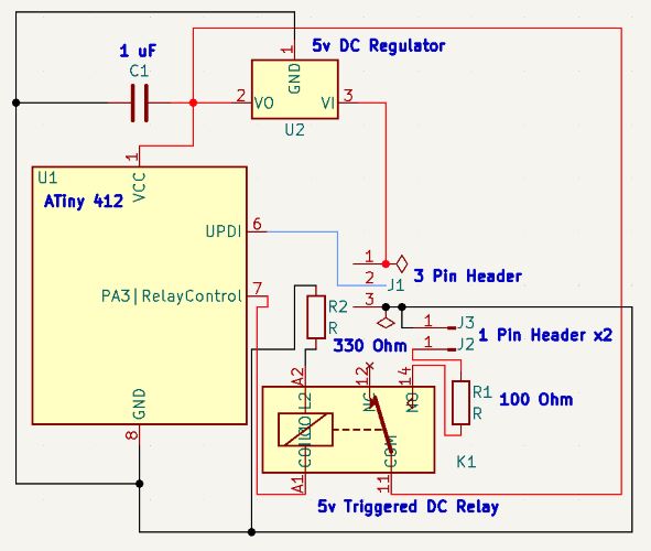
And I exported my gerber files to go and mill.
Milling and Soldering
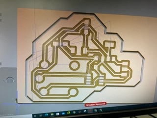
I followed the workflow to setup my file, however my drilled holes for my through hole relay were not appearing.
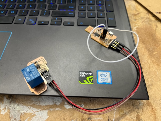
I realized additionally that the legs of the realy were too short and I remember becuase they didnt fit into jumper wires when I was doing my arduino build, so I decided it would be best to solder them atop the board instead of doing the through hole stuff. I finished soldering the remainder of the board and hooked it up to ny programmer to program it:
And the code sucsefully reached the ATTiny, but the relay wasn’t clicking and nothing was happening. After TONS of troubleshooting for an hour or so, I made some huge changes to my board which ended up fixing this issue. First, I had to bridge the vIn and vOut of the 5v regualtor together to void the regulator entirely. I then changed the 330 ohm resistor coming from Coil2 on the relay to ground to a 50 ohm resistor, and lastly changed the resistor going from the relay to the motor input to a 0 ohm resistor. Doing all of this, reprogramming it, then hooking it to only a 9v battery (Since my solar panels hadn’t arrived yet) on its own resulted in the relay finally clicking in a 5 seconds cycle.
I was super happy it finally worked, it felt incredible. Here was my code:
const int pumpRelayActivation = 4;

void setup() {
  pinMode(pumpRelayActivation, OUTPUT);
}

void loop() {
  delay(5000);
  digitalWrite(pumpRelayActivation, LOW);
  delay(5000);
  digitalWrite(pumpRelayActivation, HIGH);
}
All that was different in this code is I removed the pump function and changed the pin of pumpRelayActivation to pin 4.
Lastly, I added an LED to the relay output to further show it functioning but visually. Added just an LED to the relay pinout worked perfectly.
And finally I tried doing so with the pump, however this did not work for obvious reasons. The pump pulled way too much current and left the tiny and relay with nothing, but since I had my relay done for output work, I wasn’t too worried.
This was good, but not enough. Having a zero resistor and bridged regulator just simply to get my board to work was bad design, I needed to redesign my board and have it work properly.
Designing a New Board
For my new board, I wanted to make big changes. I wanted to essentially draw up two seperate circuits that would live on the same board. I wanted my pump in its own circuit and the ATTiny on another with the relay in the middle connecting the two in a sense. This would mean I would ultimately need two power supplies, which in this case I would assume to be 2 seperate 9v batteries. Eventually I would need two seperate solar panel circuits to power the circuits but for now I was focused on two 9vs.
Like I said, I needed to make changes:
- Remove the resistor that goes from the relay to the pump
- Alter the regulator
I figured out why the Regulator didn’t work: the SM one I was using supposadly only outputs 1.2v and low current, and my mistake was assuming the through hole component had the same output as the SM one, which is why the original 5v regulator worked with the arduino circuit but it didn’t when it was with the Tiny as surface mount.
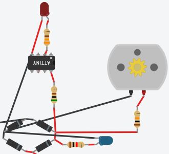
With this plan I jumped into designing based off a circuit I drew up in my notebook.
Above are my new designs. Note the three pin header coming off VCC of my chip’s circuit is actually a through hole 5 volt regulator, but since there is no component for that in KiCad, I am using a three pin header since they are the same sizes. Lastly, I wanted to calculate all the restance values the resistors would need for this to function.
Also note the addition of 2 LEDs to the circuit. One is an indicator that power is getting to the circuit for the chip, and the second is what I am calling a “heartbeat” LED. This is an output from my chip that through code will blink at a consistent pace, the point of this being to know if code is getting to and actually running through my chip. These two LEDs are merely for debugging and testing, essentially. I came up with the hearbeat idea since I noticed one of our lasercutters has a heartbeat light as well so I though I’d incorporate it here.
As mentioned, it was time to do calculations.
Further Changes
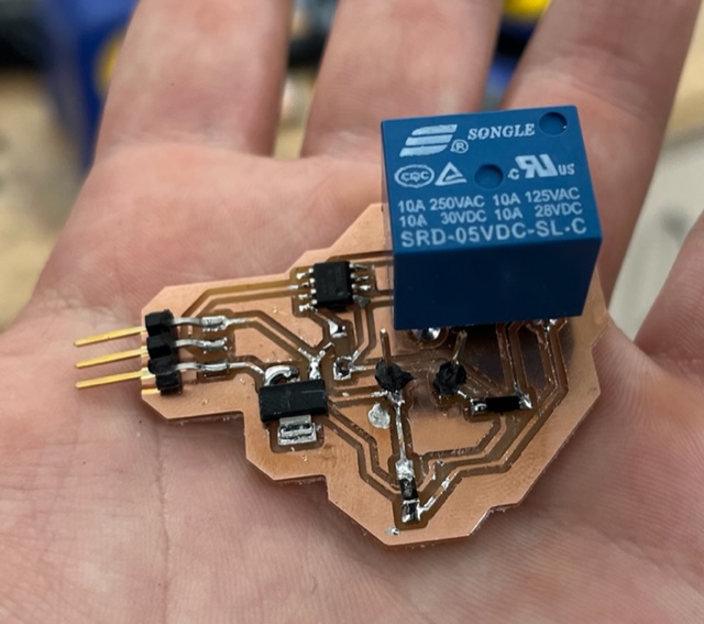
After another day went by, I had more inspiration. I decided to just use my programmer as the power supply for my tiny circuit in order to void the regulator as I was unsure about it. Knowing this, I removed the regulator and edited my PCB design with that. With this, I milled my PCB and soldered it.
I decided to hold off on adding the LEDs that way I could test my circuit. I plugged the soldered board into my programmer and computer.
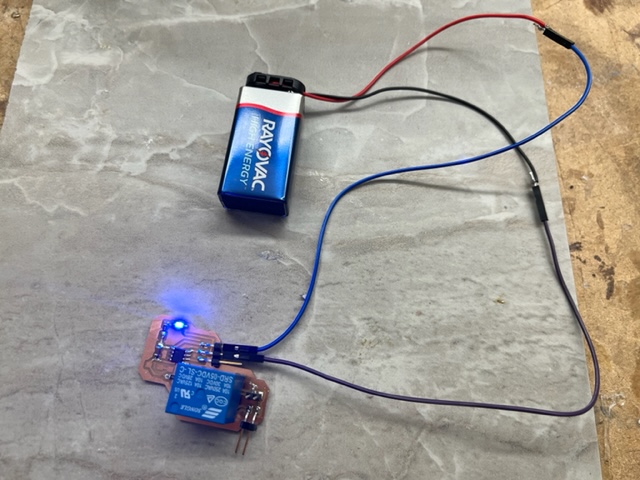
And I pushed the relay code. The code pushed sucsesfully, but the relay wasn’t clicking. I tested the relay coil output with a multimeter, and the high and low states were in fact toggling correctly every 5 seconds, but only with 1v, which was not near enough to trigger the relay. Knowing my previous circuit worked with a 9v, I risked my entire board and plugged it into a 9v battery, thinking surely it would blow the tiny, but to my amazed surprise, the tiny lived and the relay actually clicked on and off with a 9v battery!
I was astonished and confused at how the tiny could withstand the 9v, and so was my instructor. We could concluded that the relay must have some sort of resistance or something that was saving the tiny, but ultimately, I was happy it worked. This output board worked perfectly, and next I was going to attach the second power source and pump to see if it toggled the pump correctly.
Finally, Testing the Pump!
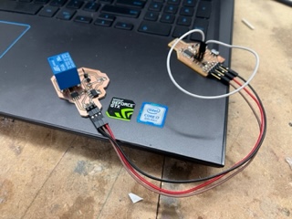
For the somewhat-finally I needed to plug in my pump. First I chopped two 9v to arduino plugs on the ardunio side, stripped the wires, and soldered jumper wires to them so that plugging 9v into my circuit would be easy to do. I then followed my schematic’s pinouts and correctly hooked it all together with sucsess.
I was super happy with the design and how everything worked out.
Lastly, and this time I promise, lastly, I wanted to add the power indicator LED and heartbeat LED and alter my code to acomidate that.
The Final Finale
I soldered on first my power indicator light and that worked out the gate with the 9v attached/programmer attached.
Then I soldered on my hearbeat LED and 330 ohm resistor. I then altered my code as the following to include the new LED:
const int pumpRelayActivation = 4;
const int hearbeatLight = 3;

int counter = 0;

void setup() {
  pinMode(pumpRelayActivation, OUTPUT);
  pinMode(hearbeatLight, OUTPUT);
}

void loop() {
  counter += 1;
  delay(125);

  // Hearbeat Toggle
  if (counter % 2 == 0){
    digitalWrite(hearbeatLight, HIGH);
  }
  else{
    digitalWrite(hearbeatLight, LOW);
  }

  // Relay Check
  if (counter % 40 == 0){
    digitalWrite(pumpRelayActivation, HIGH);
  }
  else if (counter % 70 == 0){
    digitalWrite(pumpRelayActivation, LOW);
  }

  // Counter Reset
  if (counter >= 71){
    counter = 0;
  }
}
Keep in mind I also added a counter system for the loop so that different components could be triggered at different times since Arduino goes line by line and can’t run functions in paralell (Meaning I couldn’t call a pump loop function and a heartbeat light function and have them blink in their own intervals otherwise). I consulted a lab instructer Mr. Durret who pointed me to use the mod operator in my code and an iterator to get this all to work. Doing so had my light sucsesfully blinking after a bit of troubleshooting with pushing the code:
Lastly, to finish it all off, I added the pump and second power source jumpers to get the whole thing working in its entirety with ALL of its features, and I couldn’t be happier with it:
Dowloads
Assignment 2: Group Work (Measure the Power Consumption of an Output Device)
All group work is documented on your group site, found here.
I contributed by using my pump. I set up two cups, one with water one without, and also attached clear tubing to my pump. I then took all the videos, uploaded and documented them, and lastly I adjusted the voltage at each increment it needed to be increased (Ran the power supply, essentially).
Week Summary
Overall, this was an incredibly educational and gratifying week for me. I learned TONS more about how electricity works as well as how current, voltage, and resistance relate to eachother. I learned how to calculate and apply Ohms law and on top of that went much into depth and learned how Relays as well as Motors actually function. Overall, an amazing week.