In-Depth Development & Documentation
This page is a log of changes/additions to my final project. They are categorized by the time period in which they were developed.
Weeks Prior Where I worked on this Project:
Weeks 1 (Initial Planning): Link Week 2 (Initial Model/Rendering of Idea): Link Week 10 (Output Devices): Link Week 12 (Input Devices): Link Week 14 (Initial Interfacing): Link Week 15 (Embroidery): Link
Pre-June
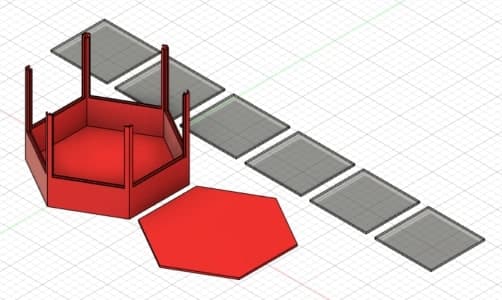
My final project is what I call a Modular Garden. The goal is to create an entirely self-sustaining and modular in size & shape garden that works entirely by itself. It uses and stores both solar energy and rain water. It is constructed through what are called “Units”, or hexagonal connecting pieces that serve different purposes and fit together tightly. There are only two distinct units, though they can be constructed in different ways for different purposes.
Initial 3D Modeling
Gardening
There is a gardening unit which houses the soil & plants, and which also protects the plants from any elements outside of the glass walls (Which can be slid off and removed).
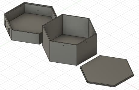
Master
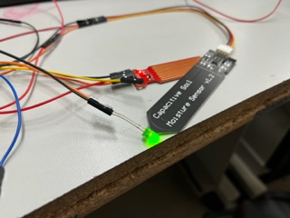
There is also a master unit which houses the electronics. This includes the pump with water tank on top, solar panels lining the sides, a battery charged via solar, as well as indicator lights and other electronics such as soil moisture sensors for the surounding units.
Prototype Demos
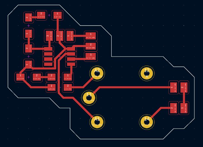
Outputs
If you’d like to read more about the construction or creation of any of the below demo, it can be found here from Week 10 (Output Week)
This is a showcase of this board below designed in KiCad then milled, soldered, and programmed:
The code for the final board (including inputs and outputs) is listed in the “Code” section.
Inputs
If you’d like to read more about the construction or creation of any of the below demo, it can be found here from Week 12 (Input Week)
The code for the final board (including inputs and outputs) is listed in the “Code” section.
Display/Interfacing
Code
The code below is all of the arduino which manages all of my inputs & outputs of my final project board as of now (subject to change).
const int waterLevelPin = 1;
const int soilMoisturePin = 2;
const int pumpRelayActivation = 4;
const int hearbeatLight = 3;

int counter = 0;
float currentSoilMoisture = 0;
float currentWaterLevel = 0;

void setup() {
  pinMode(pumpRelayActivation, OUTPUT);
  pinMode(hearbeatLight, OUTPUT);
}

void loop() {
  counter += 1;
  delay(125);

  // Hearbeat Toggle
  if (counter % 2 == 0){
    digitalWrite(hearbeatLight, HIGH);
  }
  else{
    digitalWrite(hearbeatLight, LOW);
  }

  // Relay Check
  if (counter % 40 == 0){
    digitalWrite(pumpRelayActivation, HIGH);
  }
  else if (counter % 70 == 0){
    digitalWrite(pumpRelayActivation, LOW);
  }

  //Soil Moisture Data Calculation
  for (int i = 0; i <= 100; i++)
  {
    currentSoilMoisture = currentSoilMoisture + analogRead(soilMoisturePin);
    delay(1);
  }

  currentSoilMoisture = currentSoilMoisture/100.0;

  if (currentSoilMoisture > 400){
    //Soil is moist
  }

  //Water Level Data
  int currentWaterLevel = analogRead(waterLevelPin);

  if (currentWaterLevel > 10){
    //Tank full
  }

  // Counter Reset
  if (counter >= 71){
    counter = 0;
  }
}
And this code reads the .txt in which serial data from my input is ported to and interprets it in Unity using C#:
using System.Collections;
using System.Collections.Generic;
using UnityEngine;
using TMPro;
using System;
using System.IO;
using System.Text;
using UnityEngine.UI;

public class SensorText : MonoBehaviour
{
    public TextMeshProUGUI sensorText;
    public const string filePath = "C:/Users/nicho/OneDrive/Desktop/CoolTerm Capture 2022-05-05 15-55-02";

    public Transform rainOrigin;
    public GameObject rainObject;

    private List<ParticleSystem> rains = new List<ParticleSystem>();

    public bool inDebug = true;
    public float mositure;

    public GameObject greenScene;
    public GameObject desertScene;

    public Image bar;

    void Start()
    {
        sensorText = this.gameObject.GetComponent<TextMeshProUGUI>();
    }

    void Update()
    {
        UpdateSensorText();
    }

    public void UpdateSensorText()
    {
        if (inDebug)
        {
            UpdateRain(mositure);
            return;
        }

        if (File.Exists(filePath + ".txt"))
        {
            float sensorVal = 0.0f;

            string sourceFile = filePath + ".txt";
            string destinationFile = filePath + "1.txt";
            try
            {
                File.Copy(sourceFile, destinationFile, true);
                string fileData = System.IO.File.ReadAllText(destinationFile);
                string[] data = fileData.Split('&');
                //print(float.Parse(data[data.Length - 1]));

                print(data[data.Length - 1]);
                try
                {
                    sensorVal = float.Parse(data[data.Length - 1]);
                }
                catch (FormatException iox)
                {
                    return;
                }
                print(data[data.Length - 1]);
                sensorVal = Mathf.Abs(100 - (((sensorVal - 316) / 359) * 100));
                sensorVal = ((Mathf.RoundToInt(sensorVal * 100)) / 100);

                if (sensorVal < 0)
                {
                    sensorVal = 0;
                }
                else if (sensorVal > 100)
                {
                    return;
                    sensorVal = 100;
                }

                UpdateRain(sensorVal);
                sensorText.text = "Soil Moisture: " + sensorVal.ToString() + "%";

                File.Delete(destinationFile);
            }
            catch (IOException iox)
            {

            }
        }
        else
        {
            Debug.Log("File not found...");
        }
    }

    public void UpdateRain(float reading)
    {
        if (reading > 100)
        {
            reading = 100;
        }
        else if (reading < 0)
        {
            reading = 0;
        }

        bar.fillAmount = reading / 100;
        sensorText.text = "Soil Moisture: " + reading.ToString() + "%";

        if (reading <= 20)
        {
            //Have 0 rains

            desertScene.SetActive(true);
            greenScene.SetActive(false);

            if (rains.Count > 0)
            {
                List<ParticleSystem> toDestroy = new List<ParticleSystem>();

                foreach (ParticleSystem rain in rains)
                {
                    toDestroy.Add(rain);
                }

                for (int i = 0; i < toDestroy.Count; i++)
                {
                    toDestroy[i].Stop();
                    rains.Remove(toDestroy[i]);
                }
            }
        }
        else if (reading <= 40 && reading > 20)
        {
            //Have 1 rain

            desertScene.SetActive(false);
            greenScene.SetActive(true);

            List<ParticleSystem> toDestroy = new List<ParticleSystem>();

            foreach (ParticleSystem rain in rains)
            {
                if (rain != rains[0])
                {
                    toDestroy.Add(rain);
                }
            }

            for (int i = 0; i < toDestroy.Count; i++)
            {
                toDestroy[i].Stop();
                rains.Remove(toDestroy[i]);
            }

            if (rains.Count == 0)
            {
                rains.Add(Instantiate(rainObject, rainOrigin.transform.position, rainOrigin.transform.rotation, rainOrigin.transform).GetComponent<ParticleSystem>());
            }
        }
        else if (reading <= 60 && reading > 40)
        {
            //Have 2 rains

            desertScene.SetActive(false);
            greenScene.SetActive(true);

            List<ParticleSystem> toDestroy = new List<ParticleSystem>();

            foreach (ParticleSystem rain in rains)
            {
                if (rain != rains[0] && rain != rains[1])
                {
                    toDestroy.Add(rain);
                }
            }

            for (int i = 0; i < toDestroy.Count; i++)
            {
                toDestroy[i].Stop();
                rains.Remove(toDestroy[i]);
            }

            if (rains.Count == 0)
            {
                rains.Add(Instantiate(rainObject, rainOrigin.transform.position, rainOrigin.transform.rotation, rainOrigin.transform).GetComponent<ParticleSystem>());
                rains.Add(Instantiate(rainObject, rainOrigin.transform.position, rainOrigin.transform.rotation, rainOrigin.transform).GetComponent<ParticleSystem>());
            }
            else if (rains.Count == 1)
            {
                rains.Add(Instantiate(rainObject, rainOrigin.transform.position, rainOrigin.transform.rotation, rainOrigin.transform).GetComponent<ParticleSystem>());
            }
        }
        else if (reading <= 80 && reading > 60)
        {
            //Have 3 rains

            desertScene.SetActive(false);
            greenScene.SetActive(true);

            List<ParticleSystem> toDestroy = new List<ParticleSystem>();

            foreach (ParticleSystem rain in rains)
            {
                if (rain != rains[0] && rain != rains[1] && rain != rains[2])
                {
                    toDestroy.Add(rain);
                }
            }

            for (int i = 0; i < toDestroy.Count; i++)
            {
                toDestroy[i].Stop();
                rains.Remove(toDestroy[i]);
            }

            if (rains.Count == 0)
            {
                rains.Add(Instantiate(rainObject, rainOrigin.transform.position, rainOrigin.transform.rotation, rainOrigin.transform).GetComponent<ParticleSystem>());
                rains.Add(Instantiate(rainObject, rainOrigin.transform.position, rainOrigin.transform.rotation, rainOrigin.transform).GetComponent<ParticleSystem>());
                rains.Add(Instantiate(rainObject, rainOrigin.transform.position, rainOrigin.transform.rotation, rainOrigin.transform).GetComponent<ParticleSystem>());
            }
            else if (rains.Count == 1)
            {
                rains.Add(Instantiate(rainObject, rainOrigin.transform.position, rainOrigin.transform.rotation, rainOrigin.transform).GetComponent<ParticleSystem>());
                rains.Add(Instantiate(rainObject, rainOrigin.transform.position, rainOrigin.transform.rotation, rainOrigin.transform).GetComponent<ParticleSystem>());
            }
            else if (rains.Count == 2)
            {
                rains.Add(Instantiate(rainObject, rainOrigin.transform.position, rainOrigin.transform.rotation, rainOrigin.transform).GetComponent<ParticleSystem>());
            }
        }
        else if (reading <= 100 && reading > 80)
        {
            //Have 4 rains

            desertScene.SetActive(false);
            greenScene.SetActive(true);

            List<ParticleSystem> toDestroy = new List<ParticleSystem>();

            foreach (ParticleSystem rain in rains)
            {
                if (rain != rains[0] && rain != rains[1] && rain != rains[2] && rain != rains[3])
                {
                    toDestroy.Add(rain);
                }
            }

            for (int i = 0; i < toDestroy.Count; i++)
            {
                toDestroy[i].Stop();
                rains.Remove(toDestroy[i]);
            }

            if (rains.Count == 0)
            {
                rains.Add(Instantiate(rainObject, rainOrigin.transform.position, rainOrigin.transform.rotation, rainOrigin.transform).GetComponent<ParticleSystem>());
                rains.Add(Instantiate(rainObject, rainOrigin.transform.position, rainOrigin.transform.rotation, rainOrigin.transform).GetComponent<ParticleSystem>());
                rains.Add(Instantiate(rainObject, rainOrigin.transform.position, rainOrigin.transform.rotation, rainOrigin.transform).GetComponent<ParticleSystem>());
                rains.Add(Instantiate(rainObject, rainOrigin.transform.position, rainOrigin.transform.rotation, rainOrigin.transform).GetComponent<ParticleSystem>());
            }
            else if (rains.Count == 1)
            {
                rains.Add(Instantiate(rainObject, rainOrigin.transform.position, rainOrigin.transform.rotation, rainOrigin.transform).GetComponent<ParticleSystem>());
                rains.Add(Instantiate(rainObject, rainOrigin.transform.position, rainOrigin.transform.rotation, rainOrigin.transform).GetComponent<ParticleSystem>());
                rains.Add(Instantiate(rainObject, rainOrigin.transform.position, rainOrigin.transform.rotation, rainOrigin.transform).GetComponent<ParticleSystem>());
            }
            else if (rains.Count == 2)
            {
                rains.Add(Instantiate(rainObject, rainOrigin.transform.position, rainOrigin.transform.rotation, rainOrigin.transform).GetComponent<ParticleSystem>());
                rains.Add(Instantiate(rainObject, rainOrigin.transform.position, rainOrigin.transform.rotation, rainOrigin.transform).GetComponent<ParticleSystem>());
            }
            else if (rains.Count == 3)
            {
                rains.Add(Instantiate(rainObject, rainOrigin.transform.position, rainOrigin.transform.rotation, rainOrigin.transform).GetComponent<ParticleSystem>());
            }
        }
    }

}
HUGE Change of Direction in my Final Project
While working on interfacing week, I realized that I wanted to take my project in a new direction as to cut parts of the previous version which I found difficult but irrelevant but also to add to a newer version that would create much more depth to my project. Here is what I wanted to get rid of:
Solar power based Rain water collecting
Here is what I wanted to do:
Heavily develop a unity program to display sensor information, store it, and graph it Add a touchscreen built in to the master unit to display the information from the program
Why do I want to make these changes?
I want to refocus my project from a self-sustaining/running garden into a still self-sustaining garden but focused on plant research and information rather than simply growing plants.
Things needed to do to make these implementations:
Separate inputs and outputs into separate boards Be able to read serial information from the input board in python through the raspberry pi Build a unity program targeted for Linux and be able to run said program on the same pi reading the serial information Completely redesign the garden shells to incorporate all of the electronics and new screen
These four changes would put me on the right path to altering my project to this new research focused project.
This would also benefit me as it would further include more skills/weeks:
Week 14: Interface & Application Programming
- Touchscreen displaying Unity program
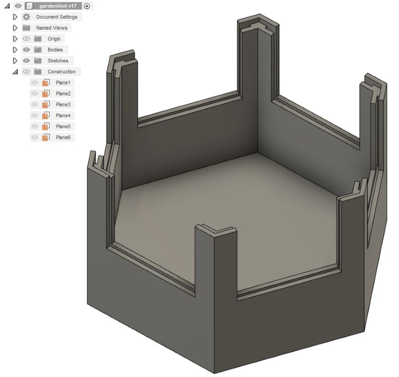
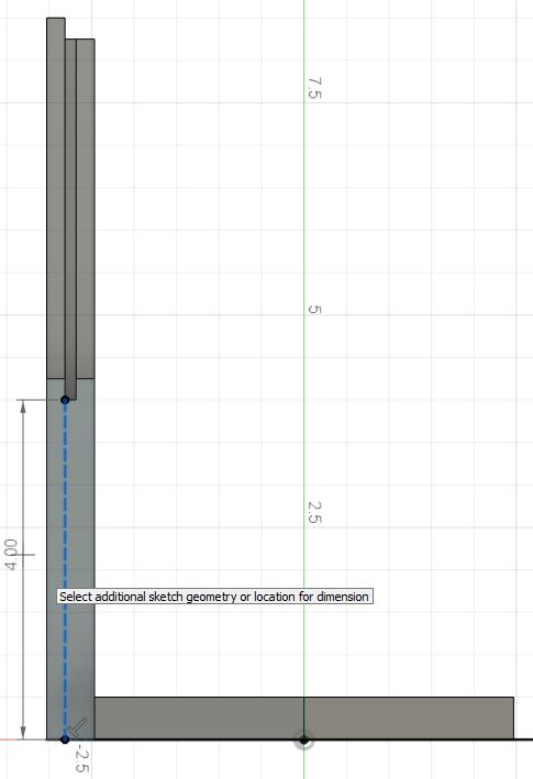
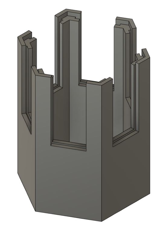
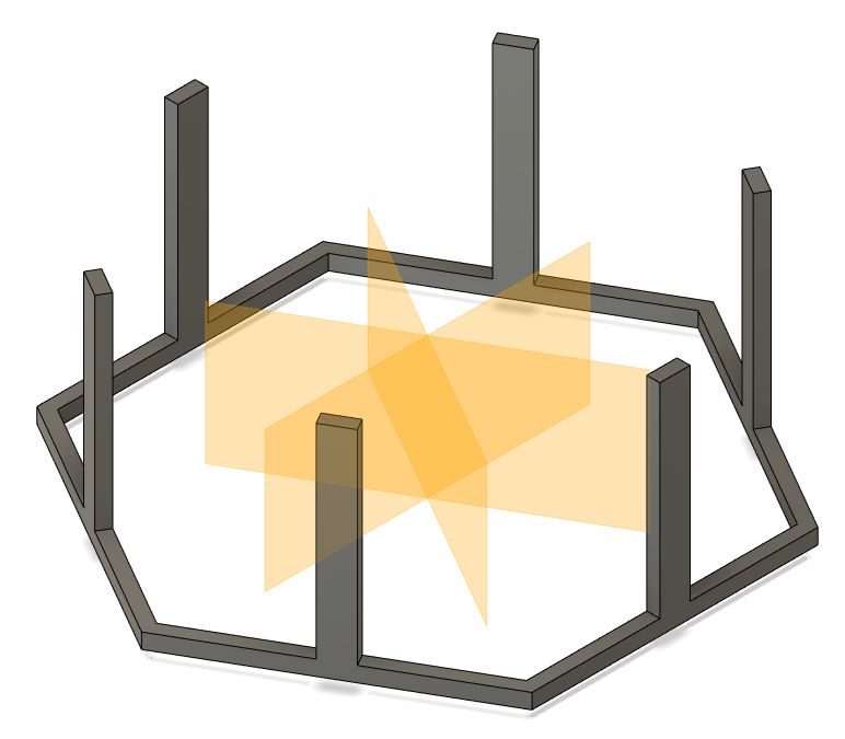
Entirely Redoing my 3D Models
Now that I changed the direction of my final project, I wanted to redo my 3D models entirely. My goal was to have all the unit shells to be entirely 3D printable. I measured the lab printer beds to be 7.5 inches by 7.5 inches. I decided to make my parts be 7 x 7 inches.
And I layered the outside so that the walling and such would be similar and allow an acrylic window to fit.
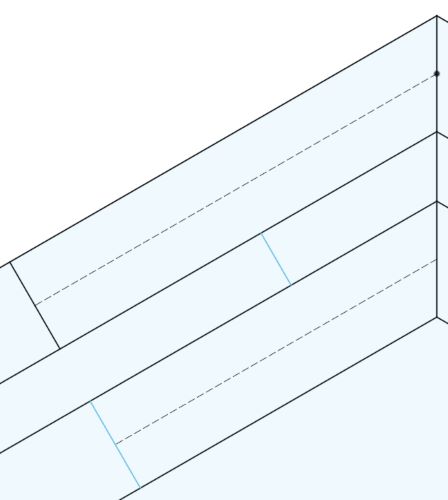
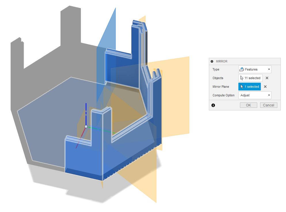
I then extruded these parts up with the correct dimensions, and began mirroring this shape all the way around the object using the offset plane and mirror tool.

This was the final product:
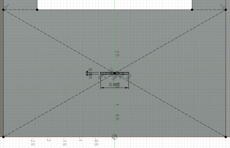
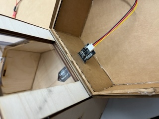
I then added a small slit for the soil moisture sensor:
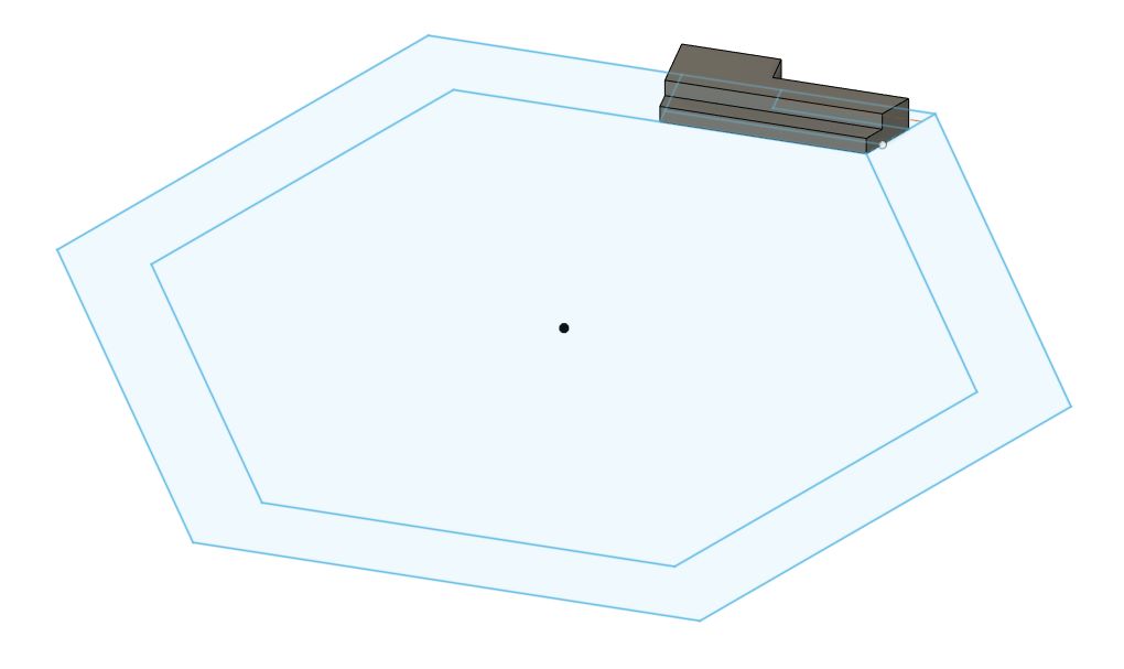
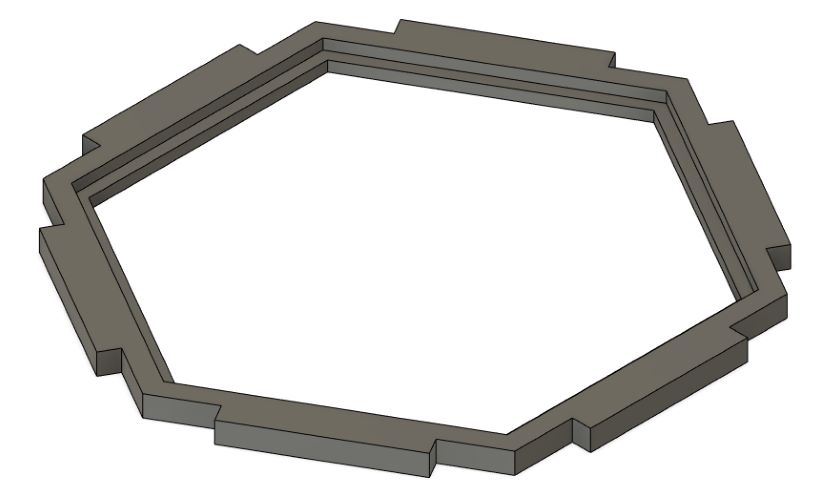
And now began working on the top. I drew up the base sketch:
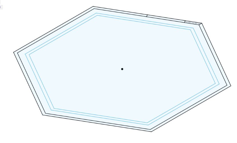
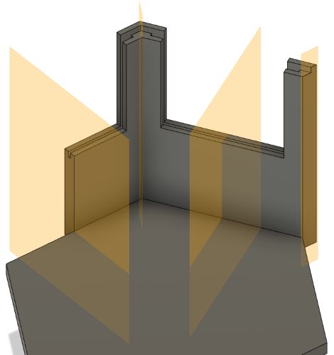
And from here extruded and mirrored accordingly to get this:
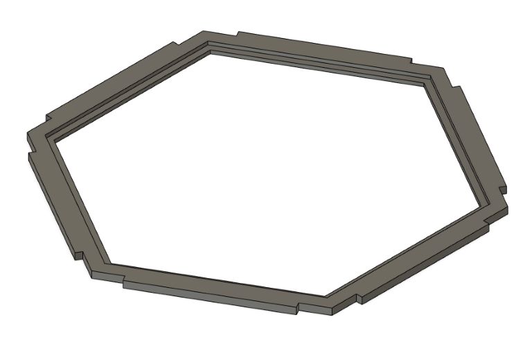
This allowed for an acrylic window to be placed atop so you can look in. Also note that the missing walling allows for removable acrylic windowing as well.
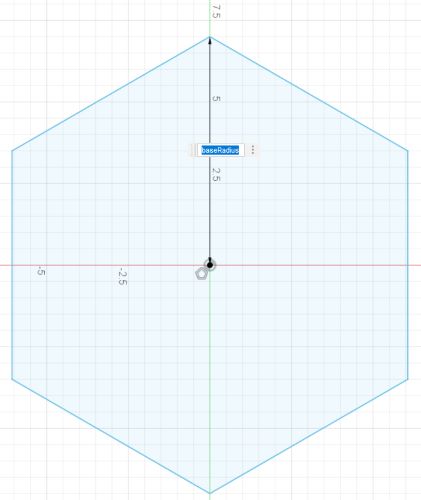
Redoing the Main Unit
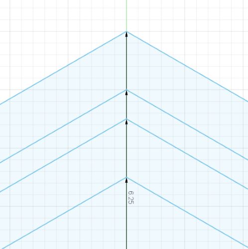
I then went to redesign my master unit. I first sketched a base hexagon with a radius of 7 inches. I then added an inner hexagon with a size of 6.75 inches. I then designed an encasing piece for my Pi:
I also extruded the hexagons accordingly:
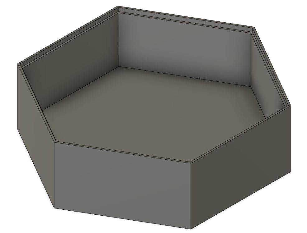
Design Error
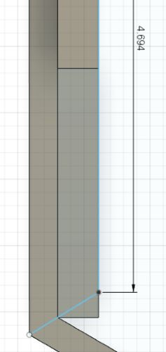
I realized that I had set the desired diameter as the radius for both designs, meaning everything was too large. I went through and redid the original model by deleting everything back to the sketch base and then rebuilding it. Here are some pictures and dimensions:
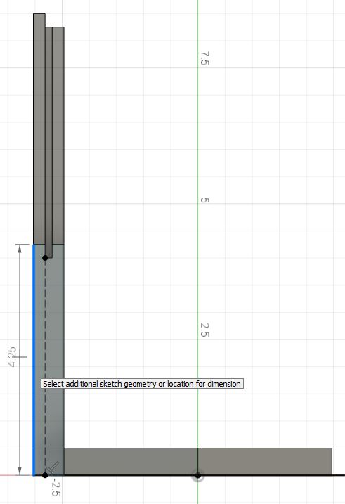
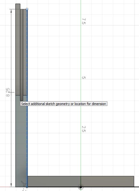
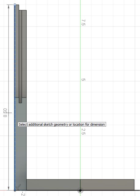
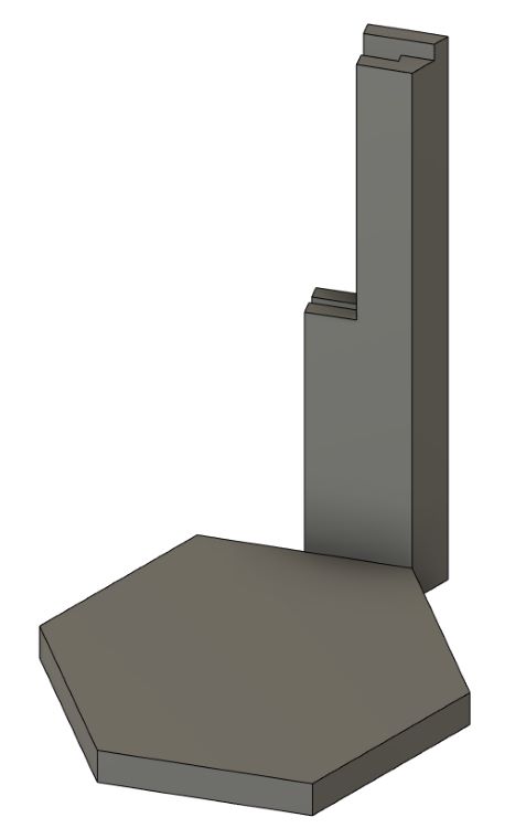
And ended up with this:
I also redid the lid:
And got this:
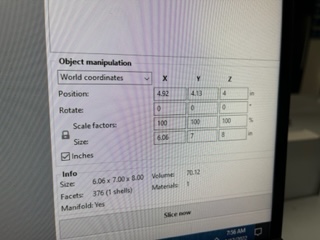
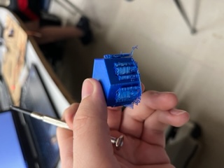
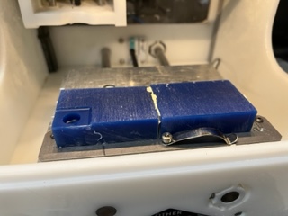
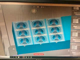
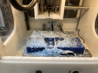
3D Printing Failure
Once done with these models, I brought them into Prusa Slicer and it said the print would take over a day, something which I was not willing to do.
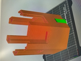
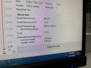
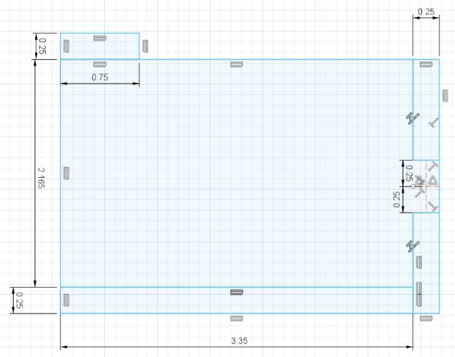
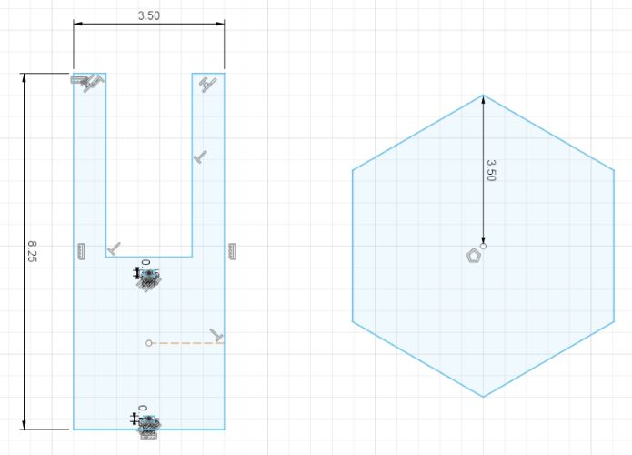
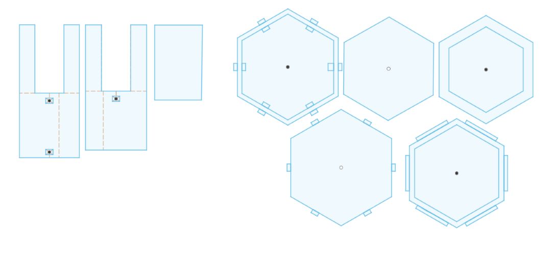
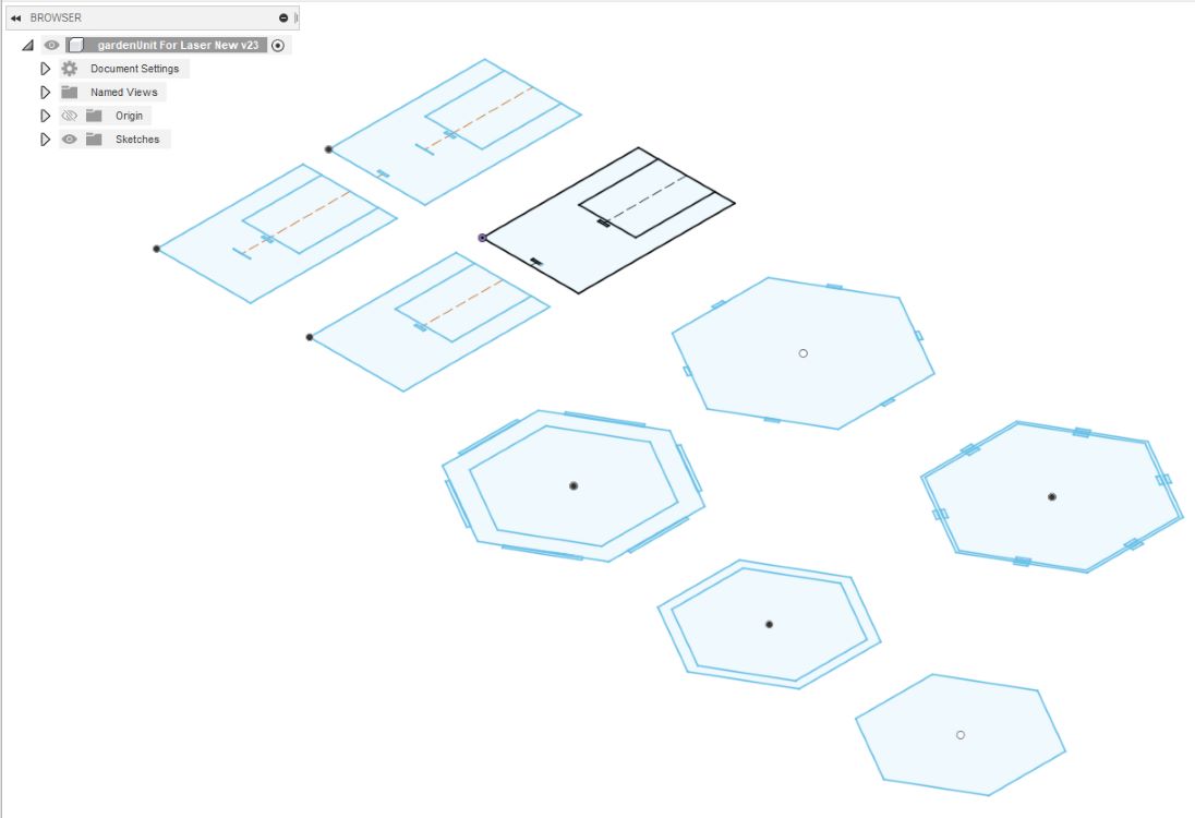
I decided to redesign it to make it so it could be cut on a laser cutter.
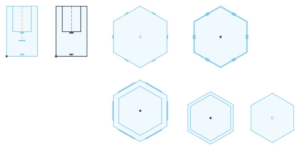
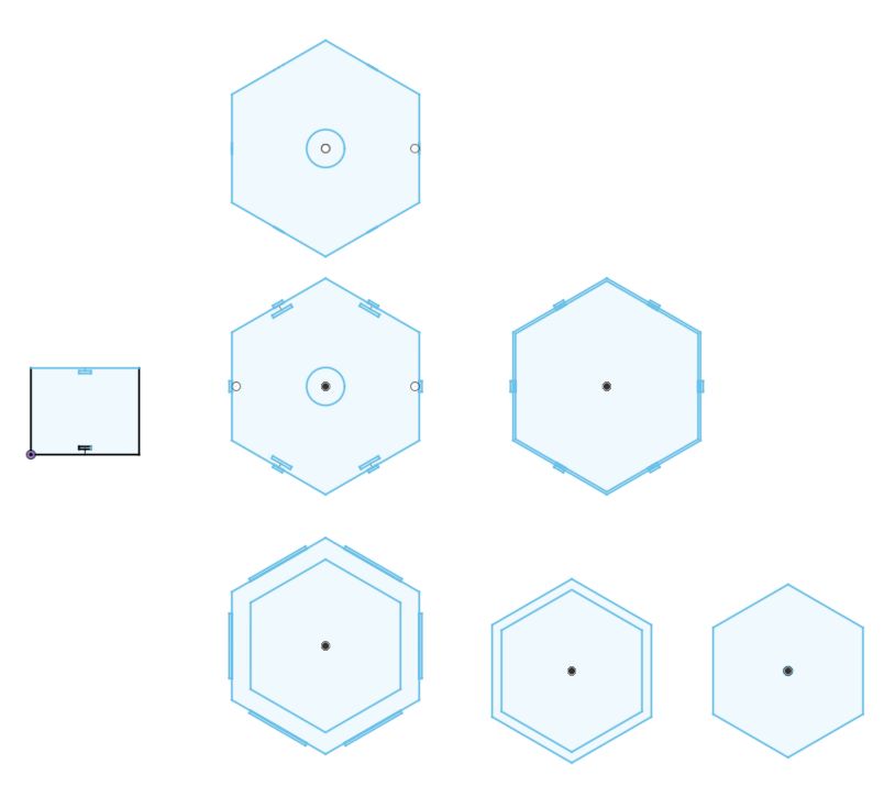
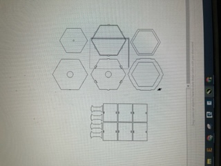
Here are images of my design process:
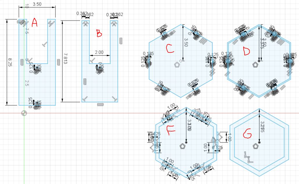
In this image:
A - an outer panel that will be on the outside of the hexagon
B - an inner panel that will be on the inside of the hexagon past the acrylic panel
C - the base plate that connects to the outer panel and creates a floor inside the unit
D - The thin lining that goes between the outer and inner walls; where the acrylic windowing will sit
F - (Apparently I forgot to add an E) main roof piece, sits on top of the inner walls and fills the space between the top of the outer panels
G - a smaller piece which goes on the underside of the roof panel to hold the acrylic in place on top
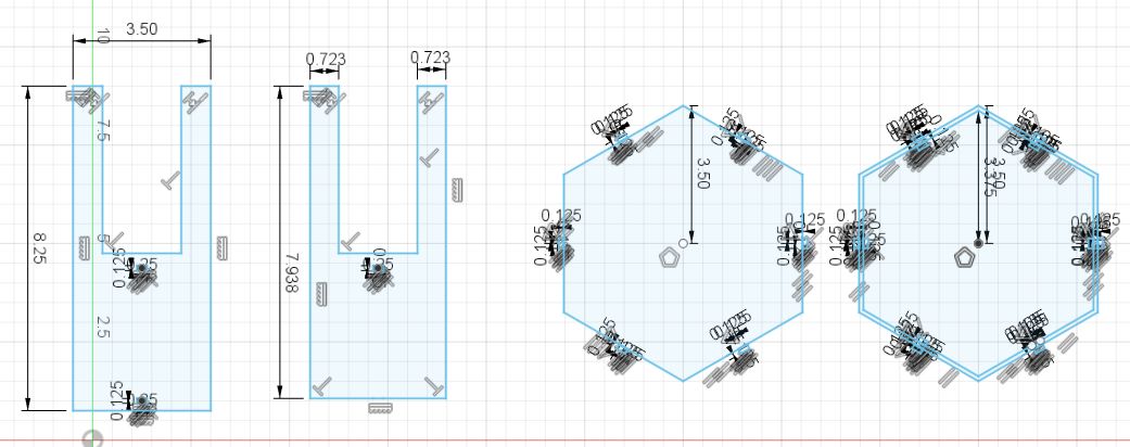
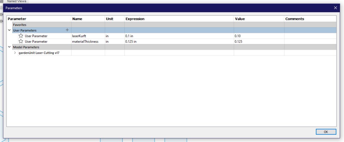
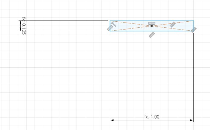
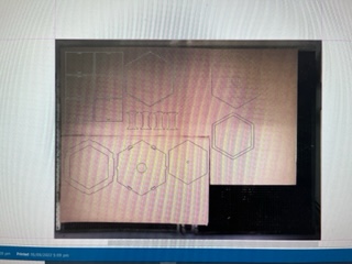
And then I implimented parameters:
And it turned out like this:
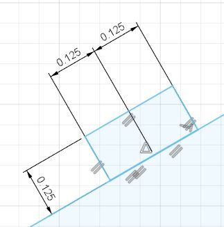
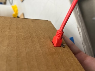
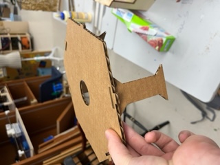
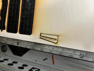
I went and cut this, but they failed horribly. I entirely mis-measured kerf as well as having the wrong concept of what kerf was in my head, I forgot the for cuts it would only be half of the kerf effecting the cut and not the entirety of the kerf doing so. Even still, here are some images of those cuts:
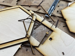
This above image shows the skinny part of the design that got completely burned and destroyed in the laser cutting process. I ended up completely redoing all the dimensions as to make the garden unit much bigger since I wasn’t restricted to time and also to add proper constraints and parameters this time.
Testing the New Design
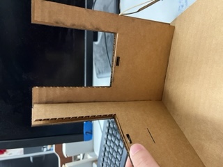
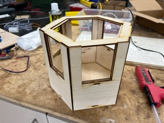
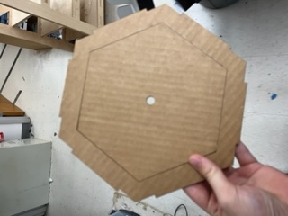
I used a caliper to test the material thickness of the wood and then also measured the kurf of the cutter on eigth inch wood. I modified the parameters as such and then sent the file to Corel as a .dxf. I then removed unneeded construction lines and sent to the cutter. These cuts turned out perfect so I assembled the build as a whole using hot glue.
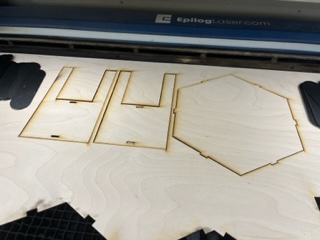
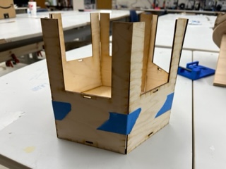
I first taped the walls together to hold them in place for me to glue them which worked well.
While this didn’t include all the parts I would have eventually, it still proved I had the parameters and dimensions correct, so then I began designing the rest of the components.
June 1st, 2022
Finishing the Designs
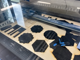
I followed the same process as I had prior but armed with new knowledge of my errors to design the rest of the garden unit pieces.
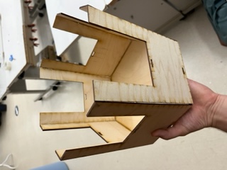
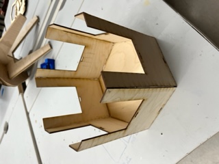
And then I went to cut these parts via the same process as before. They came out well, but there were 2 glaring errors.
- Inner pieces were the same overall height as the outer pieces, and as a result they floated off the bottom of the garden
- The inner pieces when added to the inner ring collided and wouldn’t fit (at their edges)
To fix the second problem, I extruded the components I was having issues with to their exact size that they would be after kerf, and created a parameter using that found value. I then modified the parameter according to the value I found. The downside of using this method is that I would have to remeasure whenever I change the material thickness, however what was good is that it would theoretically solve my issue without having to figure out fancy math.
To fix the first problem, I modiifed some of the dimensions of the inner plates.
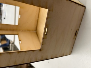
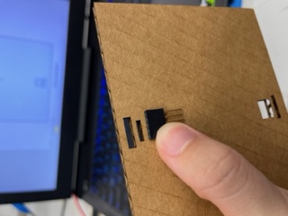
With these changes, I wanted to do a quick cut to test these new pieces. I cut 2 of the part. They fit nicely and the only remaining issue was the soil moisture sensor slot being too small.
Due to our large 50 watt laser being broken at the time, I decided to work on a different part of my project, that being development on the software/raspberry pi side of my project.
Unity on Pi
I made a blank Unity project and adding a spinning cube, the cube having this code:
this.transform.eulerAngles = new Vector3(this.transform.eulerAngles.x, this.transform.eulerAngles.y + 1, this.transform.eulerAngles.z);
And I set the build target to Linux:
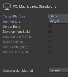
And the build generated these files:
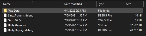
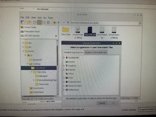
I then sent these to my Pi via USB stick. I downloaded the files on the Pi. I attempted to run each of the files from the build with no sucsess. Each time it would ask me to choose an application to run my program with, which nothing could be used to do so.
With this failure, I did some research and from what I could find Unity games couldn’t be used on a Raspberry Pi without strange and complex workarounds, and given the time crunch, I decided to ditch Unity and to use Tkinter to develop a program.
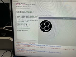
TKinter Program
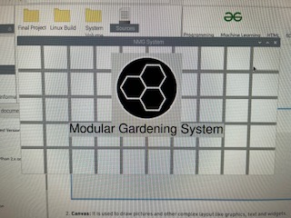
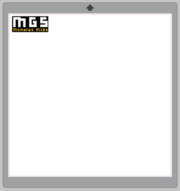
I used the website here to help me start building up my Tkinter program. I created a basic window. I used a tutorial here and a stack overflow forum here to get my project’s logo to appear:
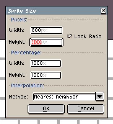
I then added some title text under that logo. From here, I wanted to have a background image. I used a program called Aseprite to design a 40x20 background image which I eventually scaled up to 800x400, the resolution of my program. It came out like this:
I sent this on a USB stick to the Pi and changed the background. I also added title text for the name of my project and used documentation from here on how to size my labels and set their font. I then added a ‘welcome’ button which the user will press in order to view the rest of the program. From here, I made a seperate “screen” that would display once the welcome button was pressed. It would delete all of the objects from the first screen and create the new ones. In this new screen there would be the water tank status, the current soil moisture, and a button which would allow you to turn the pump on and off.
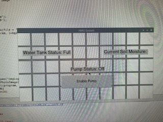
I then programmed it so that the text in that second screen could be changed based off events.
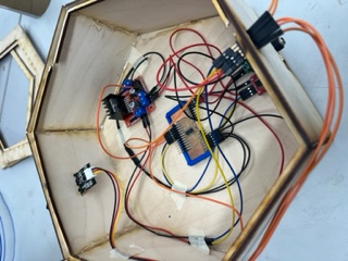
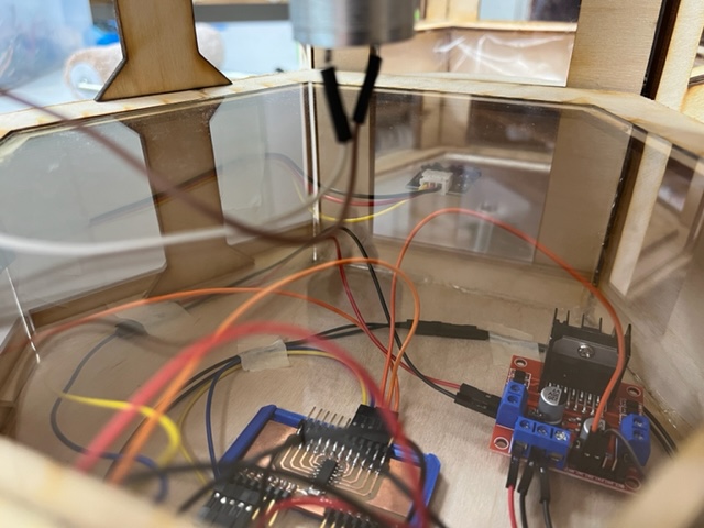
Wiring & Electronics
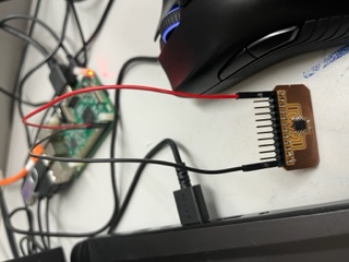
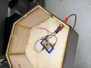
To begin, I wanted to use Rx and Tx from a custom mega board to communicate with my Pi. I did some research and found that I could in fact do that, but that the Pi only had one rx and tx. I wanted to use my old all-purpose board which I alredy had milled to control my system. I got it out and began wiring the sensors and such to it, I also grabbed an L298 motor driver which would be used for my pump.
I needed the following on my Tiny:
UPDI Rx Tx VCC Ground Output 2 Inputs
PA1, PA3, and PA2 on the Tiny could be used for my Ouput and Inputs whilst every other pin would be occupied by utilities. I was lucky that my all-purpose board could in fact carry all of my electronics, however I was concerned about the power consumption. Even still, I began wiring my components. Using my KiCad schematic, I decided on the following:
PA1 - Soil Moisture Sensor PA2 - Water Level Sensor PA3 - Motor Driver Control
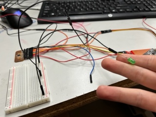
And I wired accordngly. I also wired it to my SAMD to be programmed. In the process I made my SAMD a programmer by reassigning the programmer code from Week 14. Additionally, I jumped the programmer’s ground to a breadbord to allow for more grounds, and I hooked an LED from where the motor driver’s output would be to the newly established breadboard ground. I wrote the following code (below) and plugged in my programmer, sent the code over and the light did indeed turn on:
float currentSoilMoisture = 0;

void setup() {
  Serial.begin(9600);
  pinMode(2, INPUT);
  pinMode(3, INPUT);
  pinMode(4, OUTPUT);
}

void loop() {

  digitalWrite(4, HIGH);
  return;
  currentSoilMoisture = analogRead(2);

  //Soil Moisture Data Calculation
  for (int i = 0; i <= 100; i++)
  {
    currentSoilMoisture = currentSoilMoisture + analogRead(2);
    delay(1);
  }

  currentSoilMoisture = currentSoilMoisture/100.0;
}
This proved to me that having both the sensors and an LED toggled wasn’t too much of a draw for the Tiny, as previously having 2 seperate sensors running for my caused both to stop working for some reason. I then modified my old all-encompassing code to fit my new needs (Driver instead of a Relay) and had this:
const int waterLevelPin = 3;
const int soilMoisturePin = 2;
const int driverActivation = 4;

int counter = 0;
float currentSoilMoisture = 0;
float currentWaterLevel = 0;

void setup() {
  pinMode(driverActivation, OUTPUT);
  pinMode(hearbeatLight, OUTPUT);
}

void loop() {
  counter += 1;
  delay(125);

  // Driver Check
  if (counter % 40 == 0){
    digitalWrite(driverActivation, HIGH);
  }
  else if (counter % 70 == 0){
    digitalWrite(driverActivation, LOW);
  }

  //Soil Moisture Data Calculation
  for (int i = 0; i <= 100; i++)
  {
    currentSoilMoisture = currentSoilMoisture + analogRead(soilMoisturePin);
    delay(1);
  }

  currentSoilMoisture = currentSoilMoisture/100.0;

  if (currentSoilMoisture > 400){
    //Soil is moist
  }

  //Water Level Data
  int currentWaterLevel = analogRead(waterLevelPin);

  if (currentWaterLevel > 10){
    //Tank full
  }

  // Counter Reset
  if (counter >= 71){
    counter = 0;
  }
}
I pushed this code and the light reacted accordingly. With this, I wanted to work on the L298 motor driver. This would be what allowed me to toggle the pump. I looked up some documentation on the wiring of one and followed this.
June 2nd, 2022
Now it was the second. Today, I want to get the following done:
- Fully functioning electronics (Sensor readings and driver toggle)
- Serial communication between Pi and Tiny
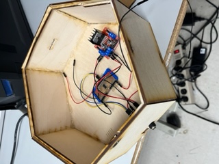
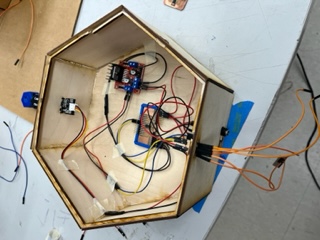
To begin the day I grabbed the cardboard sheet of electronics that I had and gave power to them to test mainly the motor driver.
With everything wired, I plugged it all in. Nothing was happening. I looked here and after a bit of reading, I realized that only either IN1 or IN2 could be HIGH at one time or else it wouldn’t move, so I unplugged the IN2 that was on the breadboard and the pump began working, however, it never turned on/off, but rather, was always on. I modified the wiring so that the UPDI after 10 seconds of power would become an output from the chip. The only thing is that the pump would be on for the first seconds, this was the last issue that I needed to fix.
In the mean time, knowing that Doctor Harris would arrive at noon, I decided to work a bit on the serial sending of the data as well as the receiving. I modified the code to do so. I also stole some code from my networking week project. The only remaining issue I was having was sending multiple ints in between parsing characters through Serial.
Once Dr. Harris arrived, I spoke to him about the driver, and from his advice I pulled the second in pin to ground and my system worked:
And here was the code:
const int waterLevelPin = 3;
const int soilMoisturePin = 2;
const int driverActivation = 4;

int counter = 0;
int altCounter = 0;
int pumpOn = 0;

float currentSoilMoisture = 0;
float currentWaterLevel = 0;

bool enabled = false;
bool enabledViaToggle = false;

void setup() {
  pinMode(driverActivation, OUTPUT);
  pinMode(waterLevelPin, INPUT);
  pinMode(soilMoisturePin, INPUT);
  Serial.begin(9600);
}

void loop() {
  if (Serial.available()== 1){
    // If receiving info
    int incoming = Serial.parseInt();
    if (incoming == 1){
      enabledViaToggle = true;
      digitalWrite(driverActivation, LOW);
      altCounter = 0;
      pumpOn = 1;
    }
  }

  counter += 1;

  if (enabledViaToggle){
    altCounter += 1;
  }

  delay(125);

  if (altCounter % 30 == 0 && enabledViaToggle){
    enabledViaToggle = false;
    digitalWrite(driverActivation, LOW);
    pumpOn = 0;
  }

  // Driver Check
  if (counter % 40 == 0 && !enabledViaToggle){
    digitalWrite(driverActivation, HIGH);
    pumpOn = 1;
  }
  else if (counter % 70 == 0 && !enabledViaToggle){
    digitalWrite(driverActivation, LOW);
    pumpOn = 0;
  }

  //Soil Moisture Data Calculation
  for (int i = 0; i <= 100; i++)
  {
    currentSoilMoisture = currentSoilMoisture + analogRead(soilMoisturePin);
    delay(1);
  }

  currentSoilMoisture = currentSoilMoisture/100.0;

  //Water Level Data
  int currentWaterLevel = analogRead(waterLevelPin);

  String parserer = "$";
  String output = "ADD STRING";

  Serial.print(output);

  // Counter Reset
  if (counter >= 71){
    counter = 0;
  }
}
I didn’t manage to finish Serial quite yet but I moved onto finishing the Garden unit.
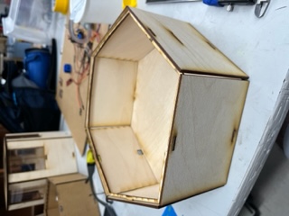
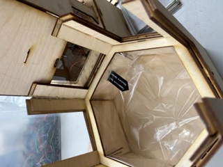
Garden Unit Development
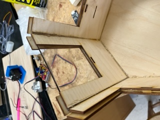
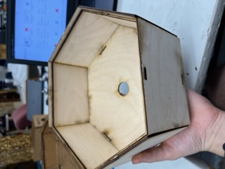
After some minor adjustments to my fusion file, I went to cut some test pieces out of wood. I cut 2 sets of walling as well as the base plate and the inner ring as well. These pieces however turned out very poorly. The scale of the tabs and holes for those tabs were completely off and I needed to sand and use a hammer to get the pieces in, and even still, they didn’t feel super solid. I went back to my fusion file and added some leway to my dimensions so that the pieces would have some space to move. I then cut these. These pieces fit together very well.
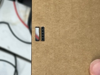
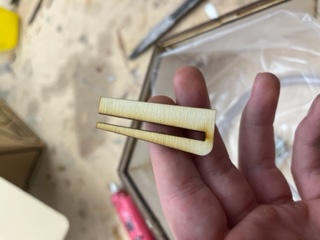
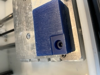
The soil moisture sensor also fit together well:
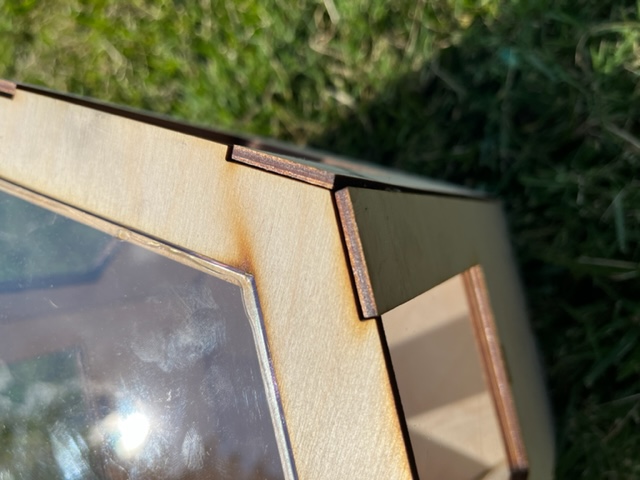
I then cut the remainder of the pieces and walls. I began by gluing together the lid and the underside of the lid together (the underside meant to hold the acrylic in place)
I then glued the remainder of the walls in and put the lid on the top.
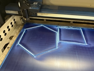
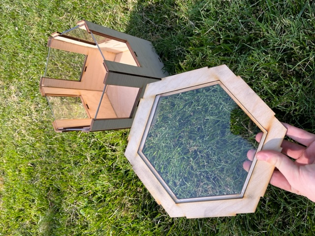
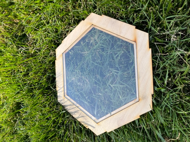
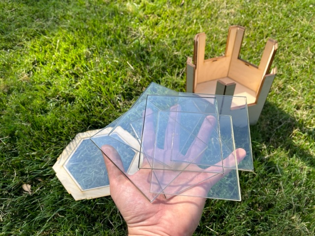
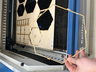
I then wanted to cut my acrylic panels next. I layed a large sheet of plexiglass into the cutter and pulled up the files. I cut the hexagonal roof and also one of the side pieces (a prototype of it).
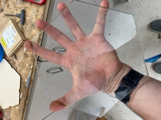
The hexagonal roof came out well.
And so I glued it into the lid.
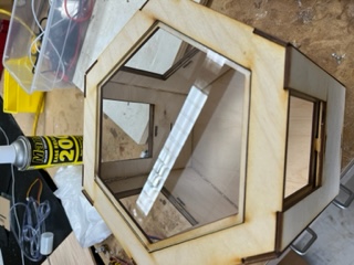
The side panel came out nicely:
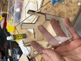
And it fit well into the side.
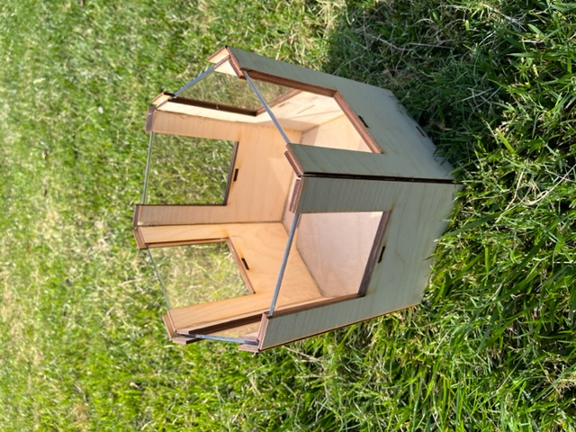
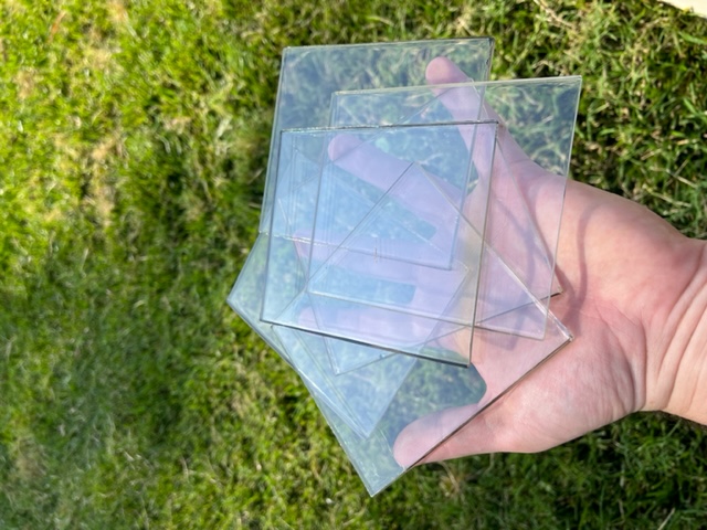
I then cut the remainder of the panels:
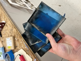
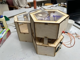
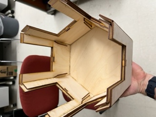
And placed them in
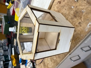
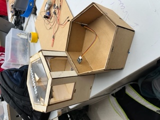
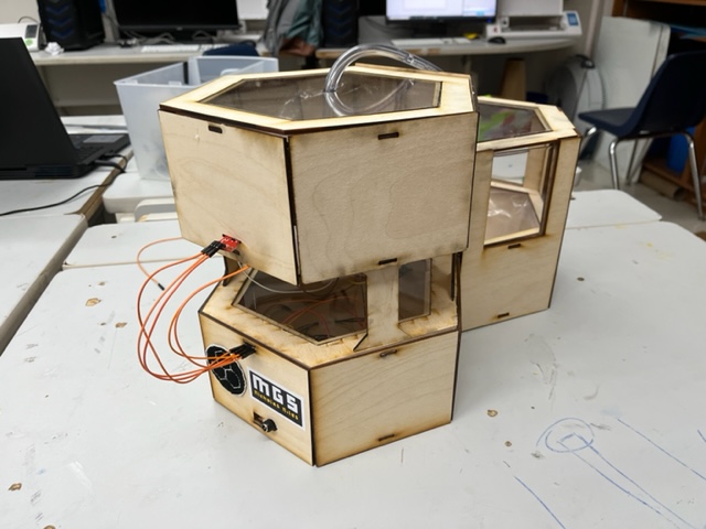
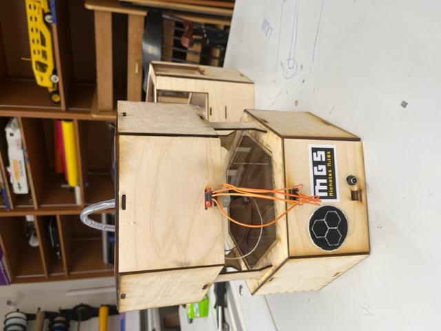
And with that, the Garden Unit was finished!
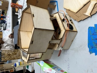
Hero Shots
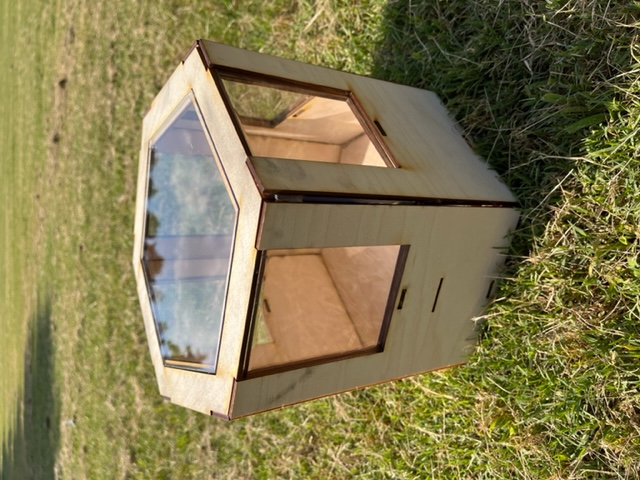
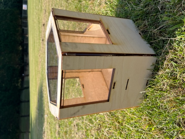
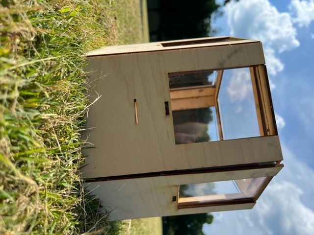
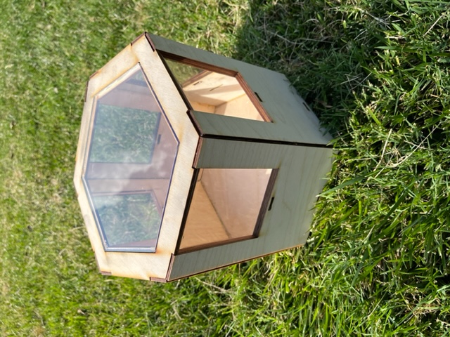
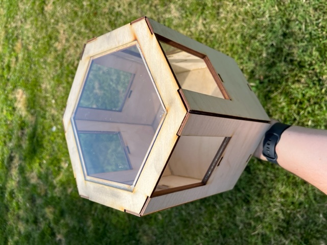
And with that the garden unit, lots of the electronics, and June 2nd came to a close.
June 3rd, 2022
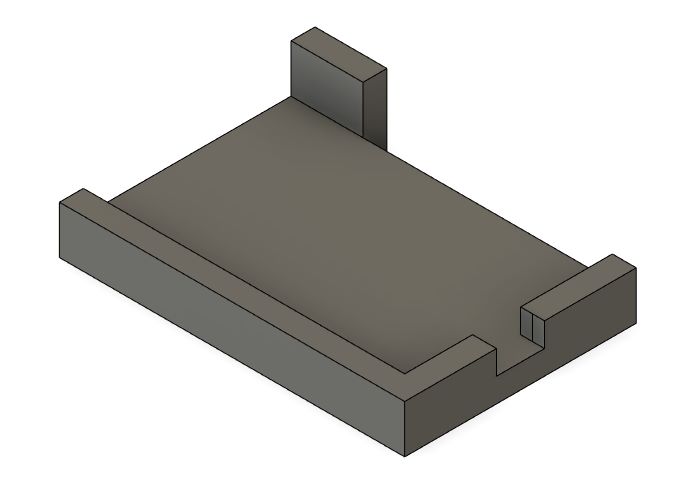
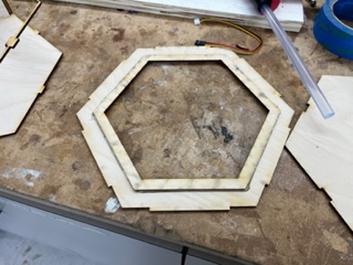
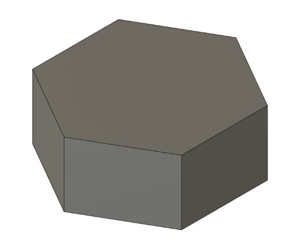
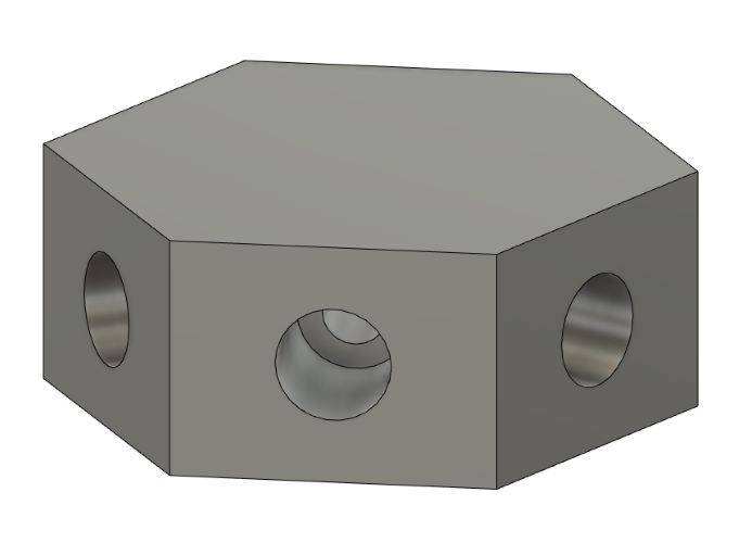
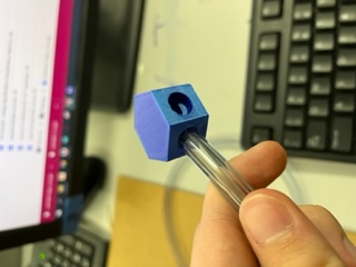
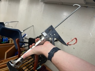
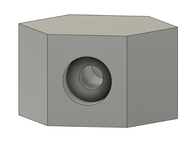
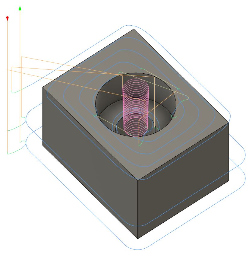
Today I only had 3 hours to work because I came in late. I decided I wanted design the pipe junctions where all the pipes would meet, and then to print them on the 3D printers. I wanted to create a hexagonal conjunction that allowed for 6 to plug in and one to come out of the bottom. I began by drawing a hexagon. I measured the pipes to be .355 inches in diameter. I also drew the hexagon to be 1 inch radius.
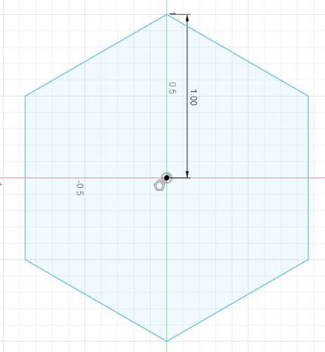
I then extrued it to be 0.75 inches tall.
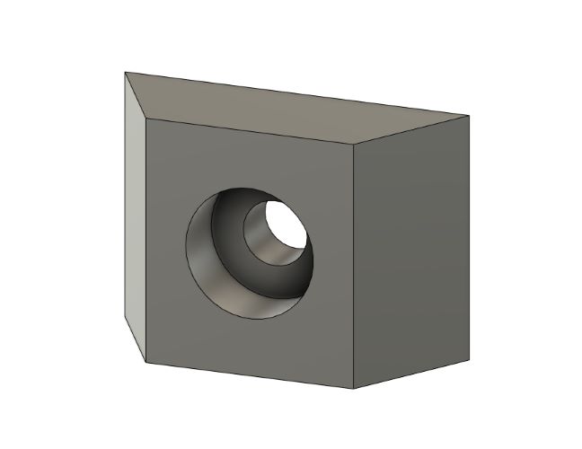
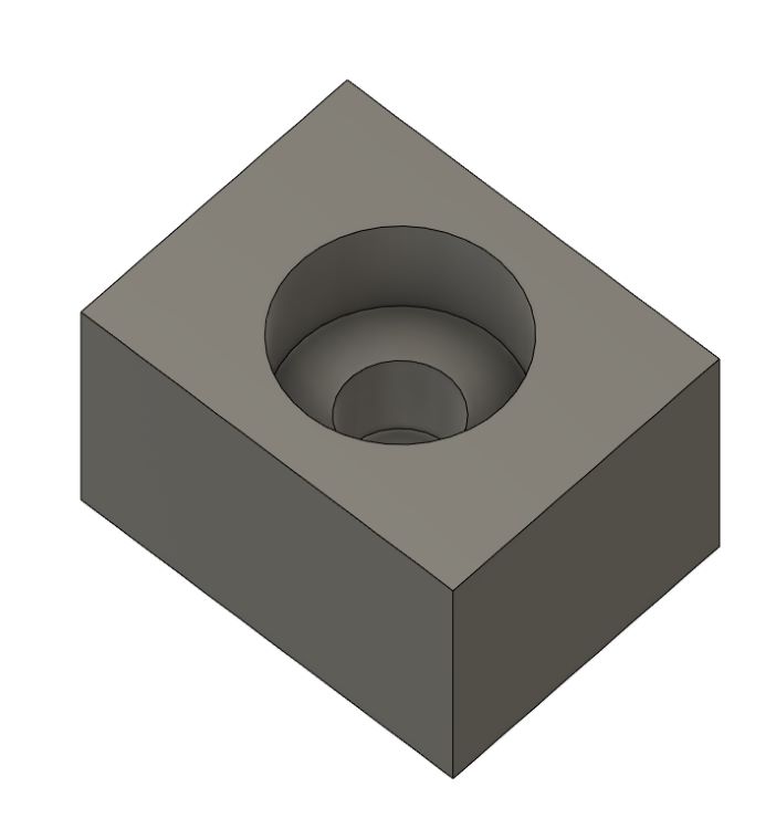
And added a circle the diameter of the pipe to the center of the side.
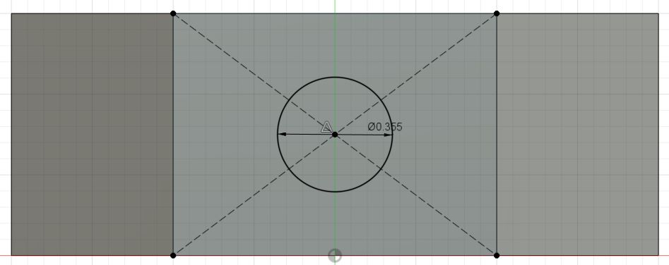
From here I wanted to add a second circle inside the first so that the pipe would have a place to rest. I measured the inner diameter of the tube to be .2 inches so I added a circle accordingly.
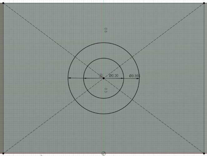
I then extruded the circles as holes.
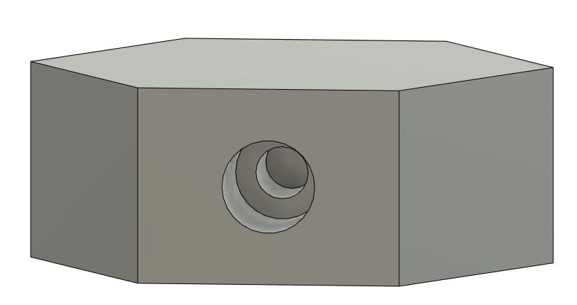
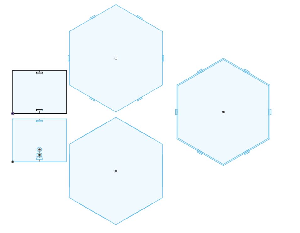
I then procedeed to mirror this design across the entire shape. I did so for each by adding a midplane and mirroring the features.
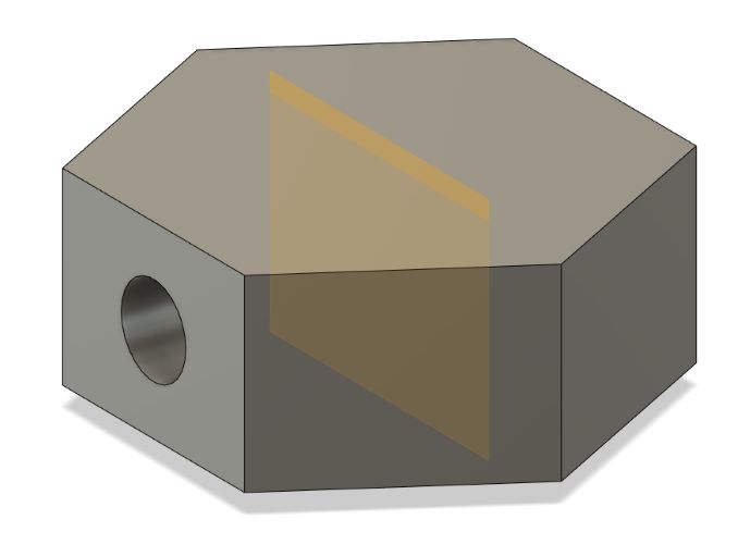
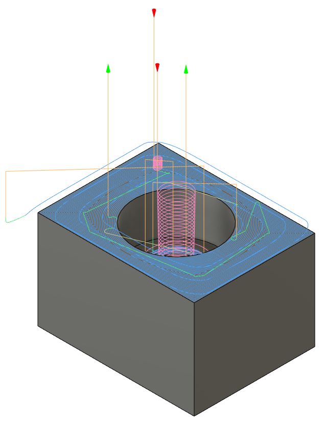
It ended up looking like this:
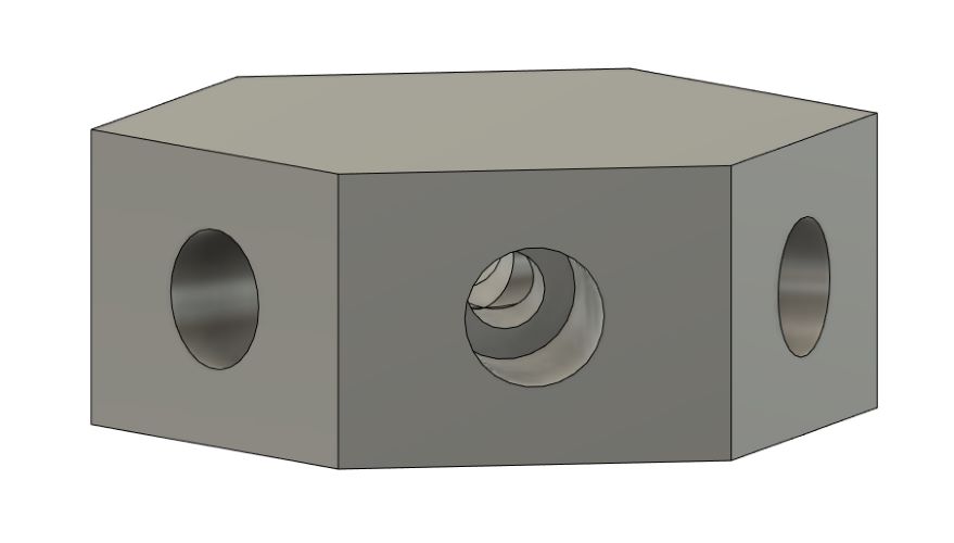
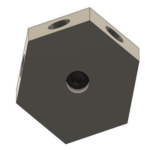
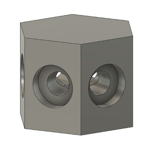
From here, I added a center circle with the same inner and outer hole for the underside pipe:
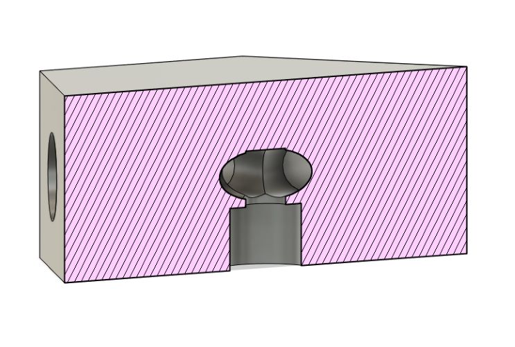
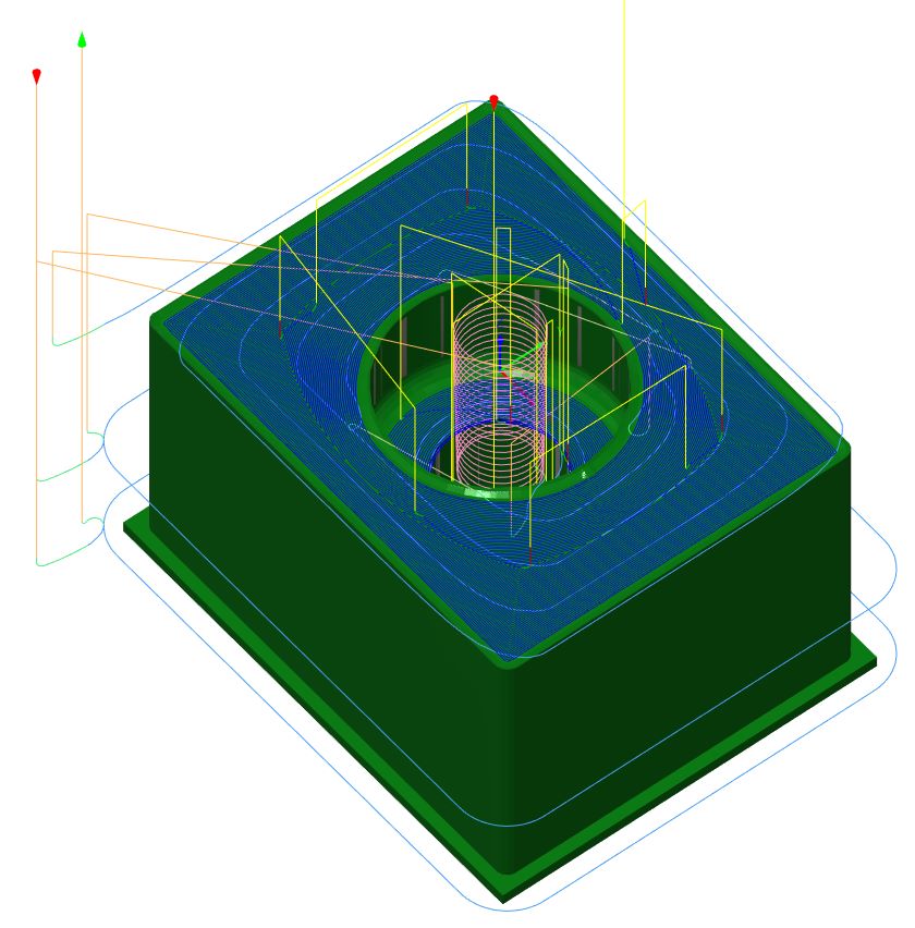
Here is a crosssection:
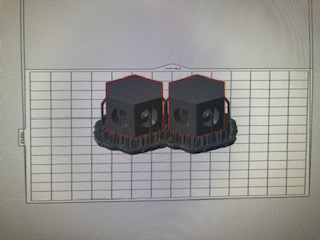
And here’s a final image:
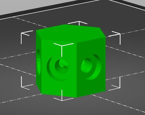
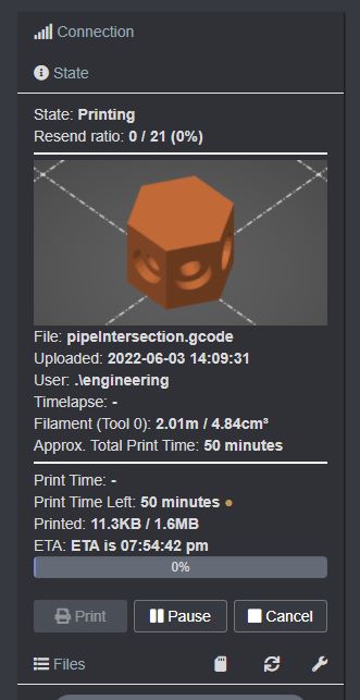
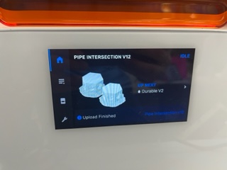
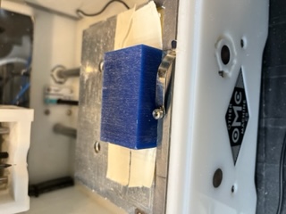
And I went to print one of them. However, once in PrusaSlicer, I realized that I had set the radius of the hexagon to 1 inch and not the diameter like how I hoped, so I went back into fusion and adjusted all the dimensions to fix this and got this:
And it worked well in Prusa
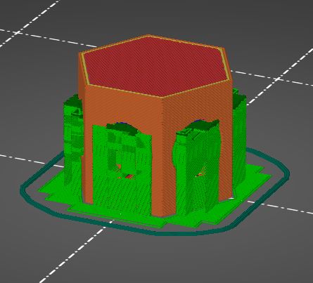
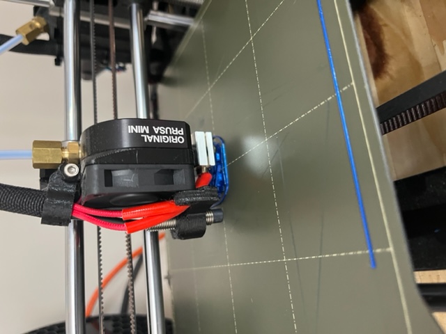
And I printed it
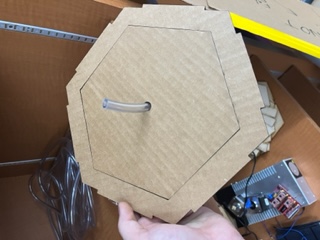
In the Mean Time
I decided to work on the Main Unit’s shell whilst waiting for my pipe intersection to print. I began by making a copy of the Garden Unit’s file and modifying it. I made the following changes:
- Shortened the wall height down to the place where the acrylic used to begin
- Removed the inner panels
- Added a port hole for the RasPi power port
- Added a port hole for the motor driver power
- Made the roofing solid without a window
And it looked like this:
I also inputted the kerf again into my parameters and also the thickness of some wood I had. All I needed to do now is to add a holder for the touch screen and mounts on the top for the water tank (which will be detachable and designed seperately).
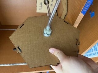
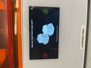
Pipe Intersection Finished Printing
By now the 1 hour print of the pipe intersection was done. I took it off and cleaned it up (there were lots of supports), however it looked like this initially:
So I cleaned it up:
And tested if pipes could fit and it was a little bit too small, so I was going to have to work on it. I changed the diameter of the hole from .355 to .4 and changed the depth in which the pipes go into from -.1 to -.2. I also changed the radius of the whole shape to .65. With these changes, I began the reprint.
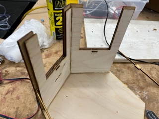
Further Work on the Main Unit
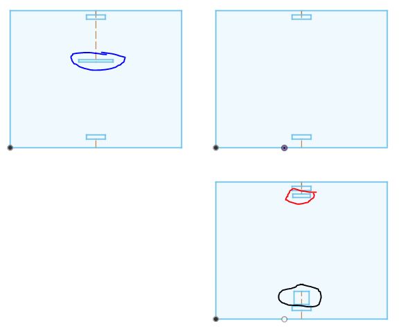
I furthered development on the Main Unit, now adding panels for the screen, and also adding other necisary holes for wiring/electronics. Below is an image of those panels with letter labling which explains what each is below:
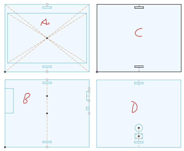
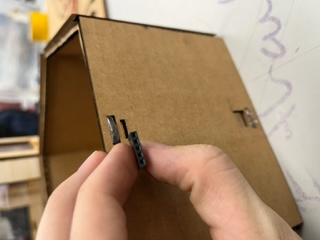
A. Where the screen will fit in. B. A generic side plate however it has a hole for the HDMI to come off the screen and ALSO it includes another hole for the HDMI cable to go back into the Unit C. C is a completely generic plate that’ll make up the remainder of the sides of the casing D. D is a plate that will go on the back of the unit, it has holes for the following:
- Jumpers at the top under the tab slot
- Motor driver plug hole (circle)
- Lastly the square under that cirlce allows for the RasPi’s plug to go through
With these done I called it a day and planned to run test cuts and potentially the final build tommorow. I also planned to document and review the outcome of my pipe intersection tommorow as well.
June 5th
Today I had a few goals:
- Purchase the plants for my gardens
- Finish the CAD work on the Main Unit and Water Tank above that
- Finalize the code for serial communication between the Pi and the Tiny
- Develop slide/video
I first began developing my slide. I looked at Graham Smith’s final project page to get an idea. I put the title of my project with my name at the top, and wanted to leave space for each skill I incorporated.
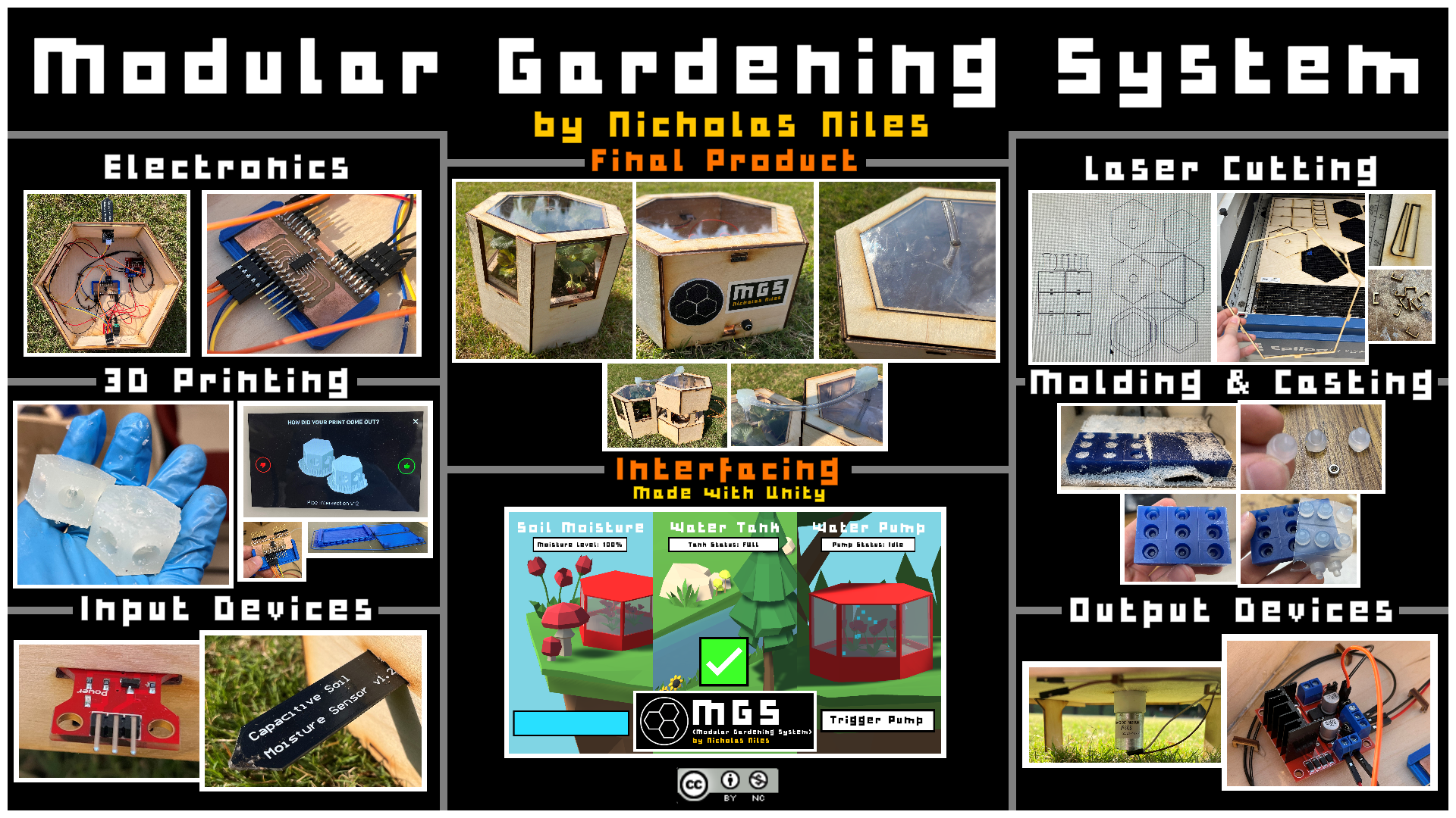
This early version shows my idea: having an image for each week I incorporated. I later also added my licensing to the top left.
Later that night, I did some thinking. I reviewed past year’s student’s finals from our lab. I looked at 5+ videos and presentations, and also watched Vincent Zhou present his final to Dr. Gershenfeld from some years back. After watching all of these, I was very motivated, and also really wanted to step up my game. I realized that the one major wow factor of my project, which I previously had presented to Dr. Gershenfeld, that being Unity, was something I hadn’t included simply because of it’s malfunction on a Pi. I realized that voiding it for this reason was silly and that I should make some alterations to include Unity as it would make my data analysis and display for my final a lot more impressive and developed. All I’d have to do is:
- Attach my Tiny board to my SAMD serial translater
- Solder that to a USB plug that could be plugged into from outside the hexagon
- Program serial port data reading into Unity and attach that to the program I already have
- Remove the screen
- Make edits to my Main Unit design
- Design a quick 1614 chip breakout board so I have more pins then Mill, Solder, and Construct that
All of this wasn’t too much either, and it would really up my project tons.
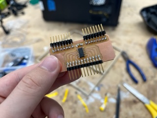
I first drew up a brand new PCB schematic. This would include a 1614 and a ton more pinouts than before for VCC and Ground. The reason I did this is because I barely made it with the prior all purpose board, and I wanted to have a board which had many spare digital/analog pins as well as VCC/Ground in case that I needed more or if I wanted to add more sensors. I recorded a video of me designing the board which will be includded in the final video which is why I didn’t document the process since I was recording. It turned out like this:
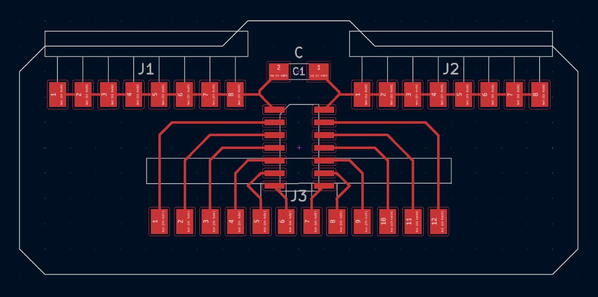
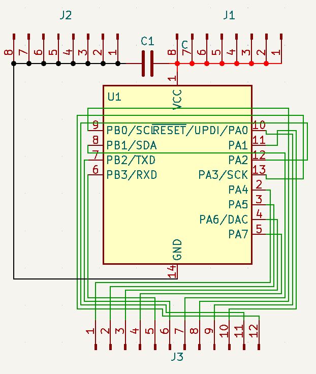
While the wiring in the schematic view looks rather awful, it is due to a major mixup in the wiring early on which I didn’t think was necisary to visually fix. Overall, however, I had a finished board that just needed milling.
Unity Serial
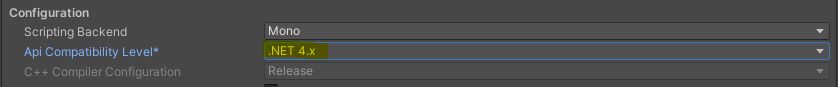
After doing a bit of digging I found on the Unity Forums someone who had similarly been reading serial through the engine. Their post can be found here. Reading this page taught me something super important that I had been looking for a solution too, that being that I could print normally and it wouldn’t be sent (or in Unity fully read) until I do print line. This solved my data problem. With that in mind, I re-wrote some code in my Unity program. I was however getting an error for the “using System.IO.Ports;” in my code. After some digging on the Microsoft Documentation and eventually this page I found I needed to run a package manager command to install the required dependencies. I ran Install-Package Microsoft.Windows.Compatibility -Version 6.0.0 in the package manager console to correctly install the packages and this fixed my issues. For some reason, the “SerialPort” script from that library still wasn’t working. I found here that I needed to switch the API compatibility in Unity from NET 2.0 to NET 4.0 and this fixed my issues.
Overall, the only 3 lines of code needing to get serial to work were this:
using System.IO.Ports;
SerialPort stream = new SerialPort("COM4", 9600);
string value = stream.ReadLine();
From here I refactored my code to include this. I decied I’d use the following format to send data:
&soil moisture@water level@pump on/off&
and this would of course be sent in Arduino like this:
&

soil moisture

@

water level

@

pump on/off

&

PRINT LINE
and of course wherever I put the text in the references above there would be actual numerical values. It was important to finish this before implimenting the code that way I wouldn’t have to figure it out as I go or have to reprogram my chip later. With this data formatting in mind I developed the new code.
//Data Recieval
        string value = stream.ReadLine();

        string[] recievedData = value.Split('&');
        string[] subData = recievedData[0].Split('@');

        //Soil Moisture
        float soilMoisture =float.Parse(subData[0]);

        soilMoisture = Mathf.Abs(100 - (((soilMoisture - 316) / 359) * 100));
        soilMoisture = ((Mathf.RoundToInt(soilMoisture * 100)) / 100);

        if (soilMoisture < 0)
        {
            soilMoisture = 0;
        }
        else if (soilMoisture > 100)
        {
            return;
            soilMoisture = 100;
        }

        Update_MoistureVisual(soilMoisture);
        sensorText.text = "Soil Moisture: " + soilMoisture.ToString() + "%";

        //Water Level
        float waterLevel = float.Parse(subData[1]);

        //Pump Toggle
        float pumpEnable = int.Parse(subData[2]);
        bool pumpOn = false;

        if (pumpEnable == 1)
        {
            pumpOn = true;
        }
        else
        {
            pumpOn = false;
        }
Above is my updated Update() function. It reads the data and processes it. From here, all I need to do is run proper math on the recieved water level value and also to update the Arduino code. From here however I wanted to create a visual. I decided for the visual I wanted to achieve something for each component of my project. I decided on having both a UI portion as well as a 3D portion that were both effected by the physical sensors/output device. To do this I wanted to create 3 seperate in game cameras that would represent what was happening.
Again, all of this was recorded for my final video so I wasn’t documenting the process.
June 6th
Today I got right to work. I finished the entire UI and backened functionality in Unity. The final UI product looks like this:
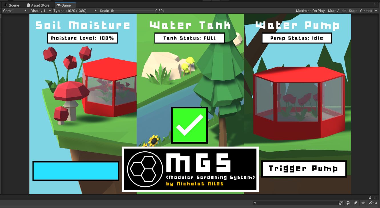
Again, while I didn’t document this process, it was all recorded and will be posted. Additionally, you can look at Week 14 where I document my initial interfacing in Unity step by step. From here I wanted to further develop my Arduino code to fit my new system. I just simplified the code and added the serial functionality in line with the serial techniques I mentioned in yesterday’s documentation. It turned out like this:
const int waterLevelPin = 3;
const int soilMoisturePin = 2;
const int driverActivation = 4;

int counter = 0;
int timeToggledAt = 0;
int timeToDisableAt = -1;
bool pumpOn;

void setup() {
  pinMode(driverActivation, OUTPUT);
  pinMode(waterLevelPin, INPUT);
  pinMode(soilMoisturePin, INPUT);
  Serial.begin(9600);
}

void loop() {
  if (Serial.available()== 1){
    int incoming = Serial.parseInt();
    if (incoming == "enablePump"){
      TogglePump();
    }
  }

  counter += 1;

  delay(125);

  if (timeToDisableAt == counter){
    timeToDisableAt = -1;
    digitalWrite(driverActivation, LOW);
    pumpOn = false;
  }

  //Soil Moisture Data Calculation
  for (int i = 0; i <= 100; i++)
  {
    currentSoilMoisture = currentSoilMoisture + analogRead(soilMoisturePin);
    delay(1);
  }

  currentSoilMoisture = currentSoilMoisture/100.0;

  //Water Level Data
  int currentWaterLevel = analogRead(waterLevelPin);

  Serial.print('&');
  Serial.print(currentSoilMoisture);
  Serial.print('@');
  Serial.print(currentWaterLevel);
  Serial.print('@');

  if (pumpOn){
    Serial.print('1');
  }
  else{
    Serial.print('0');
  }

  Serial.println();
  // Counter Reset
  if (counter >= 71){
    counter = 0;
  }
}

void TogglePump(){
  if (pumpOn){
    return;
  }
  digitalWrite(driverActivation, HIGH);
  timeToggledAt = counter;
  pumpOn = true;
  timeToDisableAt = timeToggledAt + 50;
  if (timeToDisableAt - 70 >= 0){
    timeToDisableAt = timeToDisableAt - 70;
  }
}
3D Pipe Intersection
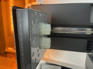
Another piece of my project which I had printed a couple days back was my new pipe intersection. This was now done so I took it off the bed:
And started removing supports for a while. From here I tested it with an actual piece of piping, which fit perfectly:
Milling Issue
I went to mill my new 1614 board now that I was in the lab to realize that the traces were really small. I went back into KiCad and set my minimum trace width to 0.5 from 0.2 and redrew my board. I then plotted and exported this new board to be milled. Additionally I reviewed my Week 13 documentation to find these old rules I wrote for milling:
- Trace Clearence in the Bantim software of 2 mm
- Trace Width in KiCad to 0.5 mm
And I used those. I then milled with these settings and here is how it turned out:
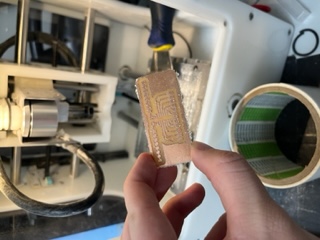
And then I did post processing and it came out like this:
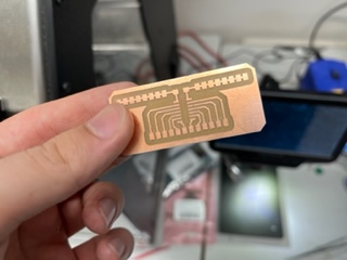
So I soldered the required components and this is how it came out:
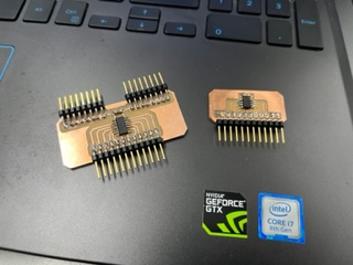
Above is a comparison between my new board (left) with the 1614 to the previous board (right) with the 412 chip.
So then I wired the entire thing based off of my previouse 412 wiring:
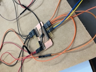
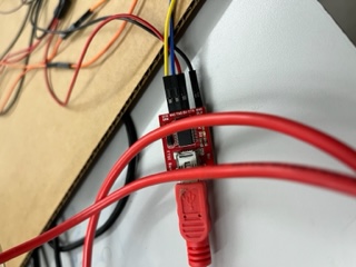
And pushed my latest Arduino code and also converted my SamD to a serial monitor and I opened the Serial monitor with sucsess!!!
So from here I just needed to run my Unity program.
I wired Tx as yellow and Rx as blue. (additional note)
Linking with Unity
I began using Unity to print values to the console. After some work I realized a major flaw in my design, that being that PA numbers on the 1614 and 412 didn’t match, which is why the water level sensor wasn’t properly working. I rewired accordingly however still had an issue, that being that my water level data line ran into my 1614’s Rx pin in my old 412 code since the numbering was different. This meant that I had to go through the whole process of changing my SamD back into a programmer then a serial monitor once more…
SamD Issues
I eventually went through with all of that and changed my code to this:
const int soilMoisturePin = 1;
const int waterLevelPin = 2;
const int driverActivation = 3;

int counter = 0;
int timeToggledAt = 0;
int timeToDisableAt = -1;
bool pumpOn;

float currentSoilMoisture = 0;

void setup() {
  pinMode(driverActivation, OUTPUT);
  pinMode(waterLevelPin, INPUT);
  pinMode(soilMoisturePin, INPUT);
  Serial.begin(9600);
}

void loop() {
  if (Serial.available()== 1){
    int incoming = Serial.parseInt();
    if (incoming == 1){
      TogglePump();
    }
  }

  counter += 1;

  delay(125);

  if (timeToDisableAt == counter){
    timeToDisableAt = -1;
    digitalWrite(driverActivation, LOW);
    pumpOn = false;
  }

  //Soil Moisture Data Calculation
  for (int i = 0; i <= 100; i++)
  {
    currentSoilMoisture = currentSoilMoisture + analogRead(soilMoisturePin);
    delay(1);
  }

  currentSoilMoisture = currentSoilMoisture/100.0;

  //Water Level Data
  int currentWaterLevel = analogRead(waterLevelPin);

  Serial.print('&');
  Serial.print(currentSoilMoisture);
  Serial.print('@');
  Serial.print(currentWaterLevel);
  Serial.print('@');

  if (pumpOn){
    Serial.print('1');
  }
  else{
    Serial.print('0');
  }

  Serial.println();
  // Counter Reset
  if (counter >= 71){
    counter = 0;
  }
}

void TogglePump(){
  if (pumpOn){
    return;
  }
  digitalWrite(driverActivation, HIGH);
  timeToggledAt = counter;
  pumpOn = true;
  timeToDisableAt = timeToggledAt + 50;
  if (timeToDisableAt - 70 >= 0){
    timeToDisableAt = timeToDisableAt - 70;
  }
}
And of course changed the wiring accordingly. I was able to push this code sucsesfully, however, when changing the SamD back into a serial monitor, something went completely wrong, and my SamD was no longer responding in the USB port. The USB port sound wasn’t playing either, meaning it had reverted from a USB device. I followed my Week 4 documentation on prepping a SamD for the USB port and all. I first got the Atmel ICE device and plugged the jumpers in accordingly:
And from there plugged in my programmer:
And attempted to follow the steps to convert it. Everytime I did however, I got tons of errors in the terminal. I tried a second Atmel ICE and it still failed to alter the device. I decided to giveup on the SamD and search for another solution.
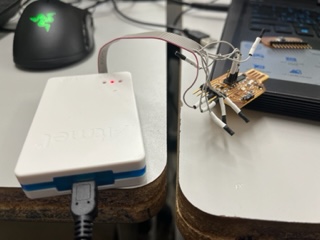
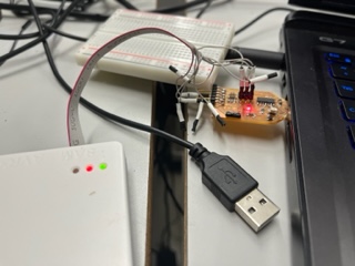
FTDI Saves Me
I remembered back to interfacing week when many people used a small board called “FTDI” in order to read data through the serial port. After speaking with my instructer about the use of one in my final, I decided it was exactly what I needed. My friend Jack Donnelly provided me with one of his old ones to keep. From here I followed the labled pinouts to wire my device. It was SUPER simple and worked first try, this is honestly what I shoud’ve been using the whole time.
Additionally it was perfect because it already had the USB plug setup done for me so I wouldn’t have to do that later. I was super happy with this and it was working.
From here I jumped over to Unity to test it out.
Unity Once More
Once in Unity, I tested the FTDI readings. I was able to grab values to the console, HOWEVER these values didn’t seem to change for some strange reason. Confused, I messed around with my code and read a forum post here which led me to my solution. I added these additional lines:
SerialPort mySerialPort = new SerialPort("COM4");
mySerialPort.BaudRate = 9600;
mySerialPort.Parity = Parity.None;
mySerialPort.StopBits = StopBits.One;
mySerialPort.DataBits = 8;
mySerialPort.Handshake = Handshake.None;
mySerialPort.Open();
string value = mySerialPort.ReadLine();
mySerialPort.Close();
While I don’t understand why this fixed my issues, it did, which I was happy about. I also put the serial reading code into a IEnumerator (Courotine) so that it would run every second instead of each frame, which majorly reduced lag, though I hoped to change this delay later so that you could easier see the transition between value with my sensors. With this done, I was reading values perfectly in the console:
From here, I modified some of the math being run on the values so that it would better represent the values as percents/booleans. With this done, my system (except for the pump aspect) worked perfectly!
And with this I wrapped up for the day. I had made monumental progress towards completion, and now only needed to add the pump functionality and the shell/housing for the main unit!
June 7th
Goals:
- Get the pump functioning (Toggleable from Unity)
- Design & construct Main Unit housing/water tank
- Begin fitting electronics/components
I got to the lab around 11 and have already made monumental progress. It turns out all my code for the pump and all works perfectly ALREADY and I need to make no changes! I tested this by simply hooking up power. Here is it being triggered manually:
And here is a video of it being triggered automatically when the soil is too dry:
I was super happy with this and it also meant all of my electronics work was done, all I needed now was to build the shell!
Designing the Shell
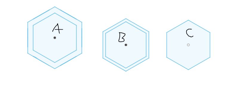
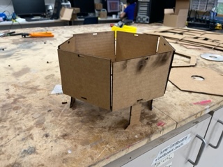
I went back to the shell I had been designing. I decided the way it was was too old and reduntant for my new needs, so I made a new copy of the Garden Unit’s file to begin working on.
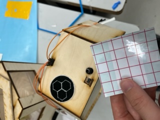
From here, and note that I already removed some parts, I worked on the initial paneling.
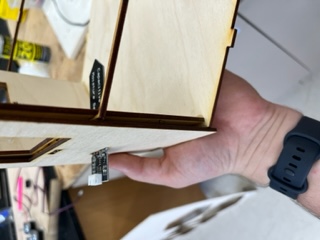
Here are all the panel types. In blue is the whole for the Soil Moisture Sensor to go through to the garden Unit, in Red is where jumper wires will go out of to reach the water tank’s pump and sensor, and in black is where the FTDI plugs in. I also decided to impliment the Acrylic roofing again which can be seen here:
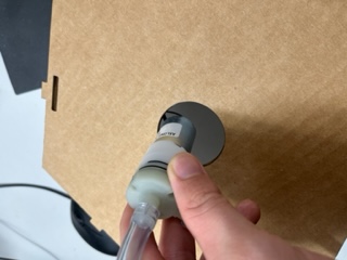
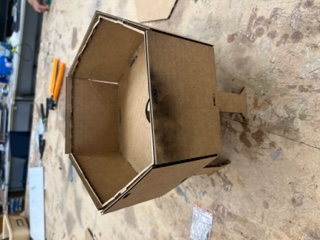
And with this, I reimplimented Kerf and measured some cardboard thickness and prepped it for a test cut. I ran the cut and put together the mock model. It was for the most part designed correctly. The FTDI fit:
The Soil Moisture Sensor fit through when connected:
However the only thing that didn’t fit were the pinouts on the front:
With this I remeasured using calipers and altered the values accordingly. The laser cutters were being used for summer camps so in the mean time I began designing the Water Tank.
Water Tank Design
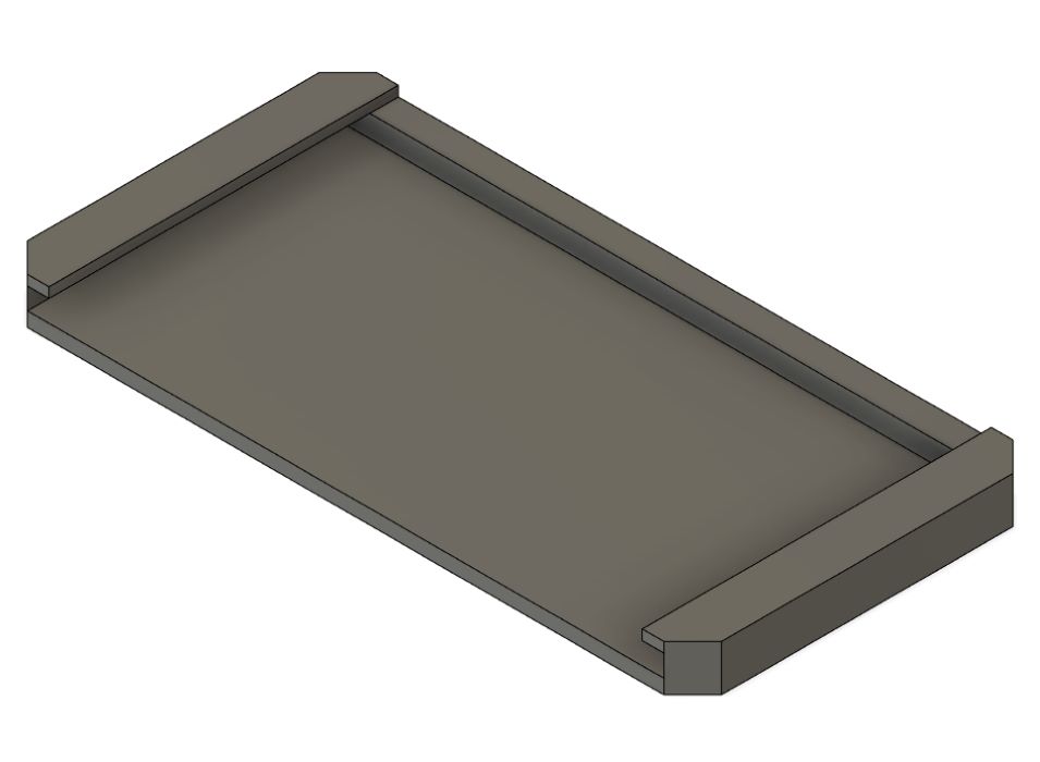
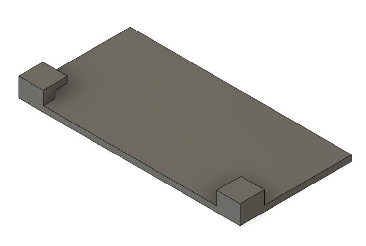
The overall premise is that I wanted about a 1.5 gallon laser cut tank that would stand atop the Main Unit in a way where it could be taken off but also so that it would be secure when actually atop. I began by copying the garden unit file and editing it accordingly. Here are some changes I made:
- Added a hole for the motor in both base plates
- Added holes for the pillars to stand on
And then I went to draw the support beams. I was going to add 4 pillars. I began by designing the initial tabs that fit into:
Cutting the Prior Pieces
I cut the prior panel piece out and the pinouts still didn’t work.
So I went back into Fusion and redrew some dimensions. I then exported this. This cut worked though with wood I’d definitly need to do a bit of sanding.
Cutting in Wood
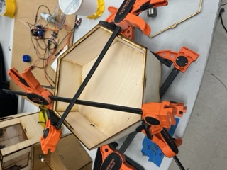
I ended up cutting the design in wood. The tabs were a bit tight so I did some sanding, and the pieces fit press-fitely perfectly.
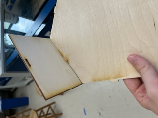
I then used clamps to hold the parts together, to which I glued:
I also glued the lid together:
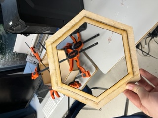
And here is it together:
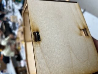
I then fit the headers after a bit of trouble:
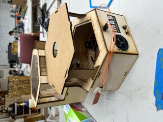
And from here I wanted to lay out on cardboard how my circuit would be shaped. My instructor suggested that I 3D print casings so my PCBs and such could be slid in and out. I began designing those. I landed on this casing for my main PCB:
Then I designed one for the motor driver:
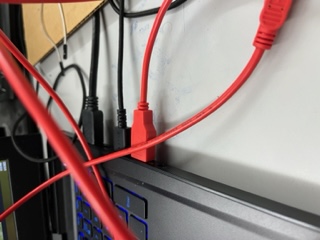
I then went to print these. I also had to drill a hole for the driver power in the front of my unit.
By now my prints had finished. I was able to get the my Main Board secured in the Unit. I glued down the holder to the base plate and was able to slide my PCB right in. This was so my board could be taken out if need be.
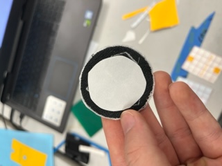
I then went to do the same with the driver, but the pieces snapped pretty quickly. I ended up using velcrow to secure it down, which turned out to be a very nice solution.
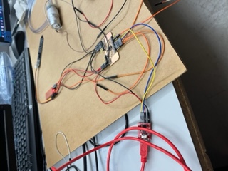
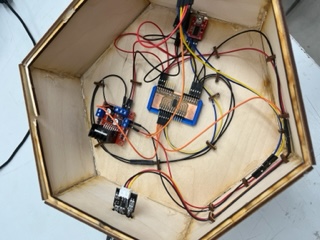
From here, I did most of the remaining wiring/organizing, though some more had to be done tommorow.
I also used tape to hold the jumper wires down in places where I would later want to add a holder of some sort for future wire management!
June 8
Goals:
- Finish wiring
- Finish design/constructing of Water Tank
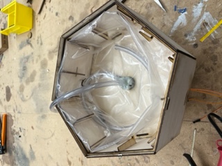
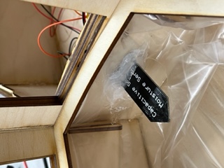
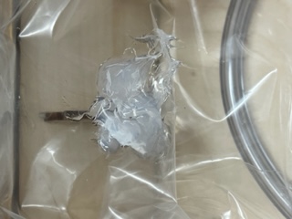
- Insulate Garden Unit
Today was now June 8th and it is 12:10 PM. I spoke with Mr. Dubick about how I should insulate the inside of the units. I already had the idea of using food safe ziplocks and cutting the plastic to use, which he liked, but he also thought I could create a 3D printed piece to lay inside the unit in order to hold said bag. I liked this idea so I hopped into fusion. I used the “measuredPanelSize” parameter from the Garden Unit’s design file as a reference for the inscribed polygon’s initial radius. I then created a smaller hexagon inside this .25 inches smaller. I then gave the object legs so it could stand inside the unit. I used midplanes and the mirror tool to create this feature on all sides with ease.
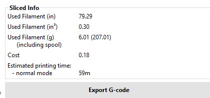
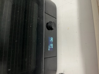
I then also brought the outside of the legs inward a bit so the bag could fit. I then sent it to prusa slicer and began the print. It said it would take 5 hours:
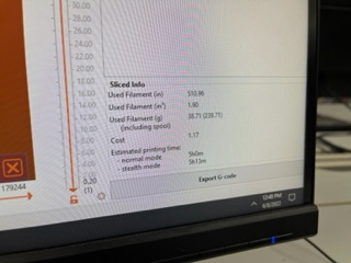
And also I had to use the large printer since it didn’t fit on the small printer bed.
Later after I began the print I realized there must be a better solution. I’d have to wait 10 hours for the parts I needed for them to possible not even work. I realized, like how I did before, that I could just use laser cuttting. I took my 3D file and made it 2D. Since we had summer camps in the lab for another hour, I wouldn’t be able to use the laser cutter quite yet, so I decided to finish up the wiring in my project then do the embroidery/vinyl work. I finished up the wiring:
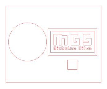
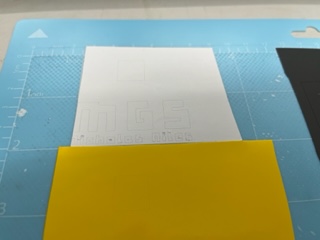
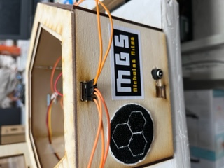
And then went to design a sticker from the text in my Unity Game. I used the nameplate that was already at the bottom of the screen and made a duplicate with some edits to get this:

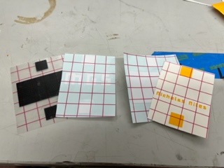
I brought that in:
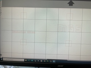
I then screenshotted this and brought it into Silhouette Studio to edit. I then had to change the color scheme of the screenshot because of the trace feature:

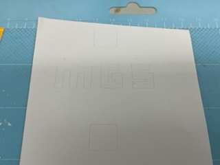
I made a mockup drawing of the entire wall panel so that I could correctly size things. I landed on having a white outline, black background, then white MGS with yellow version of my name under it. I also decided to I’d use squares under each piece to line everything up correctly (and above later on) similar to what I did in Week 2 to make my Fusion sticker. I ended up with this:
And finished with this:
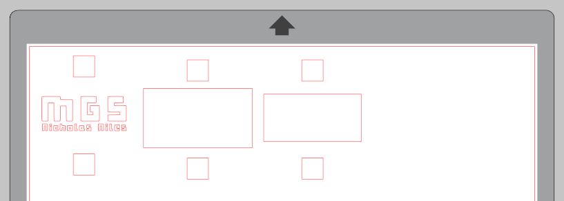
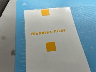
I layed out a cutmap with the correct vinyl colors & placements:
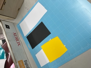
Loaded that, and ran the cut. I then used transfer tape on the sucsesful pieces:
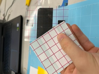
However my name/MGS came out wrong, somehow it was shifted compared to what the app was telling me.
So I went back into Sihlouette and seperated these two pieces:
Then loaded the cutmap and cut them with sucsess:
I then also loaded these onto transfer tape:
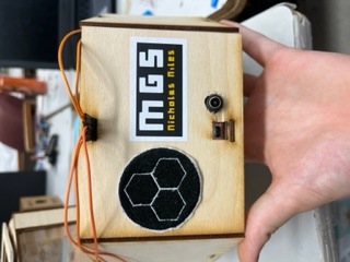
I then used Nitto tape to secure my emblem to my unit:
And from here I applied the rest of the sticker:
Water Tank Test Cuts
I decided now to work on my Water Tank. I used my Fusion files and exported them as .dxf to be worked on then cut from Corel. I cut the files that I had already ready.
And I began by assembling the base ONLY press fit:
Here is how it will eventually sit on top of the electronics unit:
However one error was already apparent: I used the diameter of the pump as the radius of the circle in fusion, so the hole was too big:
I then press fit the panels into the walling:
And then due to the britleness of cardboard I began using glue and put in the inner/upper hexagon piece to hold the walling in place:
I then glued the lid pieces together:
I then tested to see if the pipe could fit into the hole on the lid, which it did well:
One final error I noticed is that I accidently left the tabs on the lid from the Garden Unit design:
So here is what I needed to fix:
- Pump hole size
- Remvoe tabs on lid
- Remove the second base plate piece
So I made these changes and cut the pump plate design only to test the fit and it now was too small. I then remeasured and recut with sucsess:
Cutting in Wood
I updated my parameters to the correct thickness. I exported he dxf, sent it to corel, removed construction lines, and began the cut. I got this:
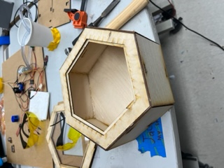
And I constructed using only press fit:
And it came out like this:
However I realized I missed the hole for the water level sensor so I ended up lasering it in low down on the front. I then from here cut the wooden pieces and acrylic pieces needed to make the remaining required lids and I got this:
From here I had these remaining things:
- Create insulation holder for units
- Plant strawberries
- Resin print intersections
- Create plugs for additional holes (Mold/Cast?)
Insulation Holders
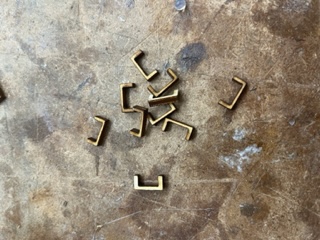
I had a few ideas on how I could go about creating holders, as I previously mentioned I had begun to 3D print a concept, but ultimately nothing stuck. I spoke with fellow fab student Alaric Pan who had the genius solution/idea of creating some kind of hook to hold the plastic in place. I took this idea and ran with it. I hand drew without concern for dimension or parameters (it was very late) a hook design in fusion. I then laser cut said design which looked like this:
Also important to note is that while it was hand drawn I did so within one of the panels to get an idea of its size. I then glued these into the inside panels of the water tank and hooked the bag to these hooks
And this would do for now. Now, it was time to impliment the same for the garden unit. I put hooks in each vertex of the inside:
Then, in fusion, I designed a hexagonal panel (yes, more hexagons) which would lay atop the hooks but within the garden unit. I cut this out, did some sanding, and it worked strikingly well!
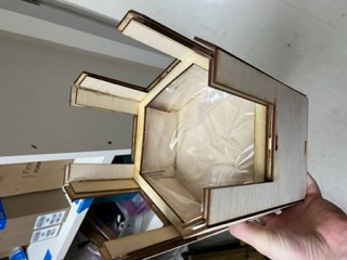
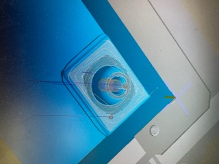
I then cut a hole using a box cutter for the soil moisture sensor. I spoke with Teddy Warner, a previous fab student at our lab, who had done a water based project the prior year, about how I should seal holes in the bags were pipes/sensors were in place. He told me he used silicone to do so, and he also told me to make sure to use 100% plant safe silicone. He also said he could bring me some in tommorow, which I was very greatful about. More about this is documented below in the “June 9th” section. To continue on, however, here is an image of the soil moisture sensor going through the insulation into the unit:
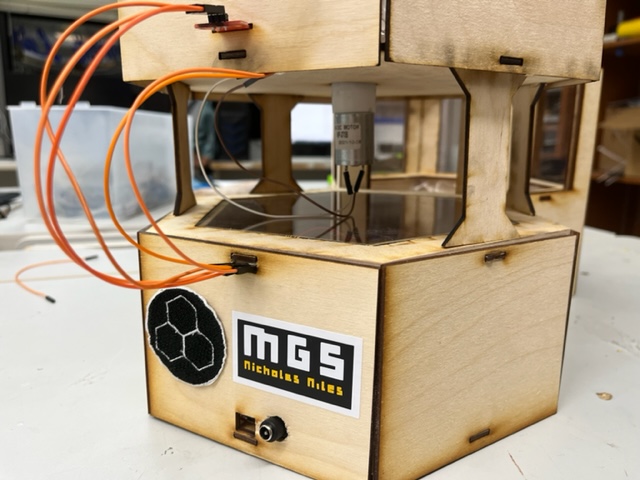
And from there took some hero shots.
Hero Shots for the Night
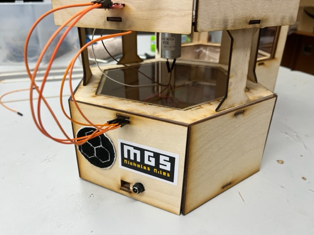

And with that, I am here documenting at 2:13 AM after a 14 ish hour session in the lab, but I am basically done with my project entirely with around 6 or 7 days to spare, so over these days, I will impliment as many weeks as possible.
June 9th
Goals:
- Seal remaining pieces with Silicone
- Plant strawberries
- Test electronics/serial interaction
- GET VIDEOS!!!
- Be done?!
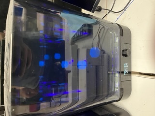
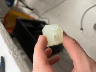
I got to the lab at around 12:15 PM. I got the silicone sealent that Teddy had brought me, but I wanted to ask a few quesions befor using it, and Teddy was in the middle of something so I was going to wait until he was done. In the mean time, I decided to resin print the pipe junctions, I was going to need 2 of them. I pulled my file up on a computer with the program PreForm and sent it to one of our resin printers.
And sent it to the machine:
Now I began using the Silicone to seal my tank and such. I prepped the Silicone and put it into the gun. I used it to seal all of the holes in my design:
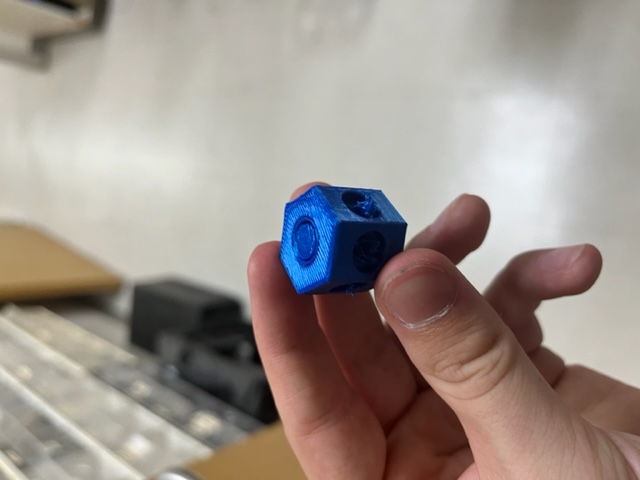
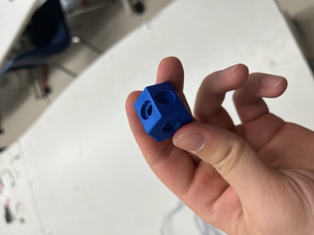
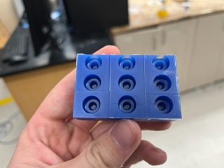
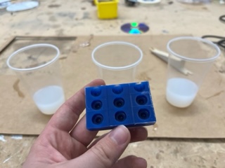
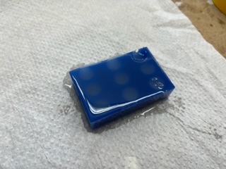
Making Rubber Stoppers
The next piece would be making a mold to cast rubber stoppers. All I did was make a copy of my pipe intersection and turn that hole into a mold:
From here I shrunk it down to more isolate the single hole:
I then realied I needed to flip the object to create the toolpath and also once I did it made the toolpath mill down the sides so I made it a square:
Then, following my Molding & Casting documentation and from there made my toolpaths:
And heres how it came out:
From here I exported my files to the Bantam. I loaded my wax block:
And loaded my mills:
And it turned out like this:
I then got out the Dragon Skin cast:
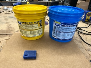
And poured it. I now had to wait quite a few hours:
Resing Printing
Once my Resin Print finished it looked like this:
So I moved the print base to the alcohal pool:
And started it:
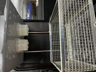
I then took them off and took off as many supports as possible:
I then placed these into the curing machine:
And they came out very well:
And the piping fit in well. By now I went back to check on my dragon skin:
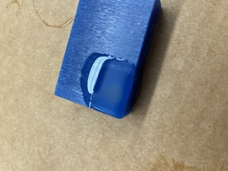
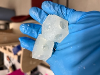
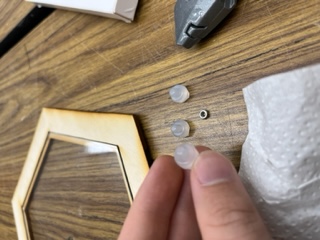
And it came out well. I did some cutting and here is how the plug came out:
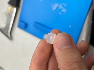
And it fit well into the junction:
So now I went to the milling machine and milled an additional 8 mold spots onto the wax block so I could mass produce plugs overnight. I loaded the wax block:
And loaded each milling file tediously:
And milled:
While I had been waiting for it to mill, I also checked in on my silicone. It had dried very well. I went to the gardening unit, and using a box cutter, I cut a slit for the soil moisture sensor to slide into. It worked well:
Going back to my mills, I vaccumed and this was the final product:
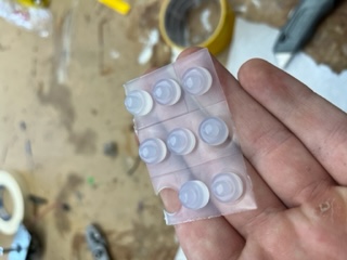
I then prepped the dragon skin once more:
And I poured the molds and stored them to harden overnight.
June 10th
Goals:
- Retrieve and process remaining casts
- Construct simple piping
- Plant some plants!
- Get tons of videos and pictures of functionality
- FINALLY DONE!
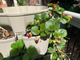
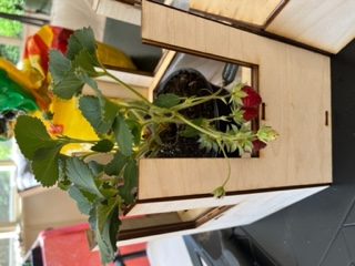
For once, I started off the day at home. Me and my mom together were going to transplant some strawberries from our backyard garden into my garden. We first went outside to pick the best strawberry plant:

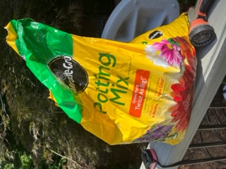
And also grabbed some soil:
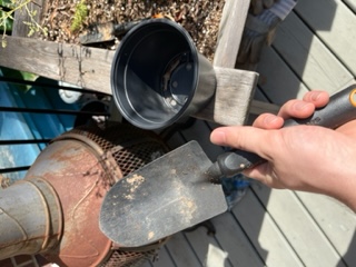
And a shovel/plastic pot:
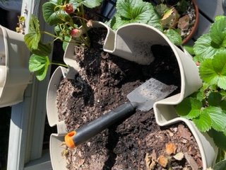
I then dug up the best plant:
And moved it into the plastic pot:
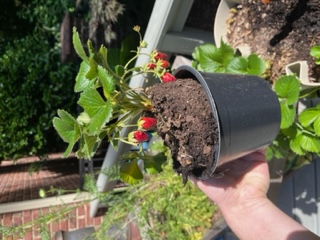
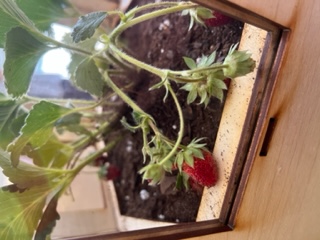
It fit well into the garden:
So I then transfered it and some additional soil:
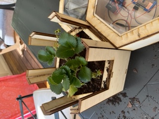
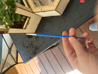
I then used a paintbrush to clean off extra dirt:
And I put the windows back in:
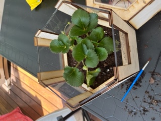
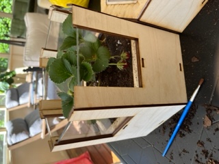
And it came out like this:
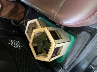
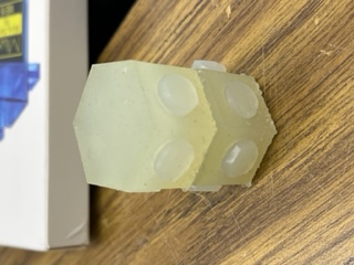
And I used a small green foam to carry my pieces around:
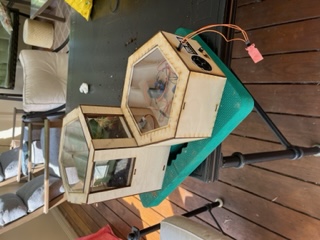
This is how I transported them to the lab:
Once I got to the lab, I got my overnight casts from the shelf.
And I took them out:
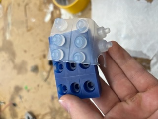
I did some cutting and processing:
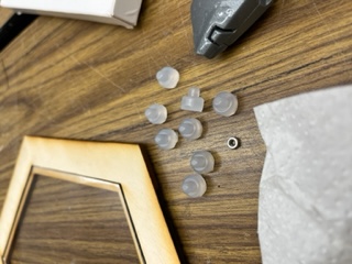
Then I used them to plug un-needed waterways in my junction:
I then realized I hadn’t used the silicone on the water level sensor’s hole. I put the sensor in and sealed the area around it.
Now I was simply waiting for silicone to dry. I thought that I may as well further upgrade my Unity program, try to optimize the code and such.
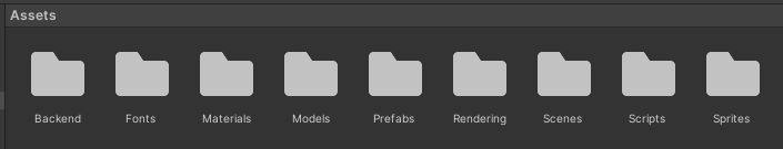
Further Development in Unity
I first organized all of the project files into folders. It looked like this:
I then wanted to prompt the user to select a com port when the program first boots. I first made a new canvas. I added a TextMeshProUGUI to display a title text, then a TextMeshPro drowpdown menu where the user would be able to select the Com port. I then created a script called “SelectionMenu” where I would code all the functionailty.
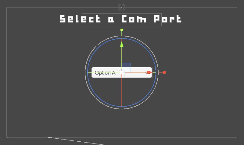
I then stylized the fonts/images to make it fit the style of my project:
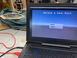
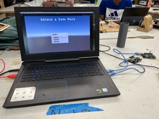
From here I plugged in 2 arduinos on top of my FTDI to test the menu:
I then added a “Continue” button to the bottom of the screen so the user could proceed once a Com port is selected.

June 11
Today I wanted to test my water tank now that all the silicone had dried. I did so and the tank sadly leaked. No damage was caused but it was a setback. I then re-sealed every hole and did a much better job this time, and tommorow morning, I will test it once more and film final videos/pictures. From there, I will develop my slide, video, and update any remaining documentation.
June 12
Today I checked back on my silicone, which seemed to have dried. I poured water into the tank, and it held up perfecty, though I was super scared. I then installed the piping system and tested the pumping capability, which also worked! I then captured videos and photos of my program, entire project, the pumping, and more for my video. The only problem was that some water would leak out of the pipe intersections when pumping, but in the video I avoid showing that. I now began work on my final project video. I wanted my video to be like this:
1st half - skill showcase, manufacturing processes, etc. 3rd fourth - show off each unit individually including their internals/components 4th fourth - show off functionality of project
Also important to show piping system.
For my slide, I wanted it to more reflect the skills it took to make the project than the functionality, though I wanted both to be relevant. I also later today wanted to upload the remaining images on this page that are missing and update all my final project documentation pages.
Later in the day I went to the lab and used the laser cutter to cut small clips for wire management:
And my wire management ended up like this:
June 13th
Today I did some further testing and worked on documentation. I am also finishing up my video:
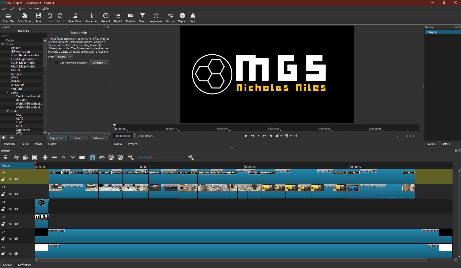
And here is a video of the functioning water systems:
I am also making progress on my slide.
June 14th
I once more continued work on my video and slide. I wrapped up all of this on the day I presented, the 15th, at around 1:30 AM. Close!
June 15th
Today I presented. It was an incredible experience, and I am very happy that Neil liked my project. He said I was the first person to incorporate Unity into final project, which I was happy to hear. Hopefully future students can look at my work or just in general incorporate the program. Now all that is left for me to do is work on Local Evaluation & Global Evaluation work, but atleast the most stressfull part is done!