Week 7: Computer-Controlled Machining¶
This week I designed flat furniture that could be assembled into a 3D chair first using Fusion, then to Corel, then to Aspire, and finally I cut it on our huge Shopbot CNC and assembled it.
Assignment #1: Make (Design, Mill, Assemble) Around the Size of a Meter¶
What I wanted to do for this week was to make a press-fit chair that could actually be used, and press-fit meaning no glue or screws or any additional material would be required to assemble it.
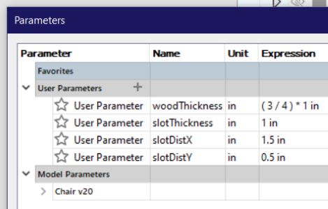
I started by opening Fusion and creating my parameters as I wanted the design to be parametric.
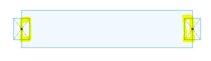
I knew my object would need to be about a meter long but I wanted to change the page size of the Corel file to the same size as the CNC machine bed. I went to go measure the size of the bed. Our Shopbot bed is 8ft by 4ft. I created a sketched box to outline the bed of the CNC in Fusion so I could keep it in mind.
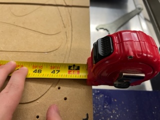
I then went around the room measuring the legs and seats of chairs to get an idea of how I should design mine.
I measured:
Length x Width x Height
16in x 16in x wood thickness for the base of the chair 1.2in x wood thickness x 1.6 feet for the leg of the chair 12in x wood thickness x 12in for the back of the chair (but connected to a set of legs)
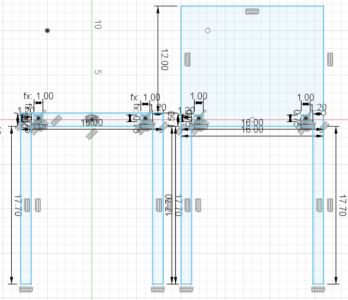
Next I sketched the chair design in Notability to get a general idea, then began sketching the designs using those measurments and parameters in fusion.
And finished by creating the seat base piece.
I also modified and added constriaghts to the edges so that the slots would always be in the same spots even when the other parameters changed and I did so by adding new parameters and lines:
I then actually removed that and redrew each piece except for the first, but on the first I redrew the slots so that the parametric changes worked better. I set the woodThickness parameter to .145 inches which was the measured thickness of the cardboard I would laser cut with to test my design. I then exported it as a dxf and opened it in Corel on the laser cutting computer.
I removed the construction lines and reorganized it.
And then I put a massive piece of cardboard on and cut it.
And then assembled it without glue.
And then I used glue to make sure it could stand on its own just for fun.
But I realized the chair needed crossbars under the legs to prevent the chair legs from sliding apart when you sit on it so I went back into Fusion and designed that.
And then I exported and worked on it and laser cut the new design.
And assembled it.
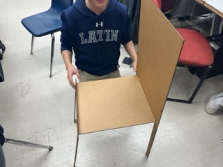
I realized that after building this it would never work, and I rethought the design. I needed to put my joints in a place where the force of sitting would push the joints further together. I decided to once again redesign with a new idea in mind, this time creating the pieces in terms of the back of the chair and seat being their own part and having the legs come up the side and connect everything together. I went to design it.
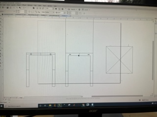
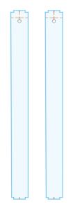
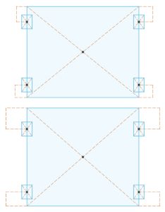
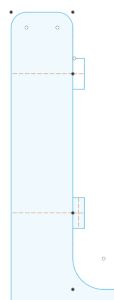
I redesigned what would be the 2 side pieces.
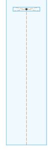
And then the seat and backing.
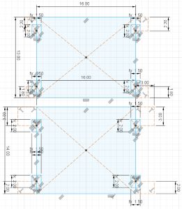
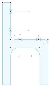
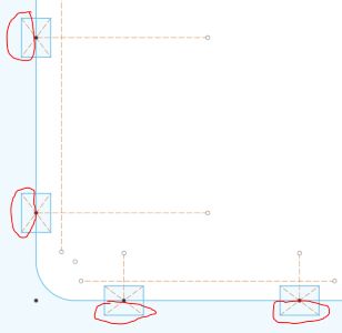
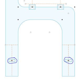
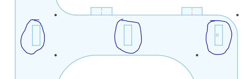
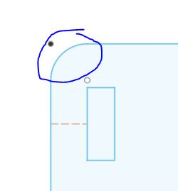
When exporting I will need to prune a lot of construction lines and some main lines such as the inside of the boxes on the chair’s sides:
(AKA delete these highlighted and circled lines)
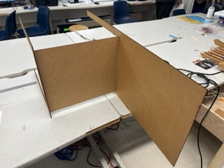
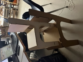
I then took it to corel and laser cut it and assembled it without glue and then with glue.
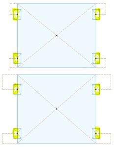
I realized I could improve it by adding support bars on the lower area of the legs, so I did that. Also you’ll notice in the pictures the tabs are too large, and that is because I set the parameter for materialThickness to .75 inches instead of .145 inches by accident. Aside from that, I added the crossbars into my design.
Note the highlights are the removed parts.
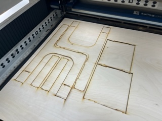
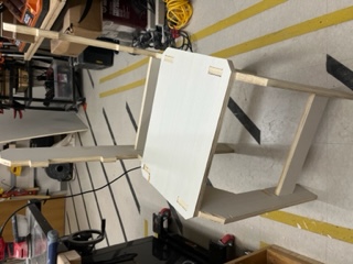
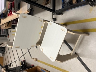
I cut this one out in wood at a 1:2 scale.
And I realized something, that the parametric tabs on my chair piece were not constrained so changing the parameters for the wood thickness shifted my tabs so on the cut I had to use pliers to cut off a piece to make it fit. Knowing that I modified the sketch in fusion to have those missing constraints. Next I wanted to solidify my desgin more by having the seat and back extend over the holes so that the tabs would fit into a hole rather than an open slot. You’ll see what I mean with a few pictures below when I finish it.
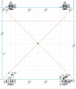
I then added the wood going over/around the tabs of the chair for more security and I also added rounded edges to the seat and back, as well as adding more supports under the chair.
I also laser cut this out in wood.
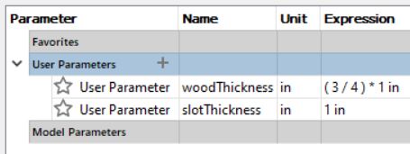
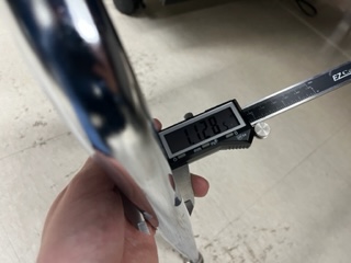
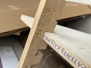
And then knowing it worked I ended up moving my wooden crossbars upward so that they could support the seat more. I then fixed up the constraints a bit more. I went to our wood storage and claimed a piece of .75 inch thick wood which I would use on the ShopBot we have.
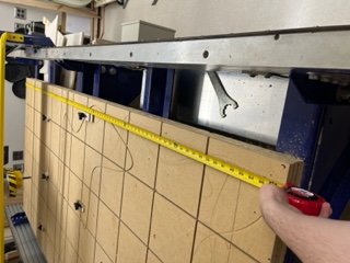
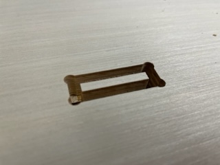
I then used our already cut wood measuring tool to measure the EXACT thickness that would create tight press-fit joints.
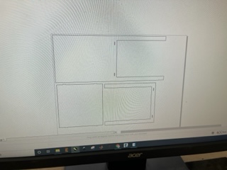
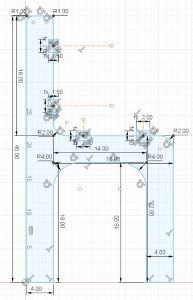
I then set those parameters to my fusion design and exported the dxf. I worked on it in Corel Draw to add all the parts I need and to scale/remove construction lines. Here is my final design before I worked on it in Aspire:
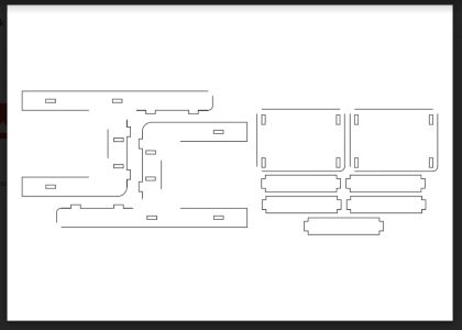
Note that the missing curves are a visual bug in google drive.
Preparing it for the ShopBot¶
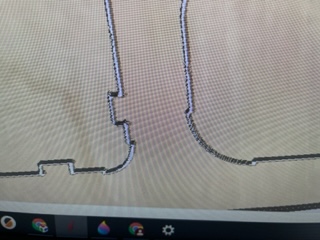
I began by opening my dxf from corel in aspire. I created the first profile and on the preview I noticed I the curved edges were becoming indented and expanded at certain points, something I didn’t want.
After some troubleshooting in Corel, I realized I could redraw the curves in Corel and then export it as a DXF and it would in fact work in Aspire. I then did this with all the curves in my design and continued my work in aspire.
I then realized this didn’t work. After much more trobleshooting, I realized the reason it wasn’t working was because the shapes in Corel weren’t actually closed and the lines were techinally not connected. I redrew the shapes of my chair in a different layer and at the same time to reduce complexity I removed the curves. After doing so I brought it back into Aspire.
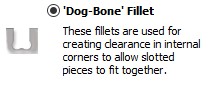
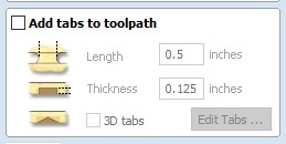
While in aspire I set all the toolpaths up correctly, added dogbones, added tabs, and made sure to configure all the CNC and bit settings correctly.
In regards to toolpaths, aspire has a few.
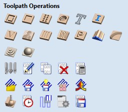
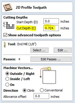
For my chair, I used a profile toolpath for all of my cuts. This meant the machine would cut all the way through the material along a line or edge, so, in this case, all the lines on the chair drawing. A profile has additional settings, such as which side of the line to cut on. It can cut on the middle, the outside, or the inside.
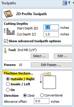
For the outer edges of my chair, to keep the dimensions correct, I used the outside profile cut. For the innter tab hole cutouts, I did the inner setting to ensure the size would be kept correct.
Another major part of creating the toolpaths was setting up the amount of passes. When setting up passes, you can reduce the amount of passes until the depth between the passes is greater than the size of your bit.
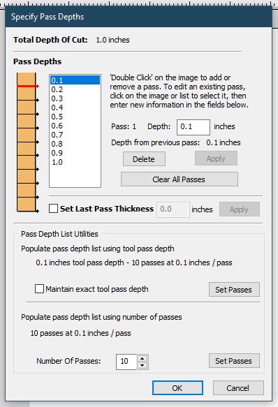
These below were my settings for an 1/8 inch bit:

Lastly I set my cut depth to the material’s thickness:
I then brought it over to Aspire on the ShopBot computer. I followed this workflow from our fablab to prepare the machine to cut:
Shopbot Machine¶
Put on eye and ear protection
Close the doors
Check to see that the machine has been warmed up
Check to see bit is not loose
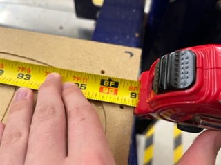
Measure the thickness of the material that you plan to cut.
Raise the Z-axis so the bit won’t drag on the table (no higher than 4 inches)
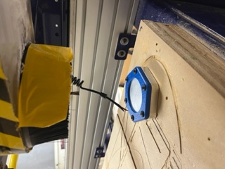
Use the proximity switch to set Calibrate. (C3 keyboard command)
Calibrate Z AXIS on the table. (C2 keyboard command)
Raise Z AXIS 4 inches using the JZ 4 command
Attach material to the table using screws
Raise Z AXIS 4 inches using the JZ 4 command
Set new X and Y Origins for your design
Raise the Z-axis so the bit won’t drag on the table
Using keyboard jog to the appropriate X and Y location. (J2 X,Y)
Using keyboard to zero the appropriate X and Y Location. (Z2)
You set origin.
Select Cut¶
Start up Aspire and VCarve software
Open your file
Select objects you wish to cut
Select Toolpath
Pin Toolpath
Click on material setup
Check Z - zero is on the bed, NOT the board
Enter the thickness of the material *
Model position material should be the same thickness as the material.
Click OK.
Go to TOOL PATH OPERATIONS
Select 2D Profile Toolpath
Under cutting depth, select the cut depth of the material (CLS tools).
Select the proper tool -CLS down bit ¼
Click add tabs and add tabs
Hit CALCULATE.
Preview toolpath
Click on CLOSE
Select SAVE TOOL PATH and save the file in a shopbot format
Start ShopBot Command Console
Conduct air cut
Select FILE-LOAD
Load the appropriate file
We Select 1 3-D offset
Press ENTER
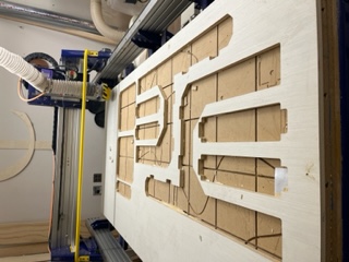
I first brought my material in from the hallway and loaded it on the bed.
And then I screwed it down on all the edges. It is important to note that this was my choice of fixturing the board to the machine, using screws is preferable for larger pieces of wood where as with smaller pieces you can use clamps and many other methods.
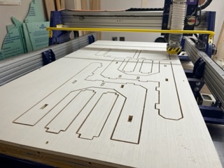
As in the workflow, I then after a lot of setup did a aircut, which is essentially the same cut you would run except high off the material. We do this to make sure the file loaded correctly and that the final cut would be correct, and also to make sure the tabs are properly cutting. After running the aircut, I started the real thing, and began by cutting the tabs out.
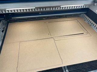
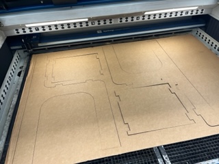
Then I cut my actual outside profiles after running an air cut.
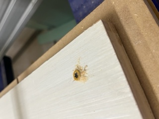
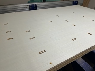
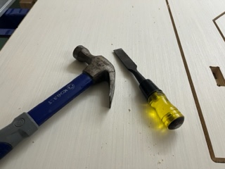
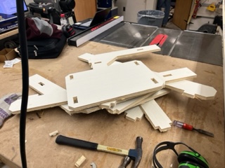
After this I vacuumed up and hopped on top of the CNC bed with a hammer and chisel. I went through each tab I had added in Aspire and chopped it out. One problem I had when removing my parts is that the machine didn’t cut all the way through on a lot of the middle areas, this resulted in a lot more work and effort to remove some parts but in the end they all came out in tact and okay.
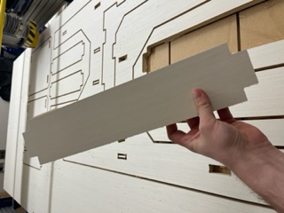
Post Procsessing¶
I then went and did a lot of work after the cut to clean up edges and put the chair together. I began by band sanding and hand sanding the rough edges of the cut.
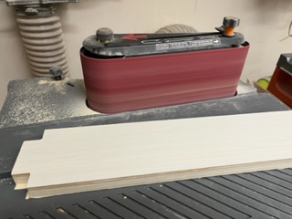
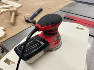
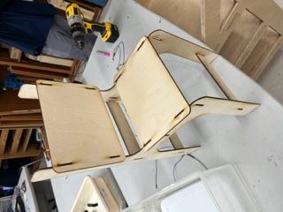
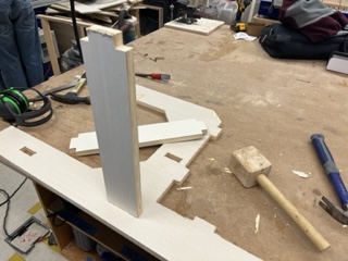
This smoothed out the rough edges. I then started the actually assemble the chair, which was super exctiting. I began by placing one piece on it’s side, then hammering in with a wooden mallet the crossbars for my chair.
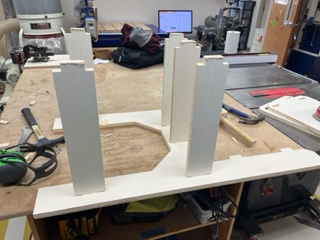
Next I hammered in the other leg/side into the chair. This part was rather difficult as it all had to line up but it worked out.
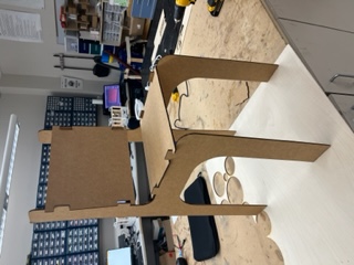
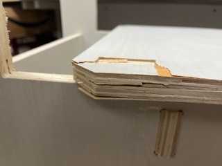
The chair was standing! I was very excited. I then went to hammer the seat in. This took the most effort by far, and it was a super tight fit. I ended up getting it in with some trouble. Because the fit was so tight I ended up cracking one of the corners a bit due to the force of the mallet and the tension. It was barely noticable and I planned on painting it anyways so it was ok.
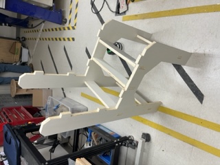
Then finnally I layed it on it’s side and hammered the back into it.
And with that, my chair was complete!!! In fact, I am currently writing this documentation while sitting in the chair.
Dowloads¶
§ Assignment 2: Group Work (Test Runout, Alignment, Speeds, Feeds, Materials, and Toolpaths for your Machine) §¶
All group work is documented on your group site, found here.
For the group work, I contributed by going through the Speeds and Feeds datasheet for our machine and doing a long writeup on the website for it.
Week Summary¶
Overall this week was super fun but very stressful at times. I found in the end it was an amazing week and I learned a ton, I got comftorable with the ShopBot CNC, general woodworking, Aspire, and even learned tons more about constraints in Fusion and shapes in Corel. I ran into many challanges such as the messed up curves, not cutting all the through, cracked wood, all of which I documented about, but from these things I learned a lot which I can apply in later weeks, and I am overall super happy about my chair, the outcome, and the week as a whole.