Week 6: Electronic Design¶
This week I learned a ton about electricity, current, resistance, and voltage. I learned to design custom PCBs in KiCad and even though the week’s goal was to only design our own board and add an LED I also learned to write more complex code with inputs and outputs to create my own board which I milled, soldered, and coded to turn on a light when a button input is detected.
Assignment #1: Replicate and Custom Design an Echo Board (With LED and Button)¶
I started by opening KiCad and creating a new project. I first worked on importing and setting up the Fab library of footprints/symbols. I downloaded the library from the repository here. I followed the steps in the read me and continued.
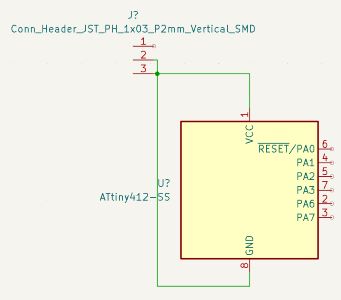
I opened the schematic menu in KiCad then and began designing my board. I started by placing the ATTiny 412 and a three pin header onto the schematic.
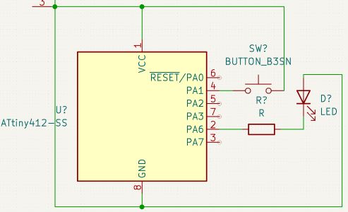
My goal was to detect button input, and seperately output to turn an LED on. Knowing this I went straight to adding the LED and button and wiring it correctly schematically to the correct pins of the chip using this example image on the website of a previous fab student William Zhou. I added these parts and wired them.
I used PA6 of the chip for the LED and PA1 for the button input, these equating to digital 0 and 2.
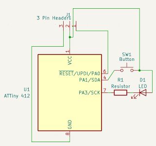
I reorganized the wiring.

And I changed the naming of the symbols on my board and went into the symbol editor to hide unneeded chip outputs and connections to run the electronics check.
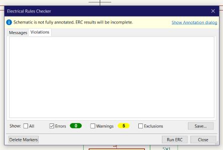
I then ran the electronics check with sucsess AFTER adding the power flags to act as my power and ground.
Now it was time to open the PCB editor. When I went to import it, I had tons of errors. It said it couldn’t load the footprint for the Fab Library parts.
After tons of trouble shooting, trying to run through the read me process 10 times, I found the error. In my footprint library manager, where I added the fab.pretty folder, I had to rename the nickname to “Fab” to fix the errors.
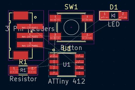
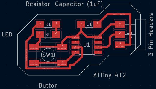
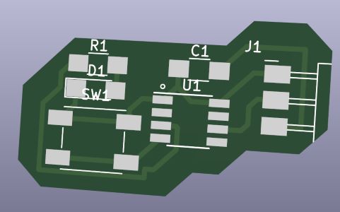
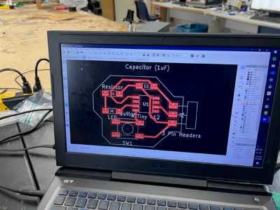
From here I layed out my PCB parts and began manually routing.
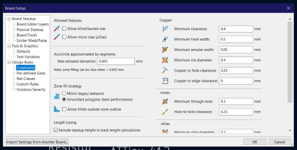
I also went File>Board Setup>Constraints and set Minimum Clearence to 0.4mm and Minimum Track Width to 0.5mm.
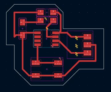
Now I routed starting with this base clump of components:
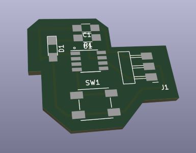
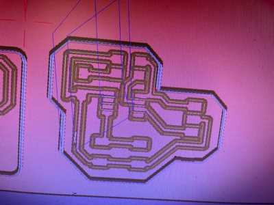
And I organized and drew the outline of the board to get this:
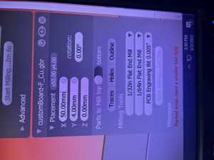
Now I exported my files as gerbers. I went to my milling machine and imported the file.
And set the settings up for the tool.
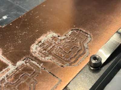
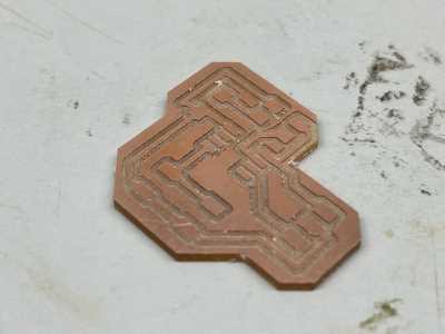
I followed the workflow created two weeks ago and began milling. Here is the final product:
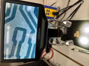
I then went through the process of Post Processing on the board. I washed it and examined the traces under a microscope to check for any small shards of copper bridging and cleared those out.
Finally it was ready to be soldered.
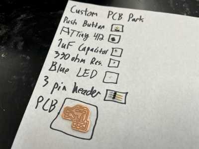
I gathered my components on a sheet of paper as usual.
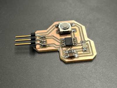
I then soldered all of them on.
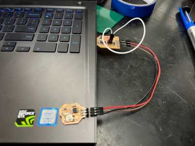
And I got out my programmer and hooked up the UPDI pin to my new board and I opened the arduino IDE. I used this image to hook my old programmer up to my new board correctly.
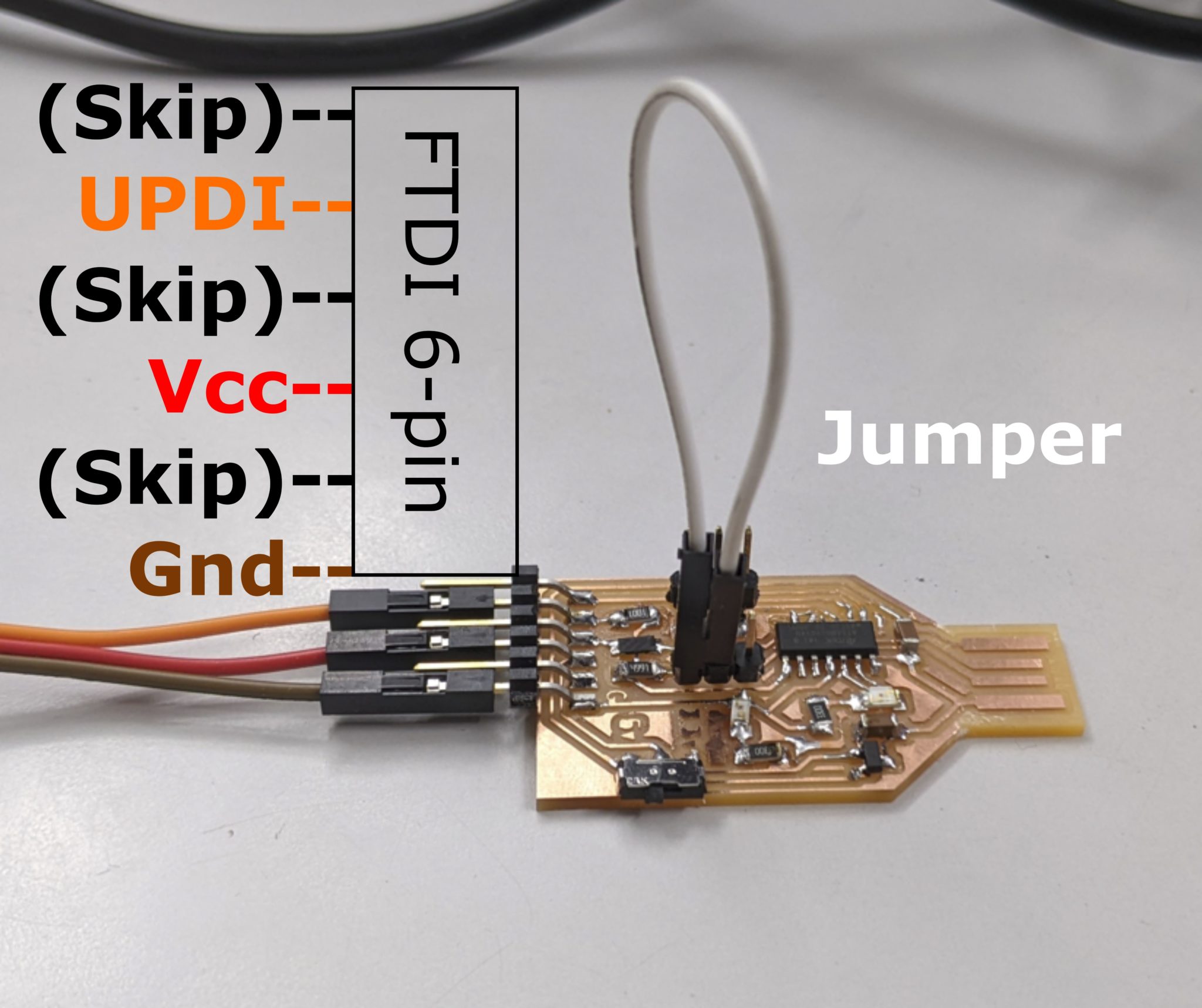
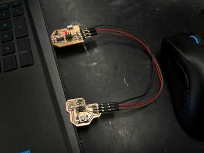
I began coding my arduino program that would manage the button input and LED output and then I set up the tool settings in the Arduino IDE. Finally, I sent my code through the programmer and into my new chip.
void setup() {
  Serial.begin(9600);
  pinMode(2, INPUT_PULLUP);
  pinMode(0, OUTPUT);
}

void loop() {
  int sensorVal = digitalRead(2);
  Serial.println(sensorVal);
  if (sensorVal == HIGH) {
    digitalWrite(0, LOW);
  } else {
    digitalWrite(0, HIGH);
  }
}
This code didn’t work. I modified it so that the light would simply turn on. The light did in fact turn on on the board.
However I couldn’t get the button to work. I went back to my schematic and analyzed it for issues.
Big Oversight¶
I found the issue, the button went from my input pin on the chip back to VCC, so no ground was ever established or connected to the button so input couldn’t be detected and it would only read the button as LOW. This meant I had to redraw my schematic, redraw my PCB layout, remill, etc., essentially redoing the entire process over.
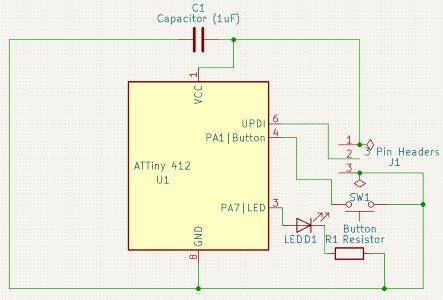
To do so, I began by deleting all the wires and completely rerouting my schematic. It turned out like this:
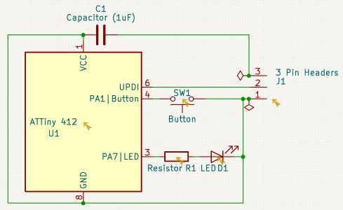
Note that I changed the pinouts I used on the ATTiny 412. I now had my LED output set to PA7 or arduino pin number 1. I changed my button input pin to PA1 or arduino pin number 2. I then opened it in the PCB editor and routed my lines.
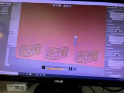
I then exported my gerbers and brought them to the milling machine. I milled them and cleaned them to get my new board, note that I made three:
I then gathered my parts as before and proceeded through the same soldering process.
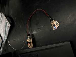
I then hooked it up to my programmer as before.
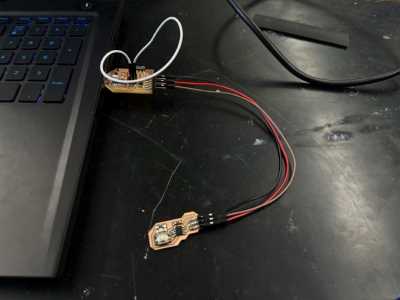
And send the code over with FAILURE. I made another crucial electronic mistake in my design. The VCC went straight to a capicator and had no other route to travel straight out of my pins. While I don’t understand the electronics behind why this doesn’t work quite yet, I do know it doesn’t work. Now it was time to do it all over again.
Third Time¶
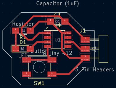
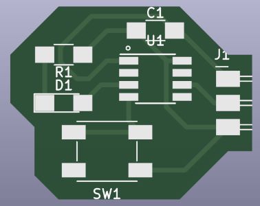
After re-running the entire process with this new design:
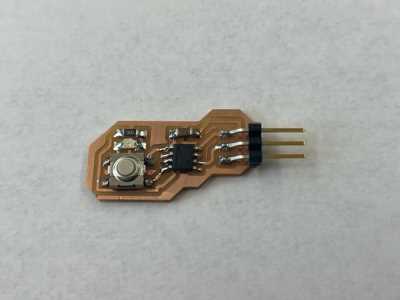
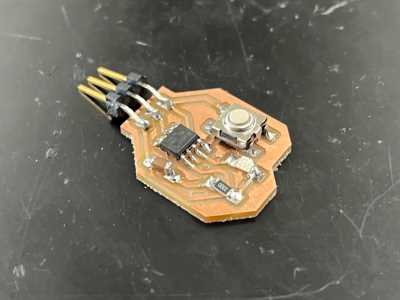
I milled this and processed it and soldered.
And uploaded this code:
void setup() {
  Serial.begin(9600);
  pinMode(2, INPUT_PULLUP);
  pinMode(1, OUTPUT);
}

void loop() {
  int sensorVal = digitalRead(2);
  Serial.println(sensorVal);
  if (sensorVal == HIGH) {
    digitalWrite(1, LOW);
  } else {
    digitalWrite(1, HIGH);
  }
}
With success.
Dowloads¶
My code can be found above.
§ Assignment 2: Group Work (Use the Test Equipment in Your Lab to Observe the Operation of a Microcontroller Circuit board) §¶
All group work is documented on your group site, found here.
Week Summary¶
Overall, this week was very productive in moving my understanding of electricity and electronics forward. I learned of many different components and their applications and this furthered my understanding of electricity greatly. I also learned how to easily design and route my own custom PCB boards, and finally got full comftorable with the milling machine. This was definately the best week so far for my learning in my opinion.