Modular Gardening
Final Project Presentation Material
What is my Project?
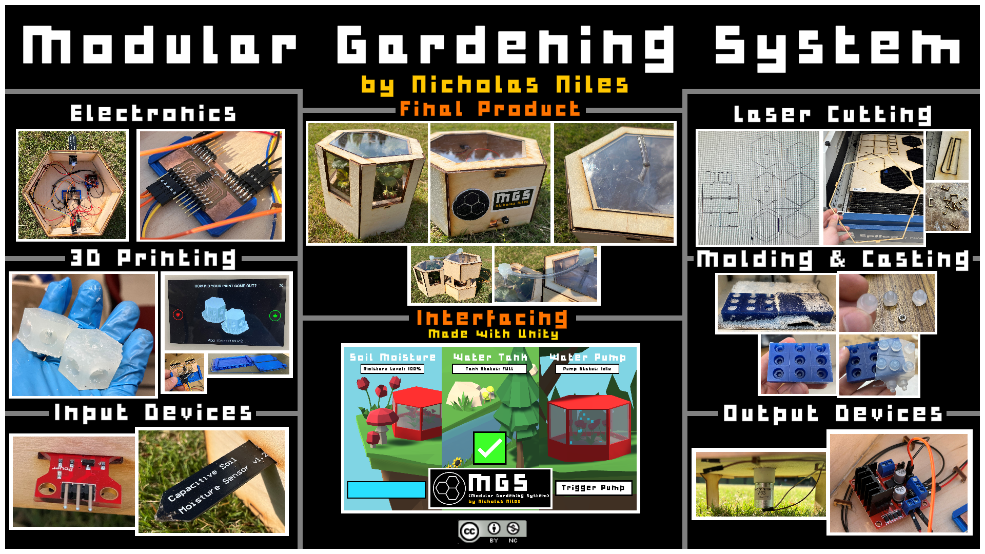
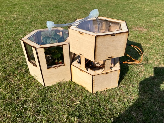
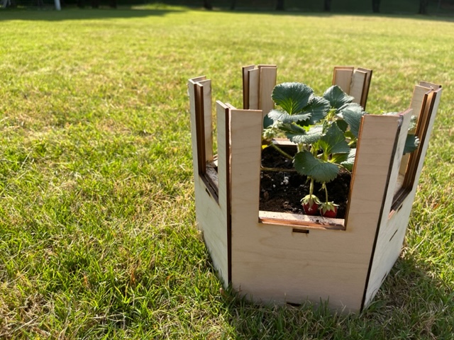
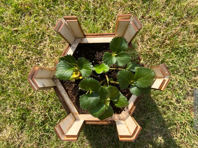
My project are hexagonal gardens that fit to form any shape or size desired by the creator that has one central hexagonal unit which houses the electronics, water, and screen for data and research. The system waters itself based off of sensor data via a relay-controlled DC pump as well as captures/stores data from sensors which can be plotted over time. There are two types of hexagonal “Units” as they are called that make up this project.
File Downloads
Download of all the project’s files right here!
Licensing
This project is licensed under Creative Commons 4.0, good for personal but not permitted for commercial use.

This work is licensed under a Creative Commons Attribution-NonCommercial 4.0 International License.
BOM (Bill of Materials)
This project requires quite a few parts. Below is a table of what parts and how many are needed to produce this project:
| Part Name | Amount Required |
|---|---|
| 1/8 Inch Wood | 3 30x20 sheets |
| 1/8 Inch Plexiglass | 1 30x20 sheet |
| Matt Black Vinyl | 1 sheet |
| Matt White Vinyl | 1 sheet |
| Yellow Vinyl | 1 sheet |
| Black String | 1 spool |
| White String | 1 spool |
| FTDI Breakout Board | x1 |
| L298 Motor Driver | x1 |
| FR1 One-Sided PCB | 1 sheet |
| ATTiny 1614 Chip | x1 |
| 1 uF Capacitor | x1 |
| 8 Pin Horizontal Header | x2 |
| 12 Pin Horizontal Header | x1 |
| DC Pump | x1 |
| Water Level Sensor | x1 |
| Soil Moisture Sensor | x1 |
| 2 Gallon Food-Safe Bag | x2 |
| 100% no-adative Silicon | 1 tube |
| PLA Filiment | 1 spool |
| Resin | 1 gallon |
| Alcohol | 1 gallon |
| Male-to-male jumper wires | 1 package |
| Male-to-female jumper wires | 1 package |
| Female-to-female jumper wires | 1 package |
Final Build
Major Components
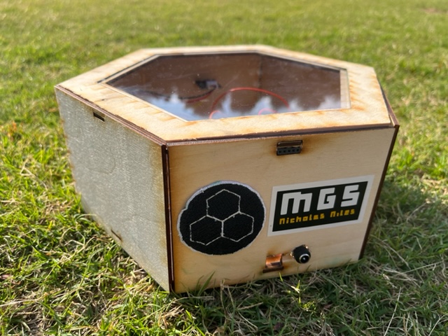
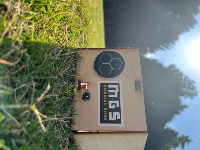
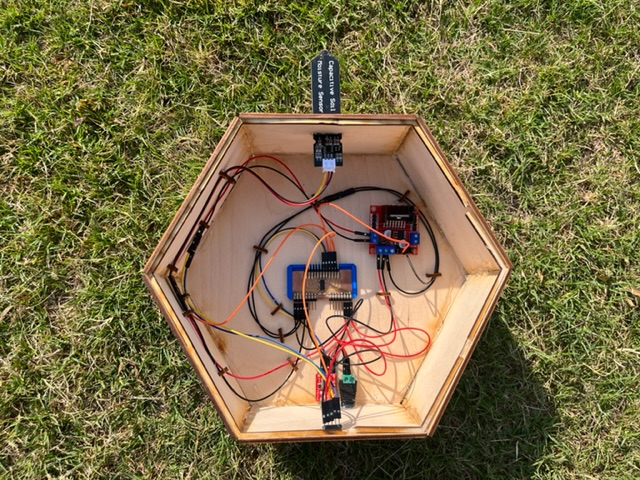
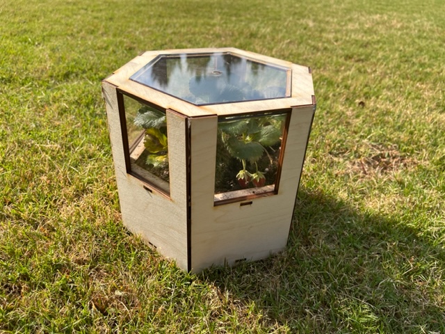
Main Unit
The Main Unit is responsible for all the majority of the electronics and the serial communication between the Attiny 1614 chip and the USB cord.
It includes the following electronics:
All-Purpose PCB
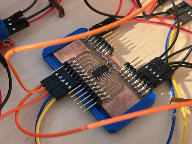
This PCB, designed by myself, allows for 8 VCCs, 8 Grounds, Rx, Tx, UPDI, and 9 additional analog/digital inputs/outputs.
L298 Motor Driver
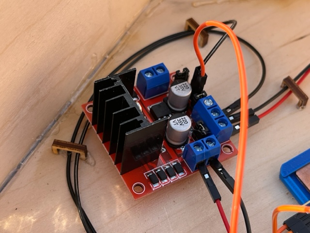
The L298 Motor Driver allows for the toggling of the DC Water Pump. It is needed because the pump pulls too much current compared to the PCB Board.
Soil Moisture Sensor
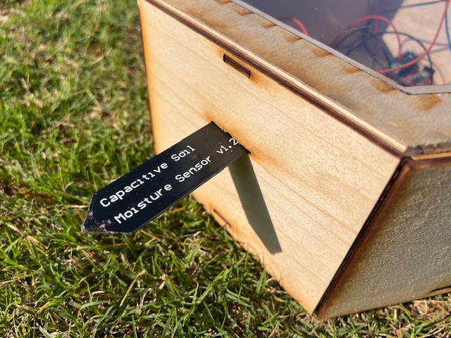
The Soil Moisture Sensor sticking out of the side of this unit plugs into an adjacent Garden Unit, and sensing the moisture of the soil in that adjacent unit and communicates it back to the 1614 chip on the PCB Board I designed.
FTDI Breakout & Power Input
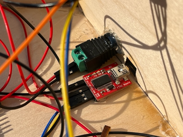
The FTDI Breakout, on the lower right, allows for Serial communication from the PCB Board to any device’s USB port. It also gives power to the system.
The Power Input, on the upper left, is what gives power to the L298 Motor Driver and later the DC Pump.
Additional Features
The Main Unit also has a removable lid for ease of acsess to electronic components:
And additionally strong wire management through lasercut wire holders:
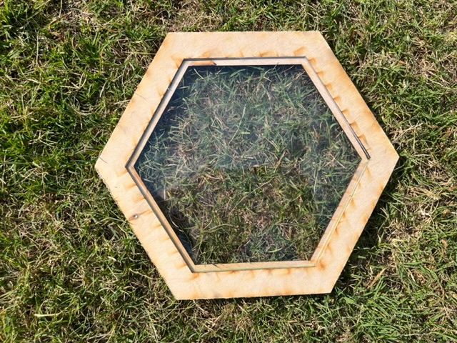
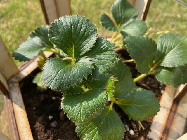
Garden Unit
The Garden Unit is responsible for housing soil and plants to be grown. Certain Garden Units (one in every array) have an additional hole in the side for the Soil Moisture Sensor of the Main Unit. Each Unit is insulated with food-safe plastic and 100% no-addatives plant safe water proof silicone.
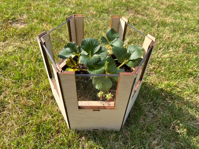
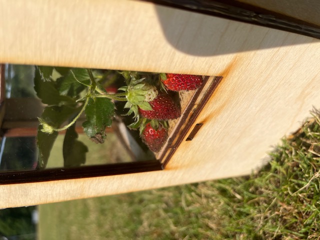
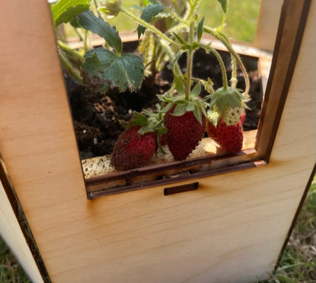
Additional Features
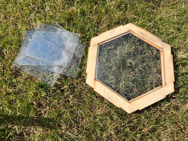
The Lid of the Unit is able to be easily removed, as well as the plexiglass walling that slides into each side for ease of access to the plants/soil.
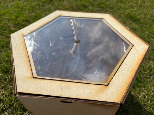
Water Tank
The Water Tank stacks atop the Main Unit. It’s purpose is to hold water as well as to report the status of the tank’s fullness back to the 1614 chip within the Main Unit. It also has a built-in DC pump for the purpose of pumping water from the tank to all Garden Units. The Unit is also insulated by food-safe plastic and also 100% no-addatives silicone.
It includes the following electronics:
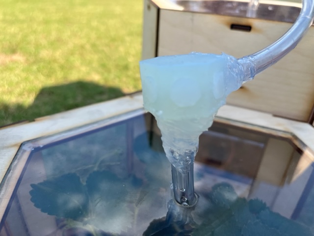
DC Pump
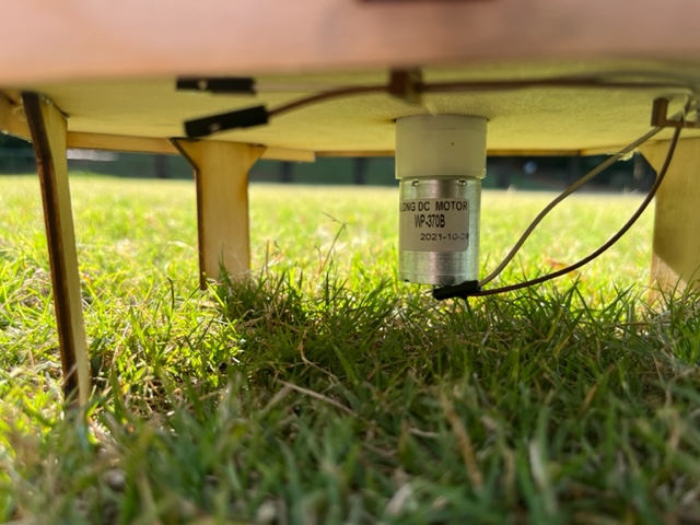
The DC Pump, toggled/controlled via the L298 Motor Driver. It has plastic piping leading from the water of the tank outside. The pump itself has an inlet and an outlet.
Water Level Sensor
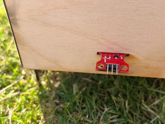
The Water Level Sensor reads the fullness of the tank and reports it back to the Main Unit.
Modular Piping System
What makes this project modular is the fact that no matter how many Garden Units the user needs, as many as are needed can be connected to the Main Unit through the piping system which is designed to allow easy additions which allows water to be piped to every unit in the array easily.
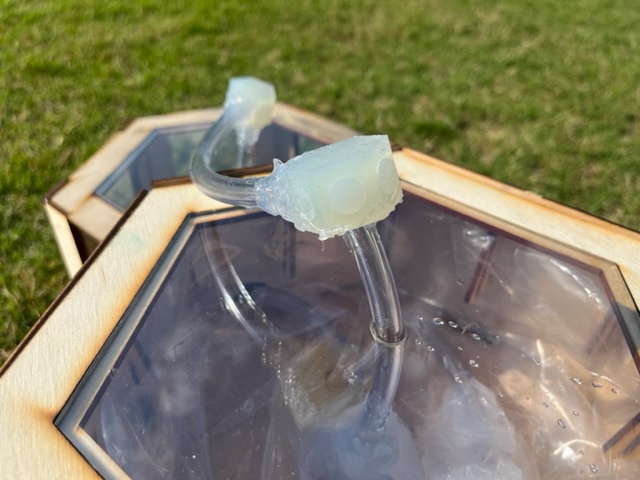
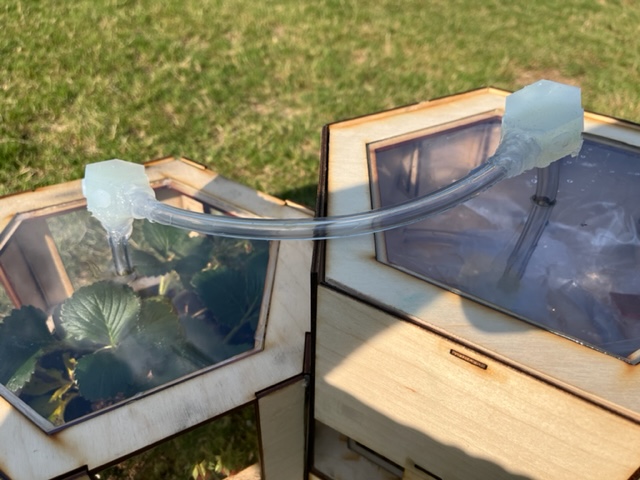
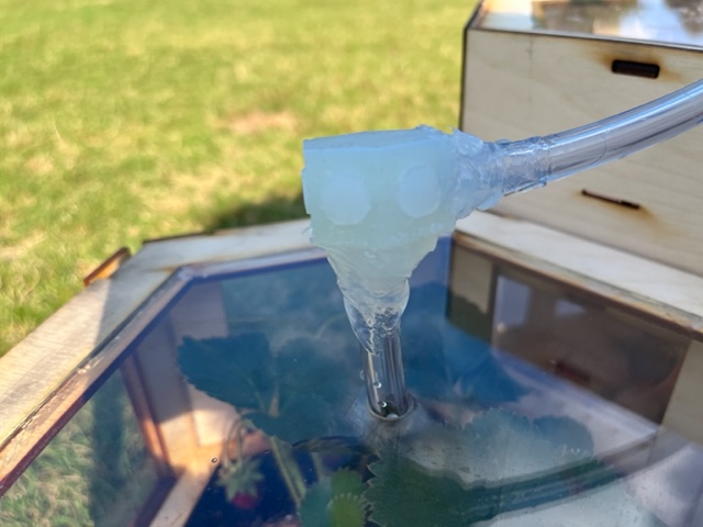
Each pipe intersection has 7 holes, one on the bottom and 6 on each side of the hexagon. This allows for additional units to be attached to the piping system adjacently, or the hole can be plugged with custom molded/casted stoppers that fill the hole and block the water.
Interfacing the Recieved Data
All of the data retrieved from the 2 sensors as well as the pinout status of the only ouput (the pump) is retireved, packed, and sent via Tx to the FTDI Breakout, who then relays that through a USB cable to whatever device (in this case, my laptop) is hosting the interpreting/display program. This program then parses the data, does lots of math, and displays this data on-screen to the user.

The program first prompts you to select which USB port that the device is plugged into, making it versatile for other devices, as opposed to hardcoding my personal COM port which the device has been using, in my case, COM4. From here, the initial display will show:
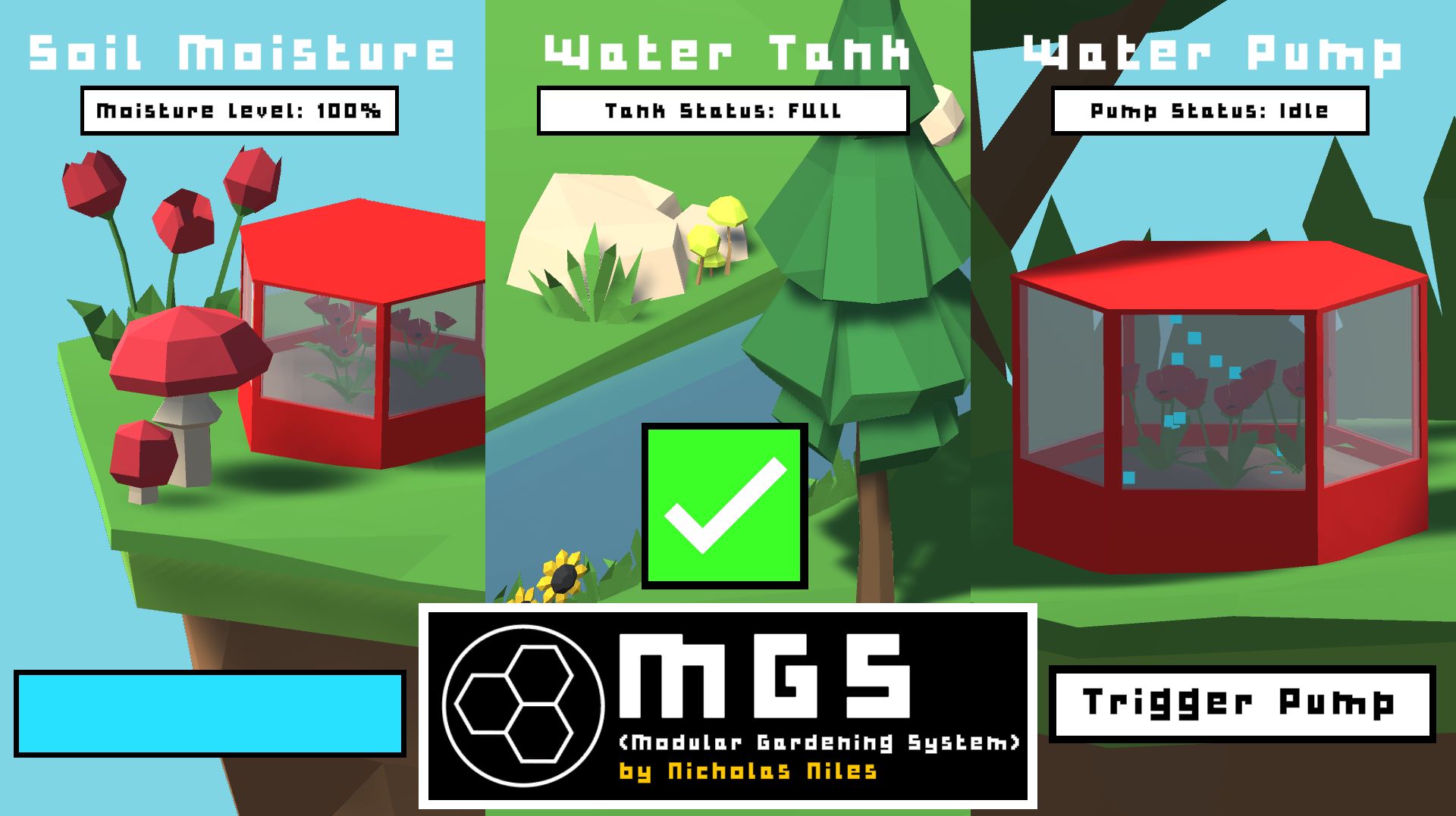
This display has three main sections:
The Soil Moisture Display

This display shows the percentage of how moist the soil is at the top. It is also displayed in a bar at the bottom. If the sensor reads under 10% soil moisture, the pump will automatically turn on.
The display will show a desert scene from 0-20%, and rain/forestry will be shown between 21-100%, with the rain effect in that scene increasing in particle count based on how high that % is.
Water Tank Display

The middle display shows how full the water tank, either full, or empty. It helps let the user know wether they need to refill the tank or not.
If the sensor reads no water, the display will show a desert scene accompanied by a large red x and the text “EMPTY” at the top. If it detects water, than the tank is considerably full, and the display will show forested scene and the text “FULL” at the top.
Water Pump Display
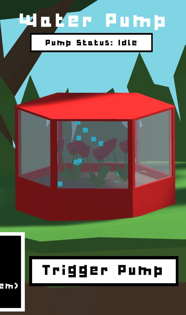
The last display shows wether or not the pump is actively running. If the pump is actively running, the text at the top and the button text will read “PUMPING…” and a particle effect appears in the tank in the program.
If it is not pumping, the text will say “IDLE” as well as the button, and the particle effect disappears.
The Goal of the Project
The goal of the Modular Gardening System is to act as a prototype which could be further developed later on, but for now is to safely grow plants without having to manage them, and also to track information about them thorugh the statistics captured through the sensors.
What skills does my project use that we’ve learned?
Week 1: Principles & Practices | Project Management
- Outlining my Initial Final Project Idea
- Sketches/Planning of Final Project
Week 2: Computer Aided Design
- Design of the Units (3D)
- Design of Acrylic Panels (2D)
- Design of PCB & Schematics
- Design of a Mold for Rubber Stoppers
Week 3: Computer Controlled Cutting
- Laser Cutting Acrylic Panels
- Laser Cutting Entire Shelling/Bodies
- Milling Boards via Milling Machine
- Milling Molds via Milling Machine
- Vinyl Sticker for Logo
Week 4: Electronics Production
- Milling Custom Input/Output Combined Board
Week 5: 3D Scanning & Printing
- Printing Electronics Fixturing/Holders
- Resin Printing Pipe Junctions
Week 6: Electronics Design
- Design of Custom PCB Board for Sensors & Chip
Week 7: Computer Controlled Machining
- Mold Cutting/Drilling via Bantim Mill
Week 8: Embedded Programming
- Programming the Chip on the Custom Milled Board
Week 9: Molding & Casting
- Molding & Casting Rubber Stoppers for Piping
Week 10: Output Devices
- Driver Component Controlled Via ATTiny1614
- DC Motor (Functioning as a Pump) Controlled Via Driver
Week 11: Mechanical Design
- Systems for Moving Water To Different Places
- Systems for Pumping Water
Week 12: Input Devices
- Soil Moisture Sensor Read Via ATTiny1614
- Water Level Sensor Read Via ATTiny1614
Week 13: Networking & Communications
- Communication Via Tx & Rx between Unity (Via Serial USB to Laptop) through FTDI Breakout to a 1614 Chip’s Rx and Tx Lines
Week 14: Interface & Application Programming
- Unity Application to Display Sensor Values & to Log Said Values over Time for Research Purposes
Week 15: Wildcard Week
- Embroidered Logo (Designed & Embroidered Patch to go on the Front of the Master Unit)
Week 16: Applications & Implications
- Project Outlining
Week 17: Invention, Intellectual Property, and Income
- Licensing & Copyright
Week 18 Project Development
- Further Project Outlining
Final Project Questions
What does it do?
- Maintain plants
- Retrieve data from the soil in which the plants sit
- Interpret and display said data to the user
Who’s done what beforehand?
- No one that I know of, this is my own idea, though I wouldn’t doubt something similarly being done before
What did you design?
- Every 3D model, Every 2D laser cut file, Every additional CAD file
- All code
- All electronics work/designing
- Essentially, everything except for the plastic lining, L298 motor driver, and FTDI breakout board
What materials and components were used?
- Wood
- FR1 PCB
- PLA Filiment
- Embroidery Materials
- Electronic Components
- Laptop of any kind
- ATTiny 1614
- L298 Motor Driver
- DC Pump
- Soil Moisture Sensor
- Water Level Sensor
- Capacitors
- Pin Headers
- Jumper Wires
- Acrylic/Plexiglass
Where did they come from?
- Digikey (Electronic Components)
- Lab Provided Materials (Embroidery Materials, PCB, Wood, Sensors)
- My House (Laptop)
How much did they cost?
- All of the materials EXCLUDING the acrylic/plexiglass are under $5-$10 and the overall build is easily under $100
What parts and systems were made?
- Input System
- Output System
- Sensor Interpratation/Math/Display in Unity
- Entire Framework/Construction of Physical Units made Via Laser Cutter/3D Printer
- Pipework System (For Pumping Water)
What processes were used?
- CAD
- Laser Cutting
- 3D Printing
- Molding & Casting
- Interfacing
- Electronics Design (Milling)
- CNCing (Wax Blocks)
- Vinyl Cutting
What questions were answered?
- How power is to be distributed amongst the components/boards correctly from a singular source
- How to read Serial Data into Unity
What worked? What didn’t?
- My sensors and relay worked well which really surprised me, as they were one of the most complicated part
- The initial serial reading program did not at all work for me and gave me weird chars from my serial port
- Using a relay in the end costed too much power with my system so I made the switch to an L298 motor driver
How was it evaluated?
- I evaluated a lot of my issues by doing tons of research on problems I would have, documenting such, and finding workarounds or solutions to any issues I was having.
What are the implications?
- Gardens can be built to any size or shape wanted and additionally this entire concept as a whole can be GREATLY expanded and worked on down the line to potentially network the units and greatly expand the number of sensors and values that can be retrieved
- Plant development/Growth can be researched through the findings of the device (Especially with future expansion)
What Would I Change/Fix In A Second Prototype?
There are many aspects/parts of this creation that I would change and improve if a second prototype were to be made. Here are a list of changes (simplified) which I would look to make:
-
Having a much more sturdier, 100% pressfit, and more basic design for all the units. A lot of them, especially the Garden Unit, had designs which needed a lot of post-processing work after the laser cutter, something which I would look to remove in future versions. I would also want to more-incorporate 3D printing into these units to help with the build quality and sturdiness.
-
I would stain and seal the wood and units much better.
-
I would use a clear plexiglass or plant-safe acrylic for the water tightness in the Water Tank/Garden Unit instead of plastic, as it was very difficult to work with, and incredibly un-needed for the design.
-
Piping imporvements/silicone learnings. I learned lots about silicone, especially that it needs 24 hours to drive as oppose to 12, something that caused many issues. The pipping also needs to be a lot more press fit, and I think built into the design more than it is right now.