Week 3: Computer Controlled Cutting¶
This week I learned to use Parametric Design in Fusion and used it to Laser Cut small toys that fit together using the cardboard’s thickness as a parameter.
§ Assignment 1: Cut Something on the Vinyl Cutting §¶
Using the sticker which I designed during CAD week (Week 2) in Corel Draw, I went to cut the vinyl to make my sticker. Dowloads are listed at the bottom of my Week 2 page.
Using Silhouette Studio¶
For each of the 4 layers, I went through the following process:
1 . Importing the file into Silhouette Studio¶
2 . Then I traced the JPG image to the correct threshhold so that all my lines and edges would appear correctly in Silhouette.¶
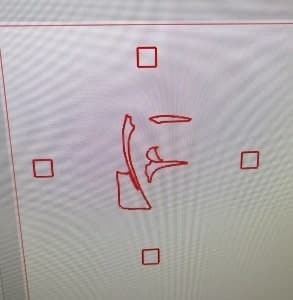
3 . I then scaled the image to the correct 3 x 3 inch size¶
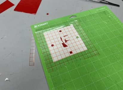
4 . I then put the correct color vinyl on the cutmap and loaded it into the cutter¶
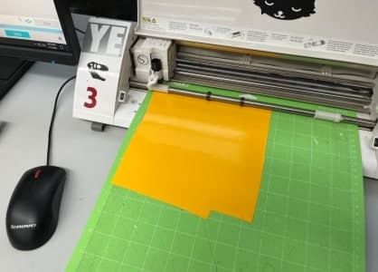
5 . Then I hit the “send” button in Silhouette to send the file to the vinyl cutter to begin the cut¶

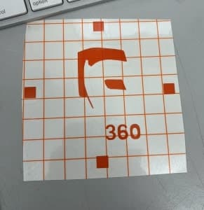
6 . Then I picked out all the excess vinyl that I didn’t need on my sticker using the tools¶
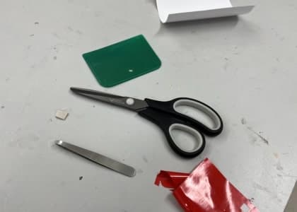
7 . I then used Transfer Tape to put over top of the vinyl sticker to prepare it for placement onto the surface I wanted to put it on¶
![]()
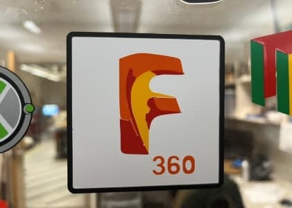
Final Product¶
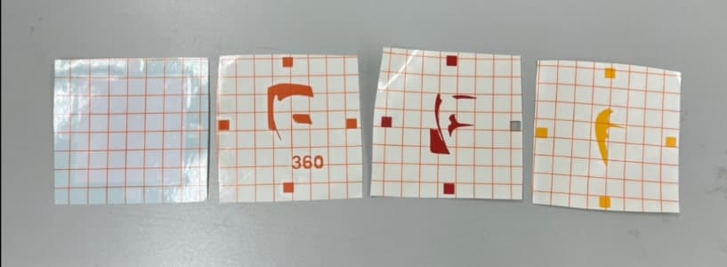
Finished Layers¶
After repeating this process 4 times for each layer, I had all the pieces I needed:
Then, layer by layer, I placed it onto the glass window layer by layer lining up the squares to get this:
§ Assignment 2: Design & Lasercut a Parametric Construction Kit §¶
The idea behind parametric design is that we can sketch objects in Fusion using parameters as our dimensions so that when the entire object is scaled these dimensions maintain the same size and also so that we can easily change the size of one particular feature or multiple features by simply changing the number of the parameter.
My Goal¶
My goal was to create small cardboard pieces that fit together parametrically so that they could be easily modified to fit the thickness of the cardboard I was using to create them. I hoped in the end to have small pieces that could be put together with different shapes to build small creations.
Getting Started¶
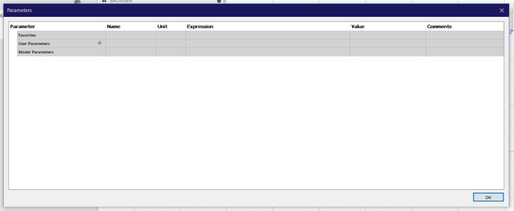
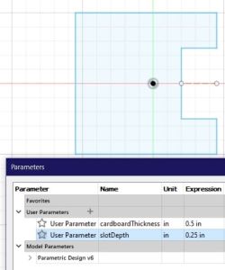
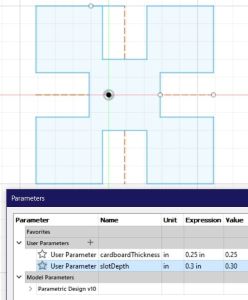
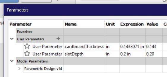
To begin, I opened a new fusion document and opened the “Parameters” menu under modify.
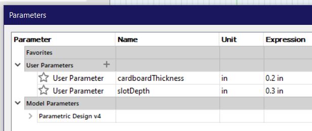
I then added the two parameters I would be using for this project.
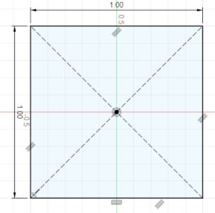
For the first piece, I was going to cut a square. I began by sketching a square:
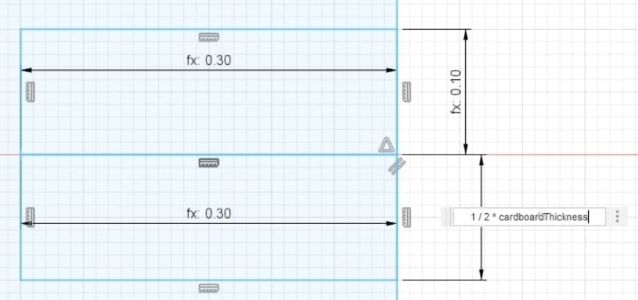
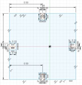
From here, I added two rectanges from the edge of the square that used slotDepth for the length out from the square edge and 1/2 of the cardboardThickness for the length of each rectangle.
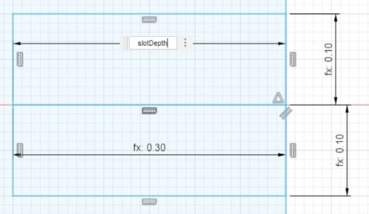
I then tested it with different sized parameters to make sure it was working correctly.
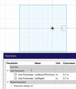
From here, I added the parametric hole to each side of the square:
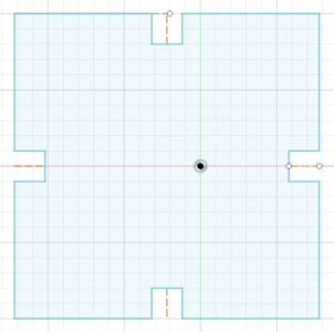
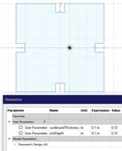
And finally I tested to make sure it worked with different parameters:
Making a New Piece¶
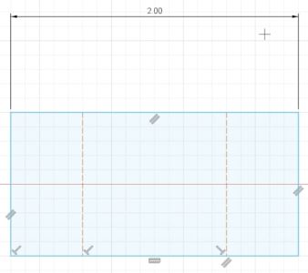
With the square piece done, I wanted to create a rectangle piece that way more creations could be made with the parts when they were cut. I began by sketching a 2x1 inch rectangle.
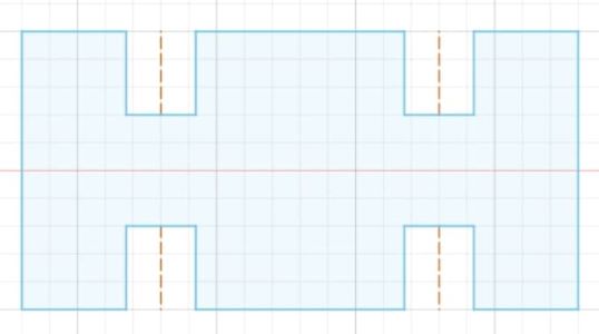
I repeated the process of adding the parametric inlets to each part I wanted the inlets at. This time I wanted two at the top and bottom and none in the sides.
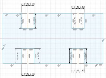
Then, I set the parameters to the correct cardboard thickness that I was going to use to cut.
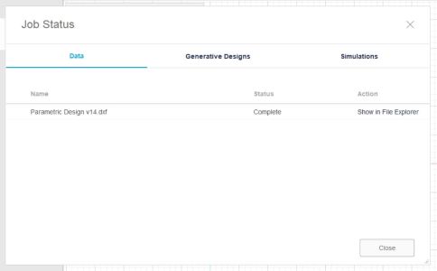
Then, I exported the sketches in Fusion to a .dxf file.
Laser Cutting my Kit¶
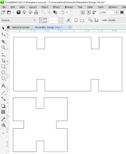
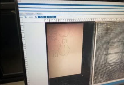
I then opened the .dxf in Corel Draw:
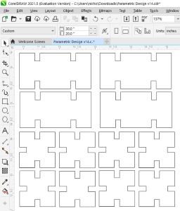
Then I created a ton of the pieces by duplicating the correctly scaled object in corel.
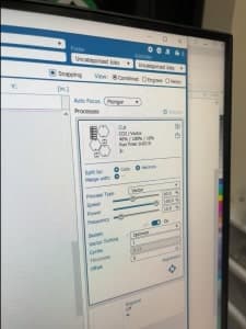
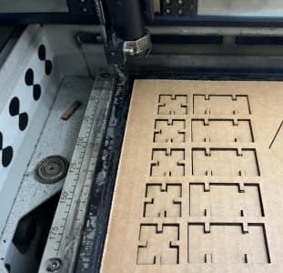
Finally, I hit “print” on the file in corel on the computer connected to the laser cutter, set the vectoring settings to cardboard, and let it run.
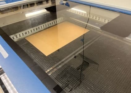
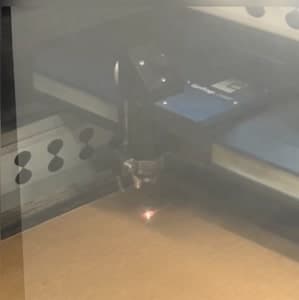
Keep in mind, me and my partner Aaron Logan cut together which is why you’ll see hexagons in the video, even though I didn’t design those.
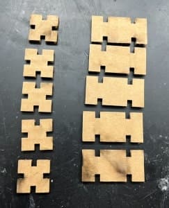
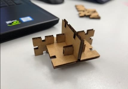
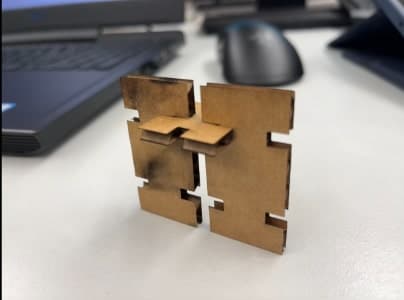
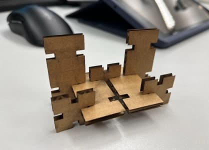
Here is the result:
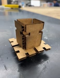
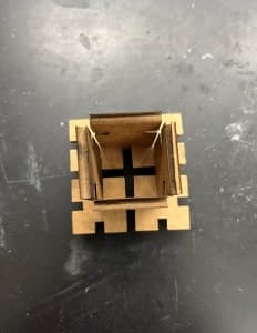
Building out of My Pieces¶
Downloads¶
§ Assignment 3: Group Work (Characterizing Kerf, Focus, Rate, Speed, Power) §¶
All group work is documented on your group site, found here.