Week 2: Computer Aided Design¶
This week I further developed my final project, created a complex vinyl sticker, and learned to use/refreshed my skills in many different CAD programs in preparation for later in Fab Academy.
§ Assignment: Model my Final Project & Provide Design Files §¶
For all my modeling and final project design, I chose to use Fusion360 as it was a program I was already familiar with and one which I felt was very versatile and perfect for my project. I also liked the cloud storage for my models so I could work on any device.
As you can see, there are many different designs and iterations I developed to get to my final models/ideas.
Changes to my Final Project¶
After the previous week, I realized that the scope of my final project was unnecessary and too big. The idea of having different units to form a custom garden was a good idea and was/still will be the goal, however, in a different way. What is the point of having the water tank, solar, and master all be different units when the garden would always require the same amount of those to function? In other words, if every garden you built (No matter the size) would need 2 solar units, 1 water tank, and 1 master no matter what size the garden was, why would they all need to be separate and put together? This is where my idea changed entirely. The new concept was to have only 2 units, a master and the garden. The master would have the chip and electronics, water tank, and solar/batteries all built into one unit, incredibly simplifying and making the design more efficient at the same time. The gardening unit however will still go unchanged.
Making the Models¶
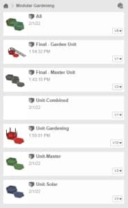
Prior to making the changes I just listed in the section above however, I still had the multi-unit idea in mind, so I went ahead and modeled what each unit would have looked like in fusion, these models seen below:
Below are the first models I designed for my final project. These would later be redone.
Garden Unit¶
Master Unit¶
Solar Unit¶
Water Tank Unit¶
But before I was able to model the water tank unit, I made the changes I listed above and combined most of them together. The updated models look like this:
Master All-Combined Unit¶
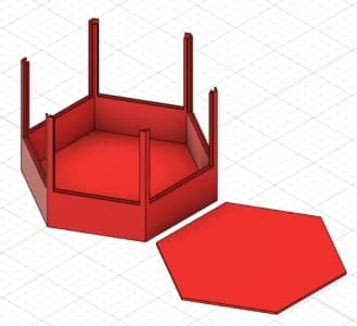
First Iteration¶
This above is the first design/iteration I made of the “All Combined Unit”, I had many issues with the sketch and it was poorly designed and rushed, so I decided to start fresh and redo the design, shown below.
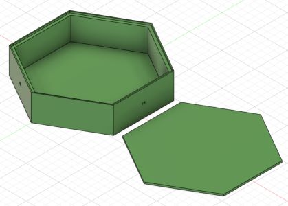
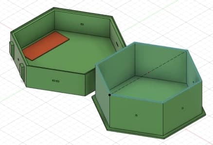
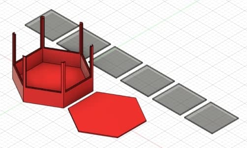
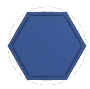
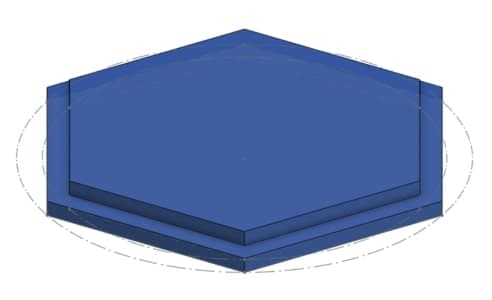
Second Iteration (Final)¶
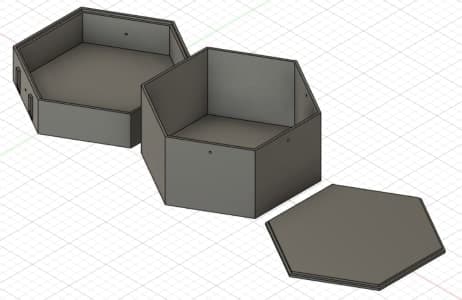
This version includes every single component needed to construct the master, minus the electronics. This design was much better put together and was put together much better and more uniformly so that if I need to make any changed I can easily go back in the timeline and make changes.
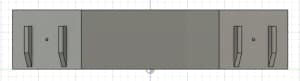
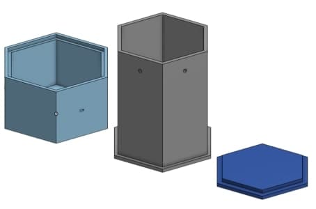
Far Left Object¶
On the far left object is the base. This is what will sit on the ground. The pieces coming off the side are mounts for the solar panels with a small hole in the middle for the 2 wires to go through. two of the six sides have these.
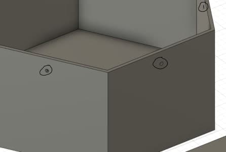
Middle Object¶
The middle object is what will sit on top of the base, it acts as a lid and a water tank. It has a small hole in it’s base for the wires that will go to the pump. This hole would be sealed when the wires are put through.
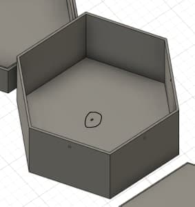
Additionally, for the pump’s output, there are 3 small holes at the top on the back panels which will lead the water to the gardening units.
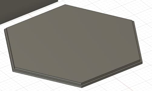
Far Right Object¶
Lastly, the object on the far right is simply a lid for the top of the water tank which sits on top in a small grove.
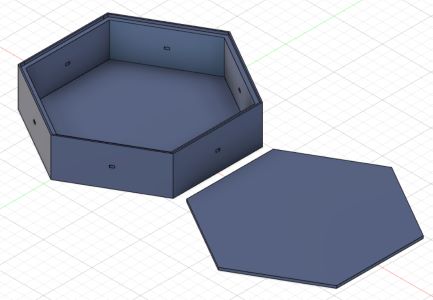
Newer Gardening Unit Design¶
Here all I changed was the addition of the panels.
With these changes I felt more confident in being able to go through with the project and also I felt as though the challenge of making it was much more tacklable.
Design Considerations¶
For dimensions of the planters I used the listed dimensions found through my research documented in week 1.
Creation of those Models¶
While I showed my final products, how did I create the models? What tools within Fusion did I use to create these models?
Sketching¶
When working with fusion, I always begin with sketching the base of a model. I incorporate the appropriate dimensions and scaling in these sketches:
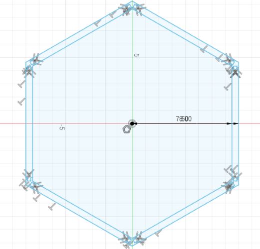
This allowed me to have tons of control over the design, but also it meant if I needed to make any changes to my model, I could go back in the timeline and simply edit this sketch for the desired results.
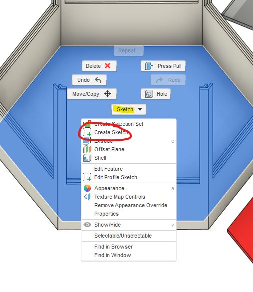
Creating a sketch can be done by simply right clicking in any blank space in a project or on the face of any object:
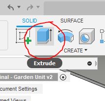
Extrusion¶
Extrusion is always the next step after working with a sketch. It allows a 2D design come to life in the third dimension. This is also added to the timeline similar to the sketch.
The tool for extruding can be found here:
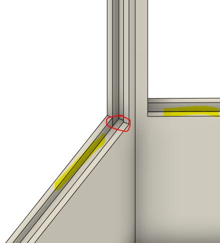
Additonal Sketch Work¶
After extrusion, if any further edits or shapes needed to be cut out of or added to the model, I simply would create another sketch plane on top of the face I wished to edit. This allowed me to create smaller features later in the design without having to restart at square one. Here are some examples of these implimentations:
Creating a sketch can be done by simply right clicking in any blank space in a project or on the face of any object:
Files¶
Master Unit Fusion File | Garden Unit Fusion File
§ Side Work: Using Other CAD Programs §¶
⚠️This section is work not assigned for Fab Academy, but was additional work I did on the side.
OnShape¶
Previously, I had only been using Fusion in order to make my models. While CAD doesn’t only pertain to 3D Modeling, I felt it would be useful to try a few other 3D modeling programs. My first program to try was OnShape. I decided to try and remake the Master Unit model I had made in Fusion which is displayed above.
Overall, I found OnShape to be incredibly similar to Fusion in so many ways. The only prominent feature missing was the timeline, as all objects or tools used immediately went to the hierarchy which made it very messy and annoying to use. Overall, I much prefer Fusion but it was important to try a different program.
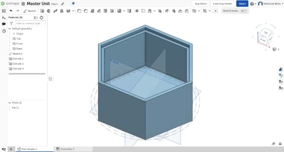
Sketching¶
I began by sketching. This part was very similar to Fusion, except I couldn’t figure out how to type in specific dimensions, leaving me to have to create a ton of lines in order to make the sketch at the proper dimensions.
Extruding¶
Extruding was also the same as Fusion, and I had no problems with it.
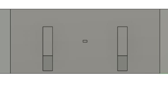
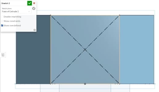
Creating Side Holes¶
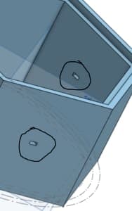
On my real design on the Master, there are small 0.25 in x 0.125 in holes on 2 of the sides for the wires of the solar panels to come in through. To do this in fusion, I created a cross-section using construction lines to find the midpoint of the face where I did a center point rectangle to that size. I did the same, however, once again, without the ability to type dimensions into my sketch, I had to try and get the numbers as close as possible to what they should be but they weren’t exact.
Mirroring those Holes¶
This is where the real pain happened when using OnShape. In order to create an identical hole on the other face, in Fusion, I would create a midplain between the two then mirror the extrusion of the first hole over that midplane, however, in OnShape, while they do have the mirror tool, I could not find a midplane tool. I messed around with the plane tool, but coudln’t get it to work, so in the end I reconstructed the hole from scratch on the other side without the mirror.
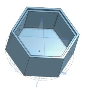
The Tank¶
Next, I designed the lid/tank that would be placed on top. In order to avoid useless repeating of what I did, I will simply show the final product. Once again, working without the mirror tool was annoying and difficult, but I just manually had to reconstruct all the objects which I wouldv’e mirrored which is fine.
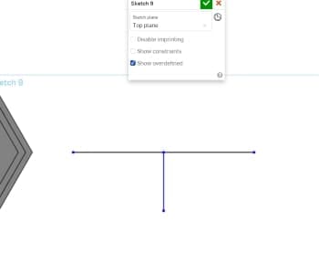
The Lid¶
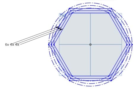
Lastly I went to model the lid. For this, I decided to take more photos and go into the process more then the tank since it was a different process then both the tank and the main piece. For the lid, I am 3D modeling it upside down essentially, as you will see. I began by sketching the correct length lines for the hexagons to later stretch to.
Then, I drew up the hexagons to scale using those guidelines, which were accidentally not set as construction lines, though that is no big deal as they can still be deleted without any problems.
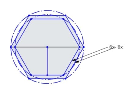
Lastly, I extruded each part of the sketch to their respective heights:
As you can see, one piece sticks out in the middle, and for the 3D printer to be able to print it I needed to model it upside down, as normally this lid would be face down, which is why the process is slightly different to that of the other pieces.
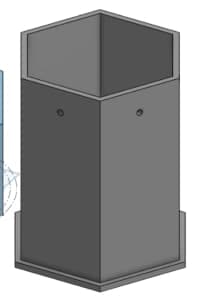
Final Product¶
Here is the finished remake of my fusion model but in OnShape:
Corel Draw¶
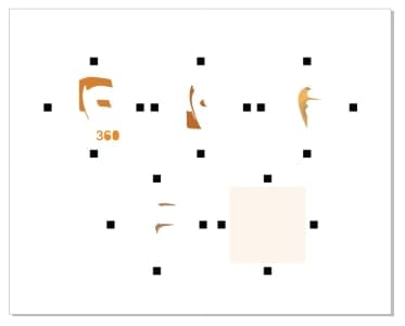
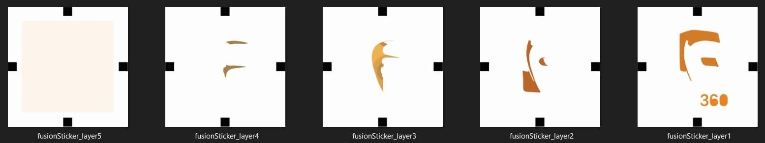
Using Corel Draw, a 2D platform which I have used in the past for Vinyl Cutters and Laser Cutters, my goal was to recreate the Fusion logo in different seperate layers as an SVG so I could use it in Silhouette Studio to cut a multilayered (for different colors) sticker.
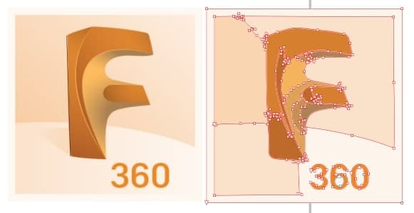
To do so, I opened Corel and began by importing an image of the fusion logo:
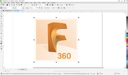
I then used the Quick Trace tool by right clicking on the image and hitting Quick Trace to trace the bitmap into editable vectors and lines.
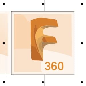
Now, I needed to add a black square in the same spot on each side of the logo. This was so that when I went to cut the actual sticker, I would have an indicator to line up all the layers with, or else I would be eye balling where to place each layer. This idea came from one of my fellow students in our fab lab, Aaron Logan. To do this, I created a square around the whole logo, then a larger square and place it on the center point of that smaller square, the point of the smaller square was to show where the center of the logo was, as I wasn’t able to find it without it.
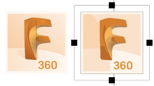
Now it was as simple as adding a square to each midpoint on each side of the large square.
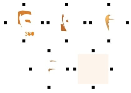
Now I removed both guide sqaures and began sorting. I essentailly would duplicate the black squares then select a black square from each edge and then select all objects with the same color which I chose to do for that layer, then I moved it to it’s own area. Here is what the layers look like sorted:
Finally, I resized it so that the sticker would be 5 x 5 inches per layer, and I also resized/refitted the Corel document settings so it fit to the page, then I exported the SVG. Here is the final product:
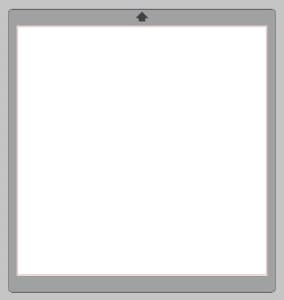
Silhouette Studio¶
Silhouette Studio is a tool used to process and edit SVGs and to prepare them for Vinyl cutting. Since I had already designed an SVG, all I had to do was import it into Silhouette Studio and touch it up and separate it for cutting on the Vinyl Cutter.
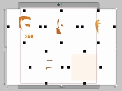
A Challenge¶
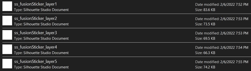
As I quickly found out, SVGs cannot be imported into the version of Silhouette Studio that I owned. I tried exporting for Corel and into it as a JPG, but doing it this way wouldn’t let me chop up the image into the separate layers, so as a result I had to go back into Corel and export each layer individually as a JPG and into Silhouette individually so it would be ready for when I cut the next day. Doing this was a pain, but a learning experience at the same time. 6.528
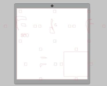

Now, I imported each layer into Silhouette Studio, traced it, scaled it, and saved it to my computer for cutting tomorrow.
The rest of the actual sending to cutter and cutting process will be under the “Vinyl Cutting” section below this.