Week 13: Networking and Communications
This week I explored communcation between chips and boards through networking.
Assignment #1: Design, Build, and Connect Wired or Wireless Node(s)
My Idea
What I wanted to do was similar to what was in the lecture, a ton of mini boards wired to eachother then to the programmer. I want to be able to have the boards communicate with eachother and receive commands from the computer that only go to certain boards.
Research & Lecture Review
I looked into the resources that were looked over in the lecture and which were listed in the week schedule. I found this project here, which used a 412 chip which I was familiar with to communicate between multiple boards. This page was made by Adrián Torres. This project would help me understand Rx and Tx and networking while guiding me in the process so I wouldn’t be completely lost. Here is a video which Neil had shown which is what I hoped to achieve (of course with changes and customization) here.
Updated Idea
I looked over the documentation of Jack Hollingsworth who at the time was sitting next to me, so I also asked him a few questions. From this discussion, I gathered that any serial write on outputs signal on the Tx pin which can be read on a seperate chip on the Rx pin assuming both are on the same baud rate. Knowing this, I wanted to have a large master board which had 3 buttons and this board would be connected to the programmer on one side and on the other it would connect to a chain of 3 smaller boards who have buzzers and an led. The goal was to be able to press one of the buttons on the main board and have one of the chained board’s light turn on and the buzzer make a sound. The buzzers would all have different resistance too as to have them make different sounds.
Testing Buzzer Sounds on an Arduino
I placed parts on a breadboard based on my idea:
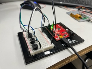
And copied the code from a tutorial found here. From here, I modified the code to get this:
const int buzzerOne = 8;
const int buzzerTwo = 7;
const int buzzerThree = 6;

void setup(){
  pinMode(buzzerOne, OUTPUT);
  pinMode(buzzerTwo, OUTPUT);
  pinMode(buzzerThree, OUTPUT);
}

void loop(){
  delay(1000);
  tone(buzzerOne, 1000);
  delay(250);
  noTone(buzzerOne);
  tone(buzzerTwo, 900);
  delay(250);
  noTone(buzzerTwo);
  tone(buzzerThree, 800);
  delay(250);
  noTone(buzzerThree);
}
This included the base 3 buzzers which I would use to make different frequency sounds at the same time if needed.
And this worked:
Of course, in the final each buzzer would be on a seperate board and such so this test was mainly to get an idea of what the code and wiring for the buzzers would need to be.
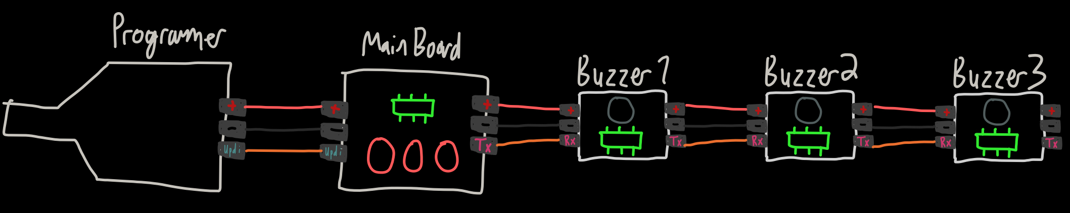
I then went to draw up my design in notability for my board chain and master board. I ended up with this sketch:
Next I went to design it in KiCad.
Kicad Design
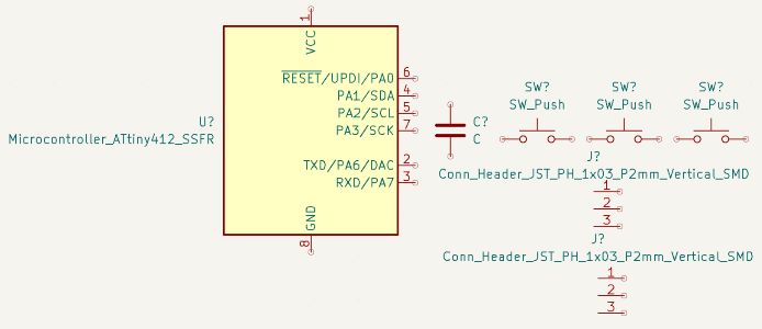
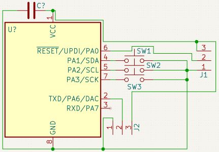
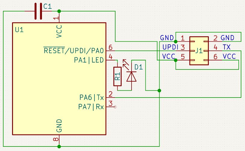
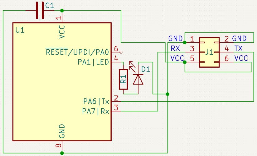
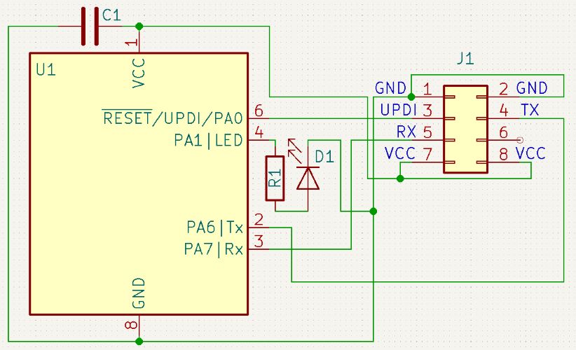
I began by creating a blank KiCad project adding 3 pin headers, a tiny 412, a 1 uF capacitor, and 3 buttons.
Using the pinout chart:
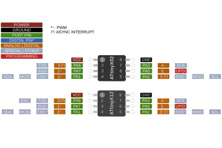
And found out the Rx pin would be PA7 which is Arduino pin 1 and then Tx pin would be PA6 which is Arduino pin 0. Then, I decided to hook up each of the three buttons to PA1 (2), PA3 (4), and lastly PA2 (3).
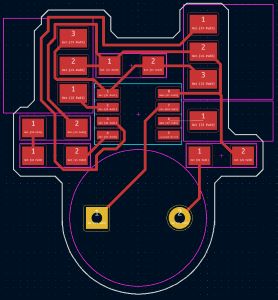
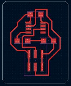
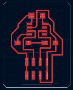
Then I took it into the PCB editor:
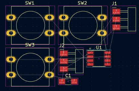
And reorganized it into this:
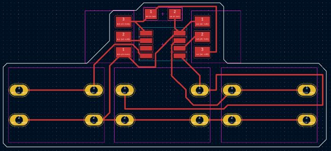
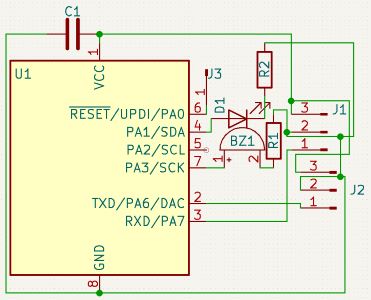
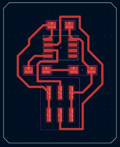
And that was the main board done. I then pulled into a new project the components for one of the chain boards. I wired them correctly to get this:
And used the PCB editor to get this:
And with that the first prototype designs for my boards were done. I now wanted to work and get the code good by modifying my other buzzer code.
The Code
I first researched Rx and Tx communication tutorials for Arduino. I found this one and followed it. From the example code here and also my previous buzzer code, I wrote the following two:
This code is for the main board which will send out a signal based off button input. For my first prototype, I simply wanted to test the Rx and Tx before using buttons hence why this code doesn’t include any inputs.
 void setup() {
    Serial.begin(9600);
 }

 void loop() {
    delay(5000);
    Write(0); //Sends a signal to the first board to blink
 }

void Write(int id){
  Serial.write(val);
}
This code is for the eventual buzzer board, this code is done entirely with all of the eventual features.
int idPassed;
const int localID = 0;
const int localTone = 1000;
const int buzzerPin = 4;
const int ledPin = 2;

void setup() {
  // Begin the Serial at 9600 Baud
  Serial.begin(9600);
  pinMode(buzzerPin, OUTPUT);
  pinMode(ledPin, OUTPUT);
}

void loop() {
  Serial.readBytes(idPassed);

  if (localID == idPassed){
    //Sent message is designated for this board
    Activate();
  }
  else{
    //Sent message is for a board further down the chain
    Write(idPassed);
  }
}

void Write(int id){
  Serial.write(val);
}

void Activate(){
  digitalWrite(ledPin, HIGH);
  tone(buzzerOne, 1000);
  delay(250);
  digitalWrite(ledPin, LOW);
  noTone(buzzerOne);
}
Prototype 1
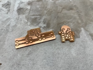
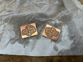
I wanted to mill, solder, and program both of these boards excluding the buzzers and buttons to test the communcation. I sent my files and began milling both on the same sheet.
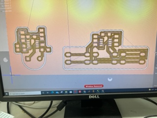
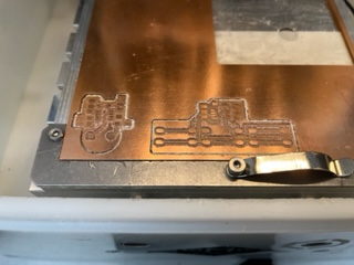
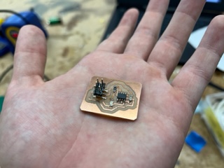
And got these:
And then I gathered the components and soldered:
From here, I went through and individually programmed the boards. After some failure, I spoke with Dr. Harris, and he helped me re-write some of my code where I had this:
MAIN BOARD
void setup() {
  Serial.begin(9600);
}

void loop() {
  delay(5000);
  Serial.print(0);
}
BUZZER BOARD
byte inByte = 0;
const byte id = 0;sssssss
const int ledPin = 2;

void setup() {
  // Begin the Serial at 9600 Baud
  Serial.begin(9600);
  pinMode(ledPin, OUTPUT);
}

void loop() {
  if (Serial.available() > 0) {
    // get incoming byte:
    inByte = Serial.read();

    if (id == inByte){
      //Sent message is designated for this board
      Activate();
    }
    else{
      //Sent message is for a board further down the chain
      Serial.print(inByte);
    }
  }
}

void Activate(){
  digitalWrite(ledPin, HIGH);
  delay(2500);
  digitalWrite(ledPin, LOW);
}
But it still wasn’t working. My jumper headers also kept coming off and the way I designed the boards meant that the pinouts conficted physicaly and I had a jumbled mess of wires.
So I decided to void the buzzer idea, redesign & recode, and to simply do a string of Rx Tx communicating-LED blinking boards to make it simpler and to do it better.
The Remake
I remade the Main board first in the schematic editor and then the PCB editor to get these:
And then I went to redesign the smaller node board:
And then I rewrote the code to get this:
MAIN BOARD
const int ledPin = 2; //Pin # of LED

void setup() {
  Serial.begin(9600);
  pinMode(ledPin, OUTPUT);
}

void loop() {
  delay(2000);
  Activate();
  Serial.print(0, DEC);
}

void Activate(){
  digitalWrite(ledPin, HIGH);
  delay(500);
  digitalWrite(ledPin, LOW);
}
NODE BOARD
int inByte = 0; //Recieved Byte
const int id = 0; //Local Node ID
const int ledPin = 2; //Pin # of LED

void setup() {
  Serial.begin(9600);
  pinMode(ledPin, OUTPUT);
}

void loop() {
  if (Serial.available() > 0) {
    inByte = Serial.read();

    if (id == inByte){
      Activate();
    }
    else{
      Serial.print(inByte, DEC);
    }
  }
}

void Activate(){
  digitalWrite(ledPin, HIGH);
  delay(500);
  digitalWrite(ledPin, LOW);
}
Then I milled these new boards. Notable differences in my milling process are as follows:
- Trace Clearence in the Bantim software of 2 mm
- Trace Width in KiCad to 0.5 mm
- Larger Board Outline & Box Shape for Ease of Post Processing
They looked like this:
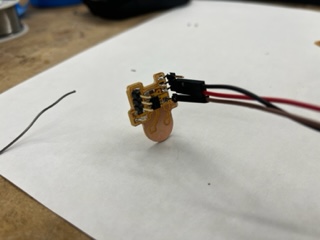
Then I soldered both correctly:
And finally programmed. I first programmed the main node board with sucsess and got the light to blink:
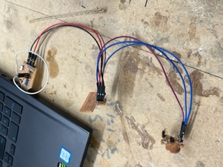
From here I went to program my node board but there was one big issue… I never created a UPDI header. LUCKILY, I put it jumper to it while programming and the code was able to transfer safely, but I noted I needed to add the headers to my node design. Then I wired both the Node and Main together and tested if they could communicate, and with this, they wouldn’t. After speaking with Alaric Pan, who was also doing Tx Rx, I realized some of my syntax with interpreting the incoming serial was off. From this, I changed the Node’s code and pushed with the code seen below:
int inByte = 0; //Recieved Byte
const int id = 0; //Local Node ID
const int ledPin = 2; //Pin # of LED

void setup() {
  Serial.begin(9600);
  pinMode(ledPin, OUTPUT);
  Activate();
}

void loop() {
  while (Serial.available()==0);
  int incoming = Serial.parseInt();
  if (incoming == id){
    Activate();
    delay(500);
  }
  else{
    Serial.print(incoming);
  }
}

void Activate(){
  digitalWrite(ledPin, HIGH);
  delay(500);
  digitalWrite(ledPin, LOW);
}
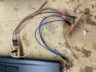
And this worked perfectly.
This first video is very in depth and long. If you want to simply see the final product, check out the second video!
With this sucsess, I wanted to alter my node design in KiCad to include the UPDI for the future or for people who wanted to use my files.
Node Modifications
I made the 3x2 pin header in my project for the Node to a 4x2 to get this:
And fixed it up in the PCB editor:
And now everything was done! I am writing this on Tuesday late at night and I hope to add 2 additional nodes to my circuit tommorow to prove my concept better, but for now to complete the assignment “Design, Build, and Connect Wired or Wireless Node(s)” (which I do in fact have a wired node to a main board using an ID system) I wanted to finish my documentation.
Dowloads
Assignment 2: Group Work (Send a Message Between Two Projects)
All group work is documented on your group site, found here.
I contributed by doing the majority of the coding, wiring, and most of the written documentation. I wrote the code with Jack for the first two networked arduinos and did some of the wiring between the Arduinos.
Week Summary
Overall this week was super important. I learned how to properly communicate between boards, something I’d need to likely use down the road in the future, even if it wouldn’nt be included in my final. I found it very interesting and satisfying to do so. I learned different types of communication, such as what I used, Rx and Tx, but also things like I^2C and FTDI even though I may not have used them.