8. Computer controlled machining
Individual Assignment
For this week I had to design something big that can be cutted in the CNC. After having the design we need the CAM for milling. Definitely, my design should a kind of furniture, so I looked for some ideas on the internet.
Idea
Our instructors asked us to design something big but I prefered to do something small because it was my first time practicing with the bigger CNC. In my case, my priority is learning and practicing the workflow process that allows me to find my mistakes and then challenge myself. After this introduction, I decided to design a chair with all the characteristics to accomplish the goals for this week which are including curved surfaces and not using fastenersor glue.
Design
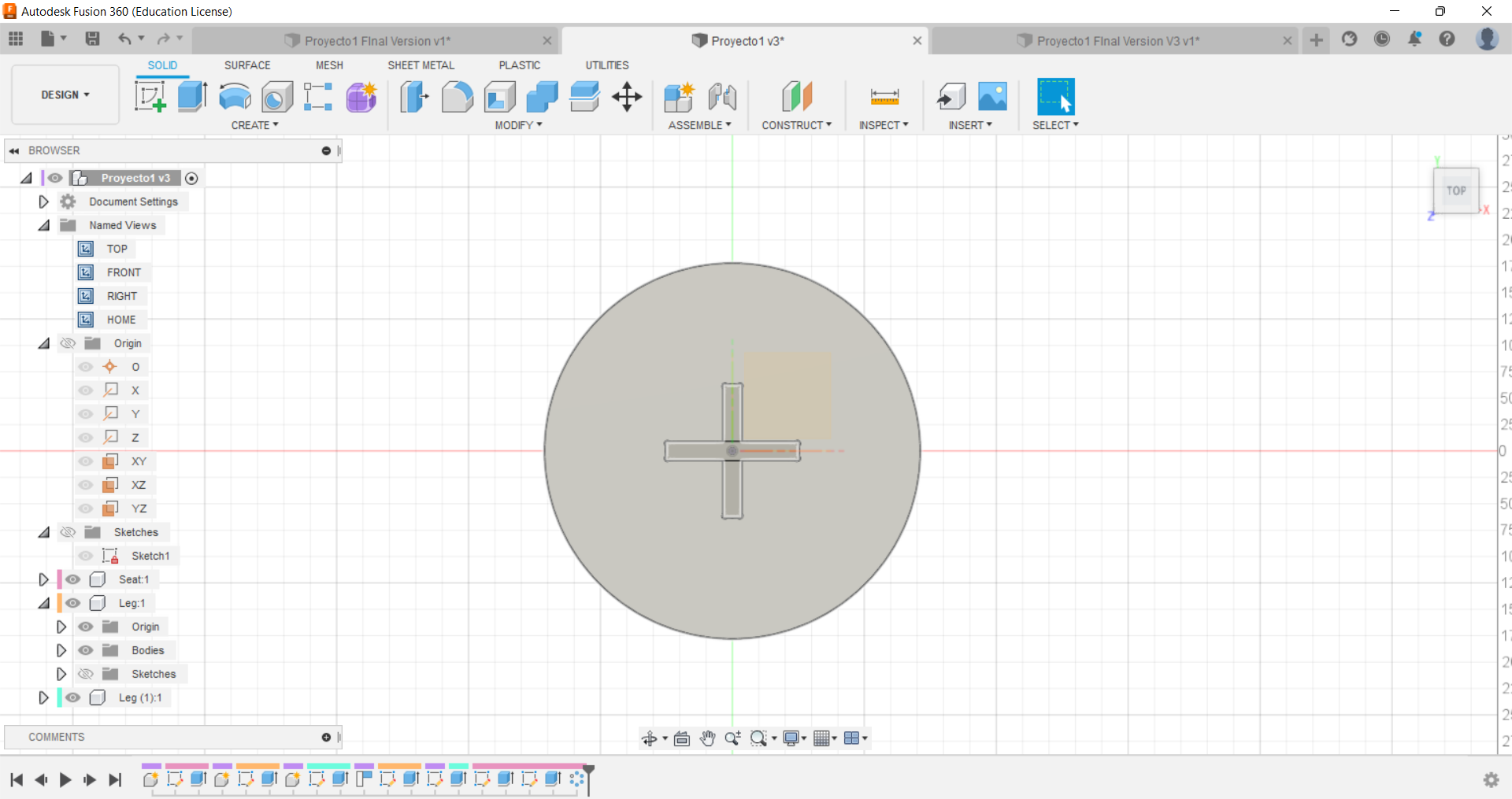
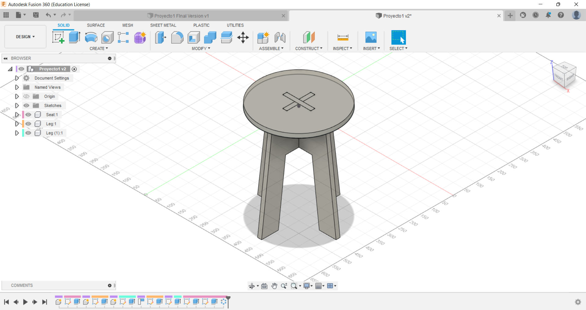
My chair was designed in Fusion 360 (definitely, it is my favorite software) but first I made a sketch because I did not have any idea of the dimension and how to assemble it. Afterwards, I started to design in the software a circle to become it in the seat with the extrude command. Then, I sketched the two leg.
.png)
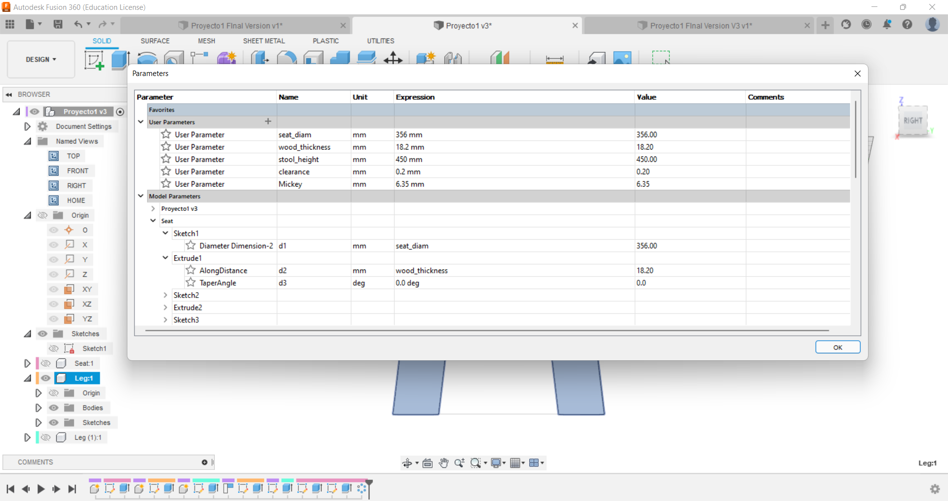
Something very important that I recommend you is to create the parameters because for this kind of design probably you will need to adjust any value and with this command you only change the value and it will affect all the model. In my case, I did not know the thickness of the wood but with this command it did not get me too much problem. However, it is better measure the material before starting whit the design.
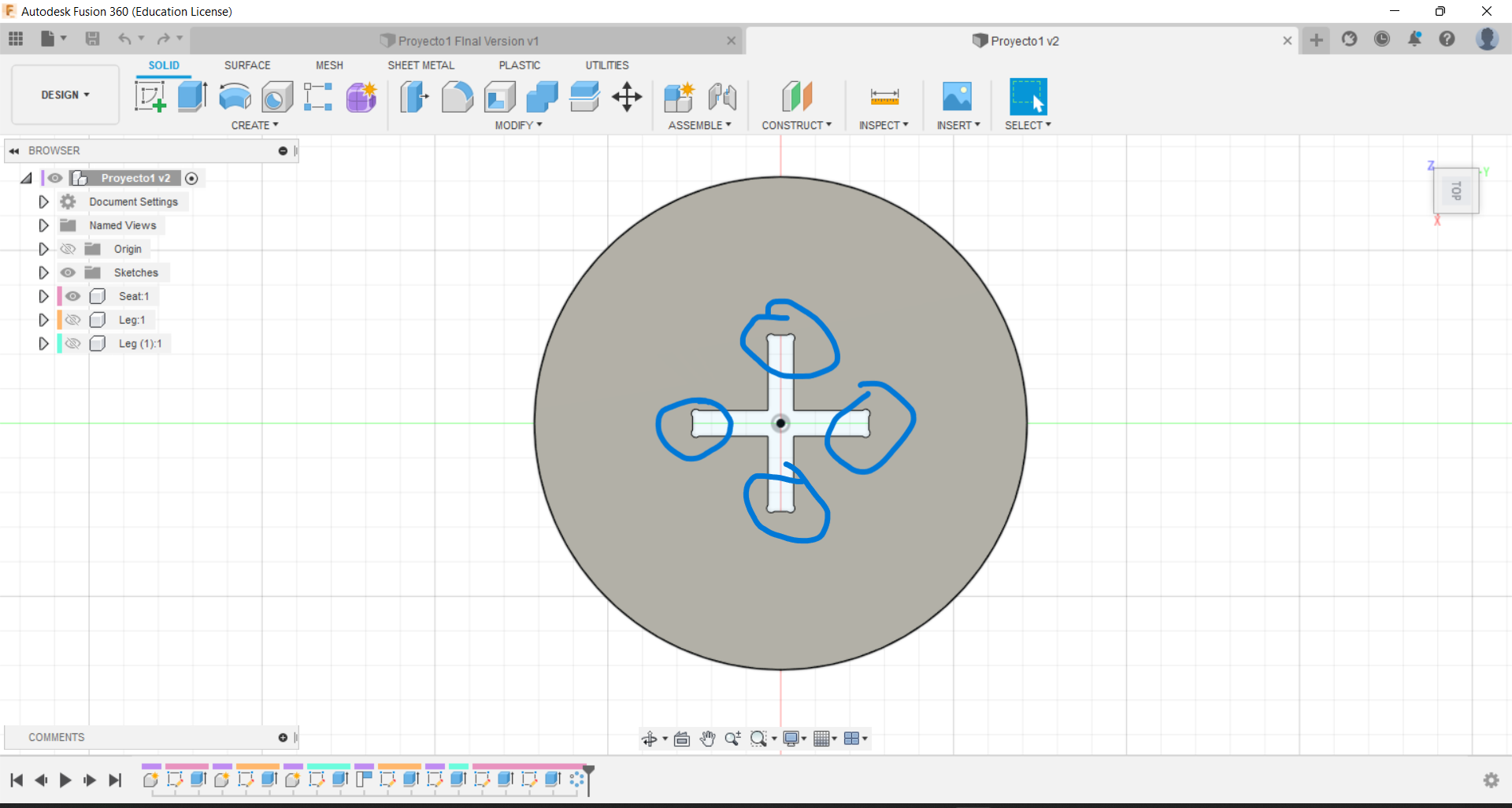
Then, I created the holes that allows me to join the two legs and the legs with the seat. Another thing that we have to take in consideration is the clearence, if you see my parameters I defined it a value of 0.2mm
I let this photo just to remind you.
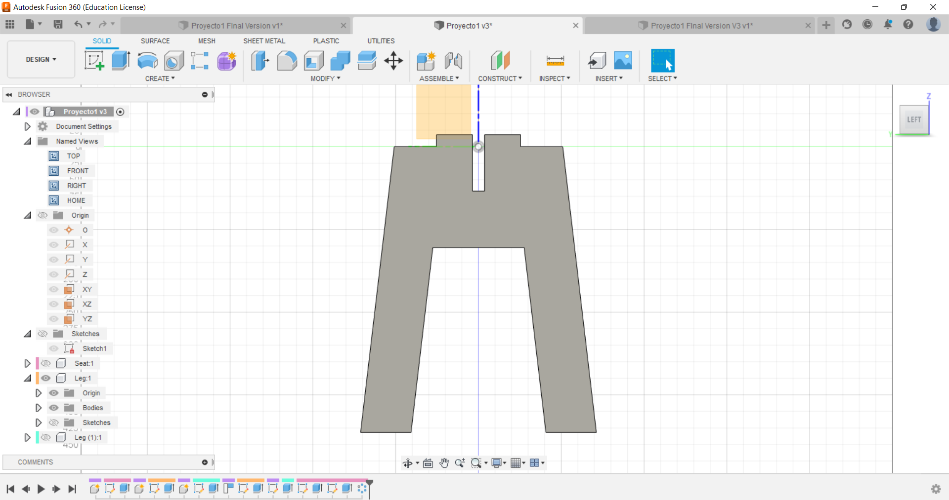
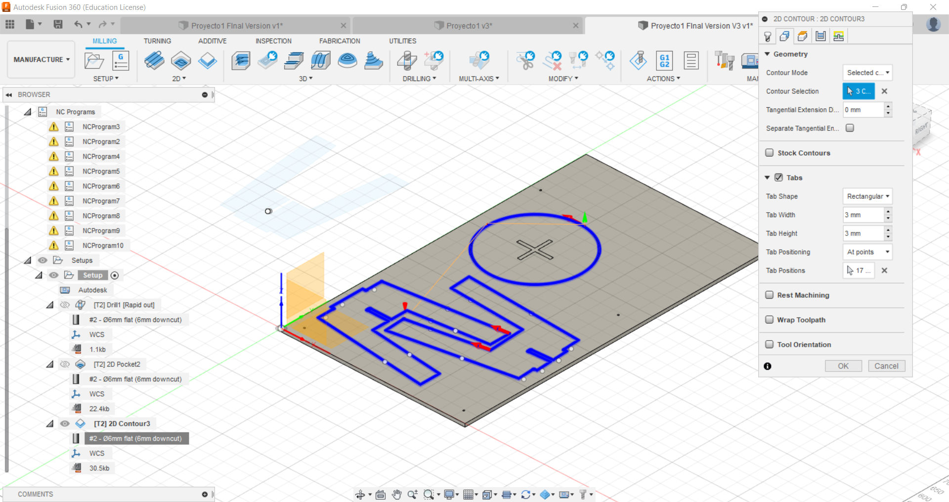
On the other hand, Dog-T bones are needed to allows the mill to avoid cutting a corner with a sharp angle because it does not help to join the pieces. For example I created T-bones in my design.
This a screenshot of my final design.
Finally, Nesting is putting all the pices in one plane because the CNC machine cuts models in this way. One important advice, do not forget draw the screw on the corner of the table, I forgot it and it was not to easy add it.
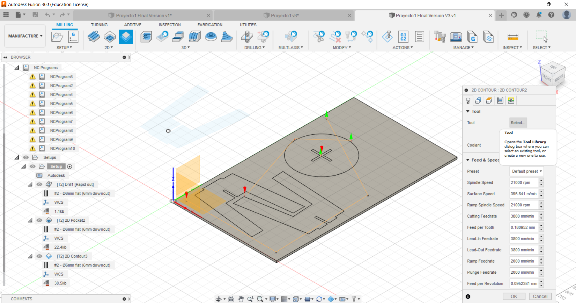
CAM
In my case I did the CAM in Fusion 360 as well because I wanted to try something different instead of RhinoCAM and also I saw this option in the manufacture workspace and it seemed easy to use. So, in my case due to my design, these operations were created:
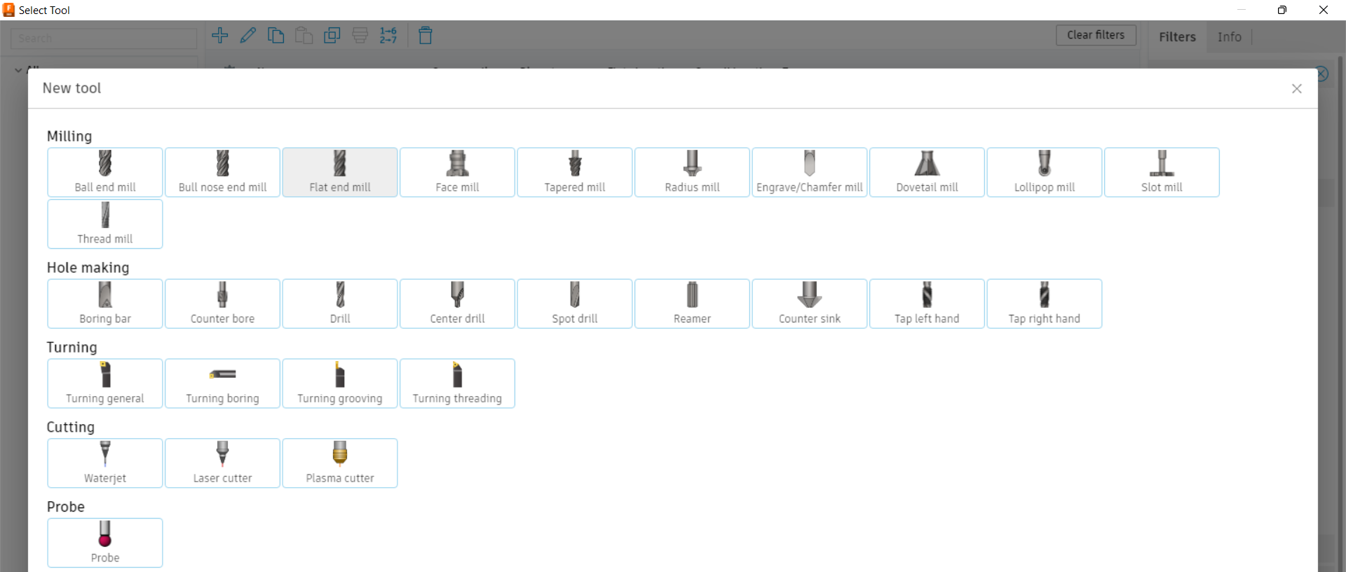
New tool
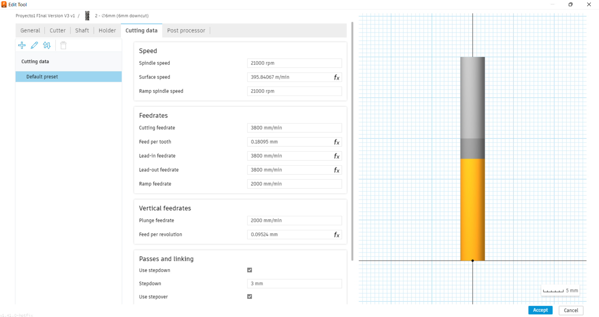
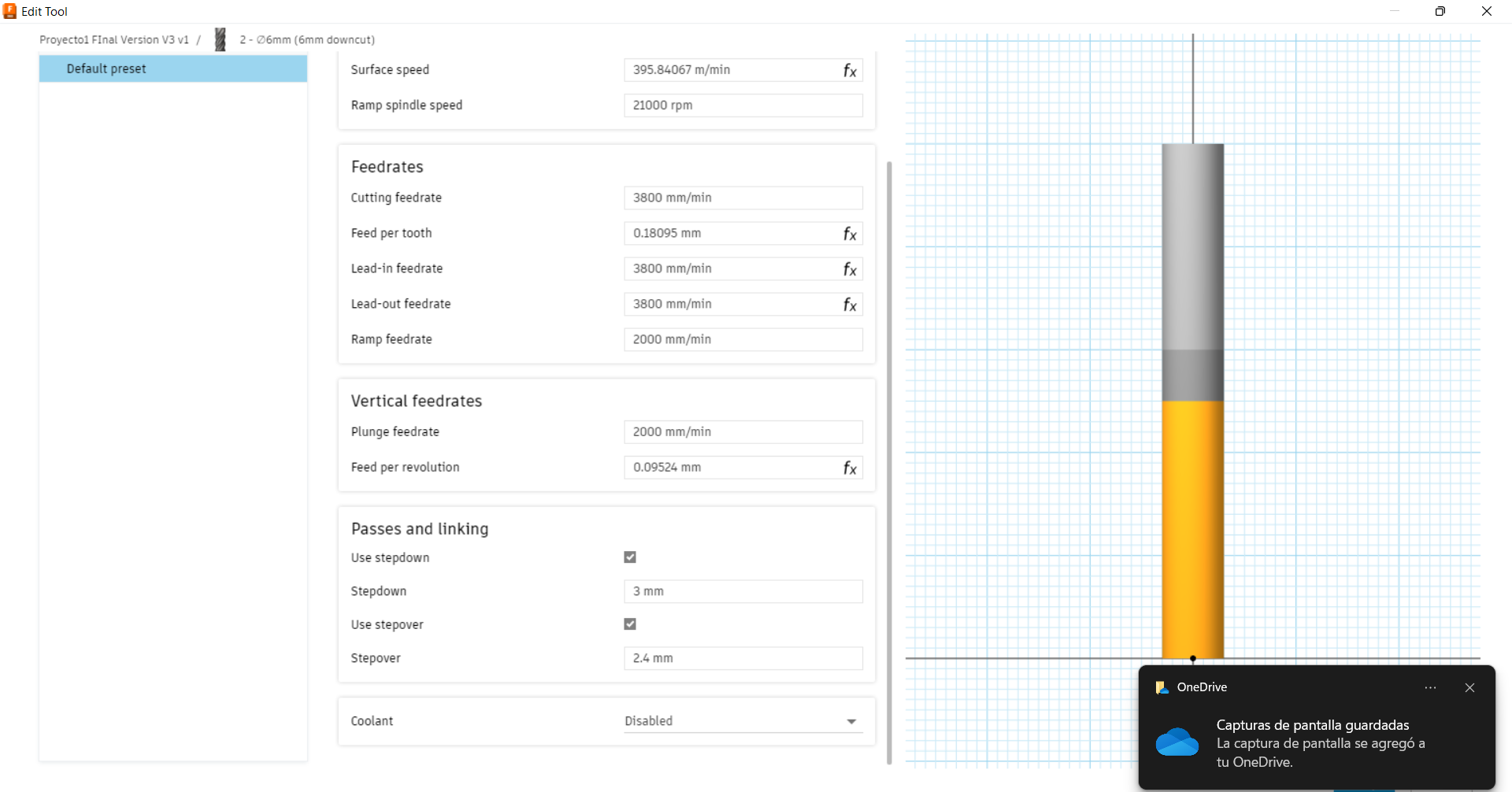
My tool was not available in Fusion 360 so I created it. I needed a ∅6 mm flat mill for all the operations. To create this mill I chose one operations and then I had to select a tool and I must go to the symbol “+”. Here, I defined the mill with the following parameters:
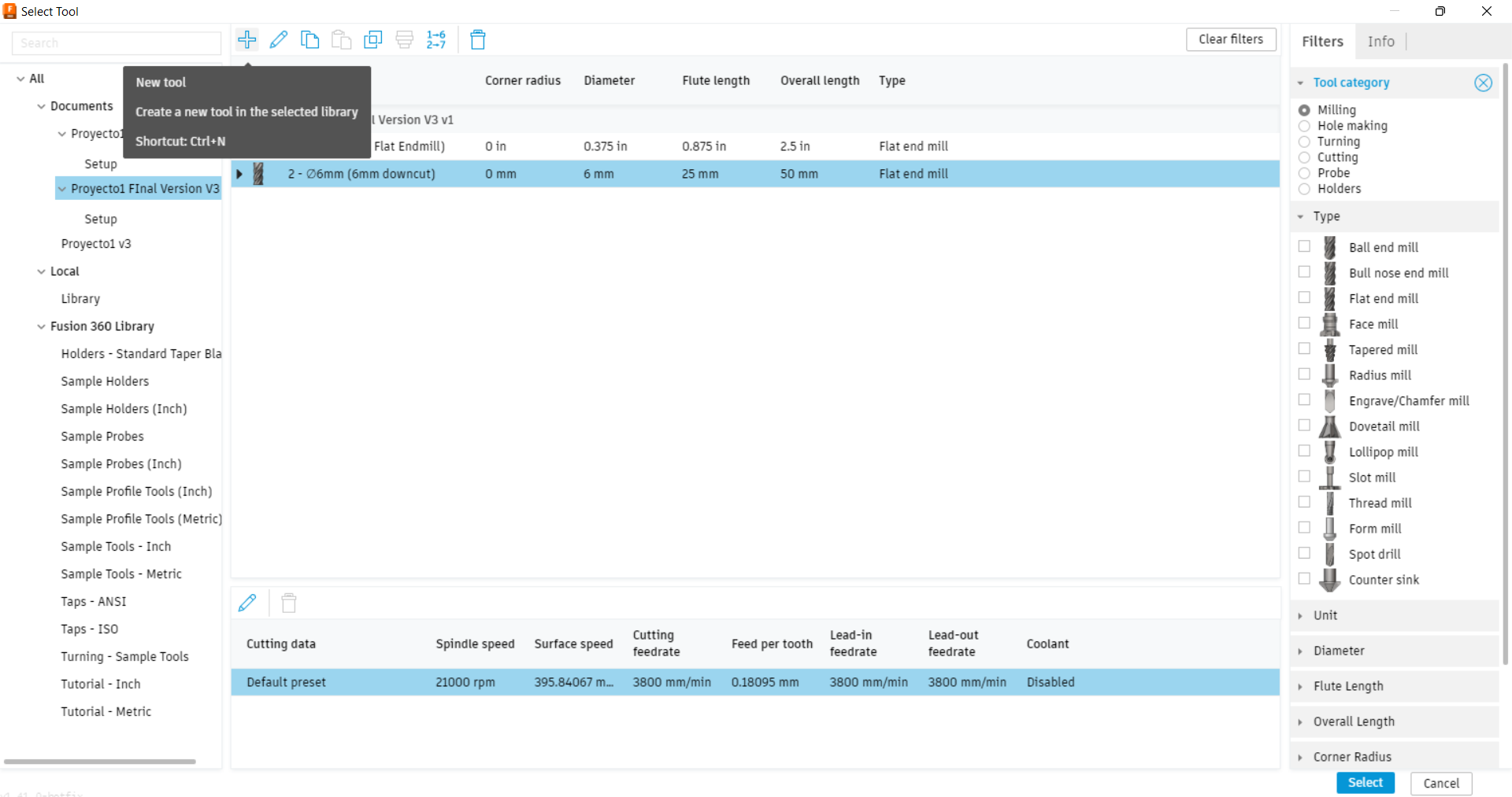

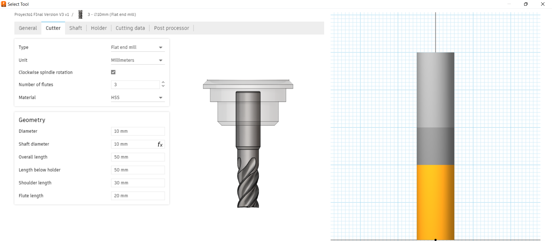
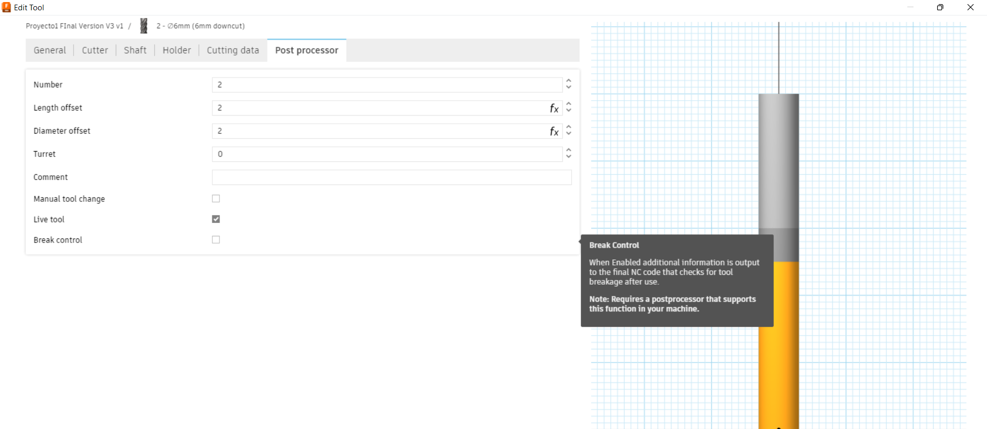
As you can see in the next pictures, the tool was added in the others operations.
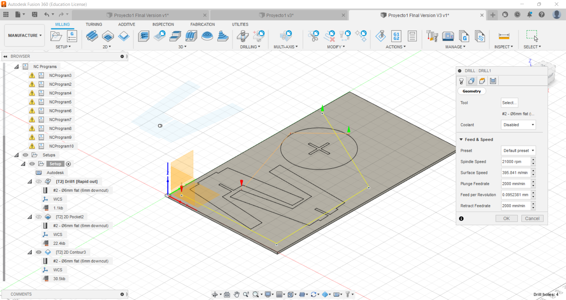
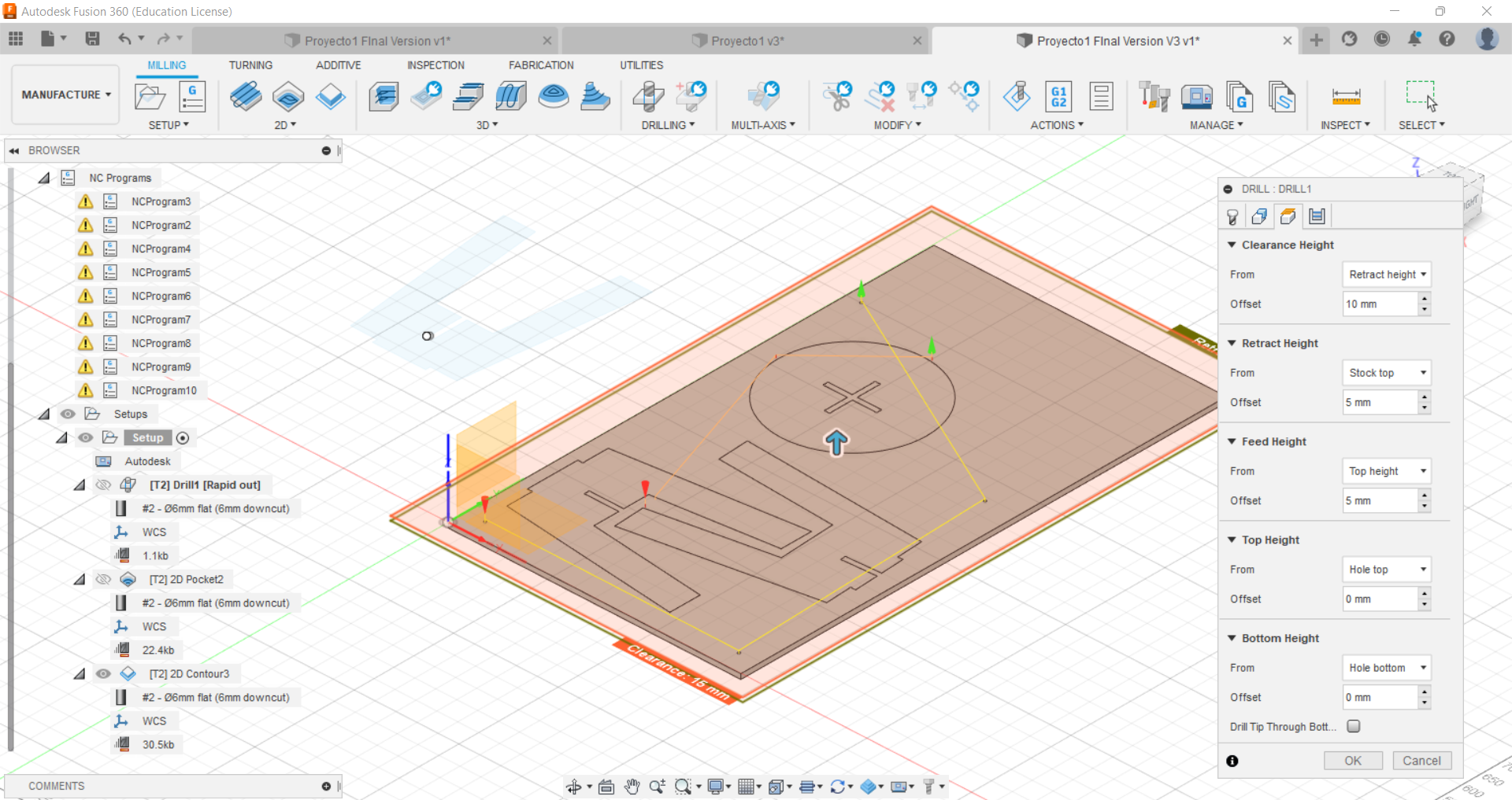
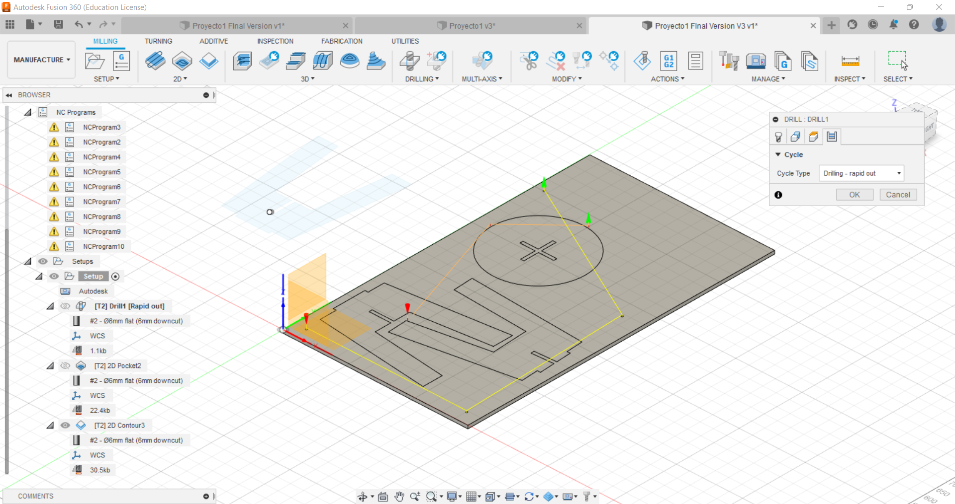
Drill
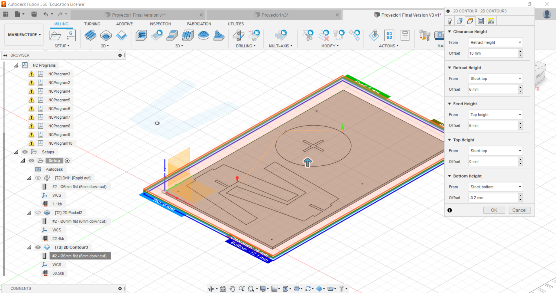
I used drill to mark the holes for the screws. In this case the feeds and speeds were: 2000mm/min and 21.000RPM. I set the clearance plane to 10mm to avoid any colission The entry and exit dind’t need any aproach because it was just to mark holes.

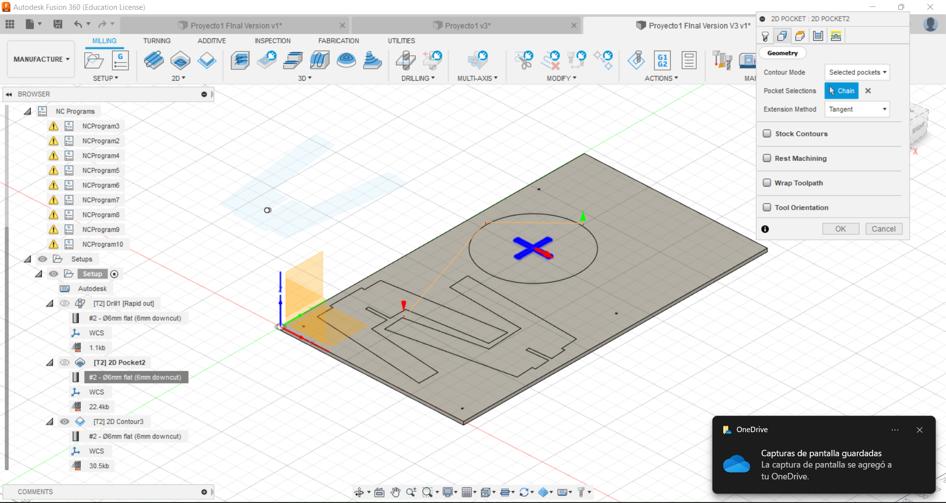
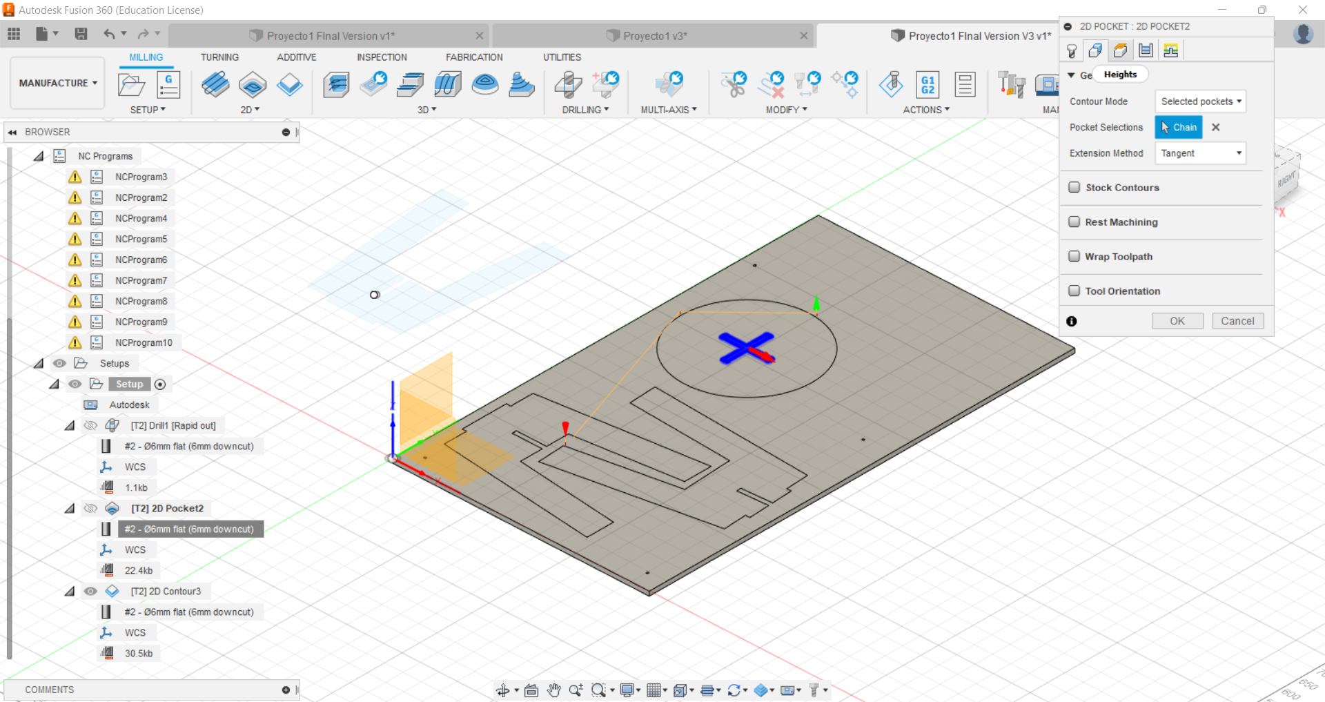
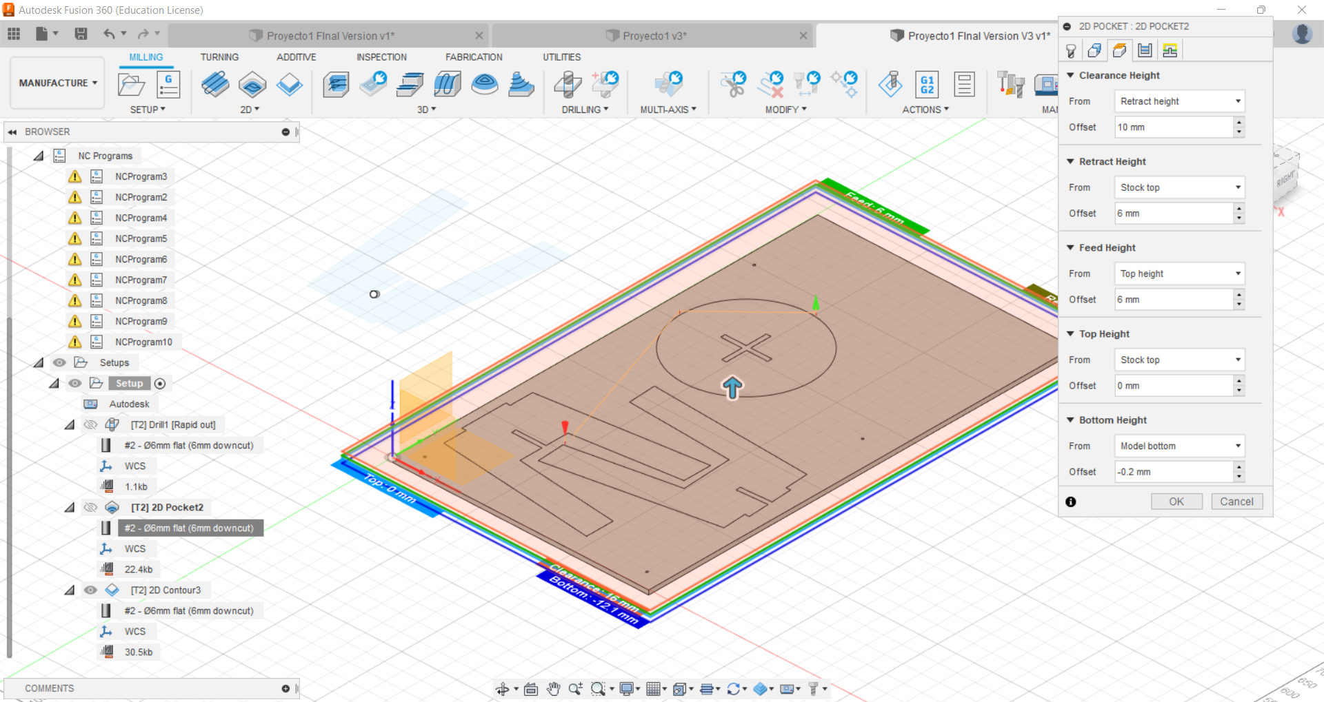
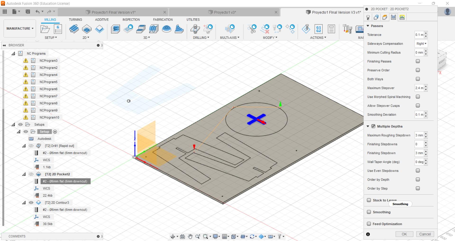
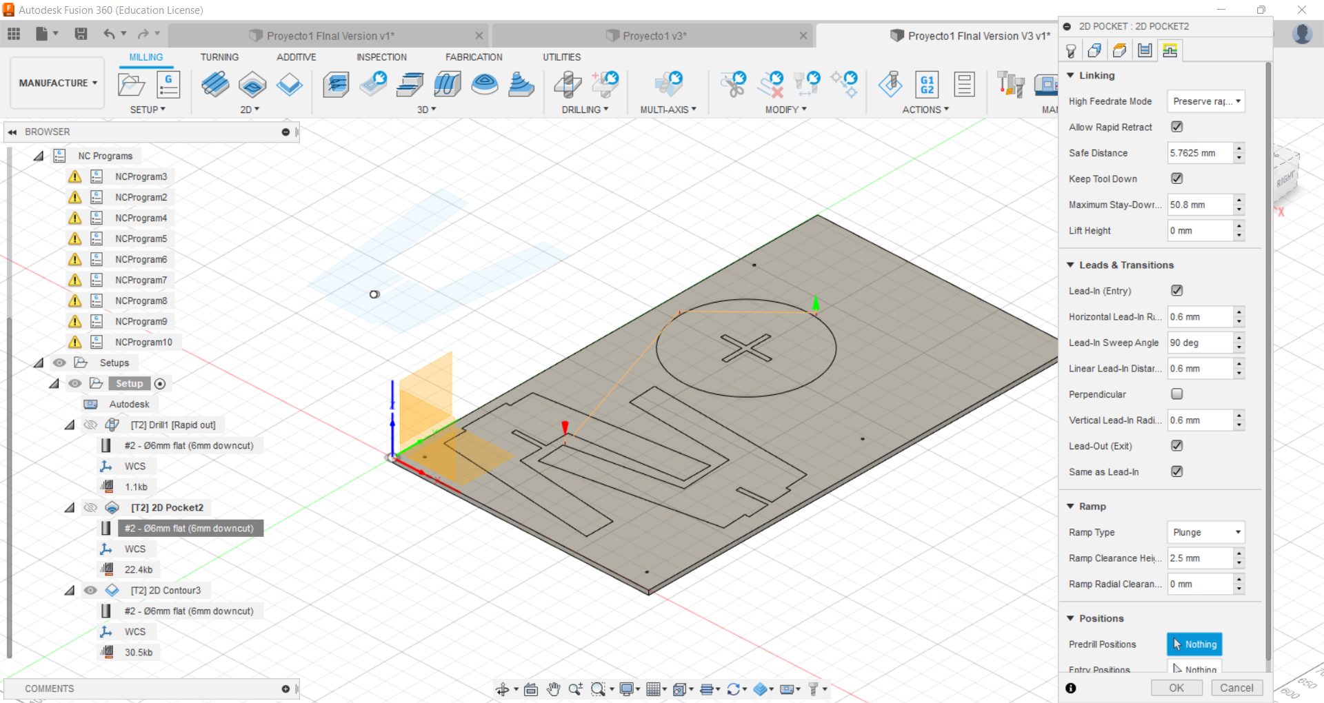
Pocket
the feeds and speeds were: 3800mm/min and 21.000RPM I used pocketing to make the insertions for the joints, and also to make the insertion for the cap of the bench.
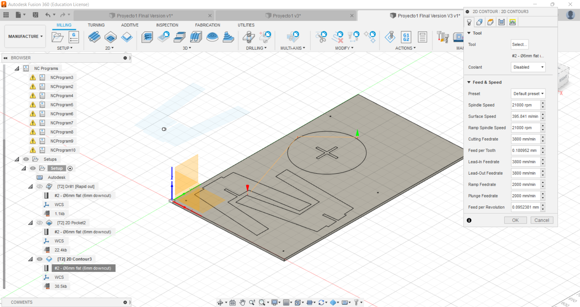
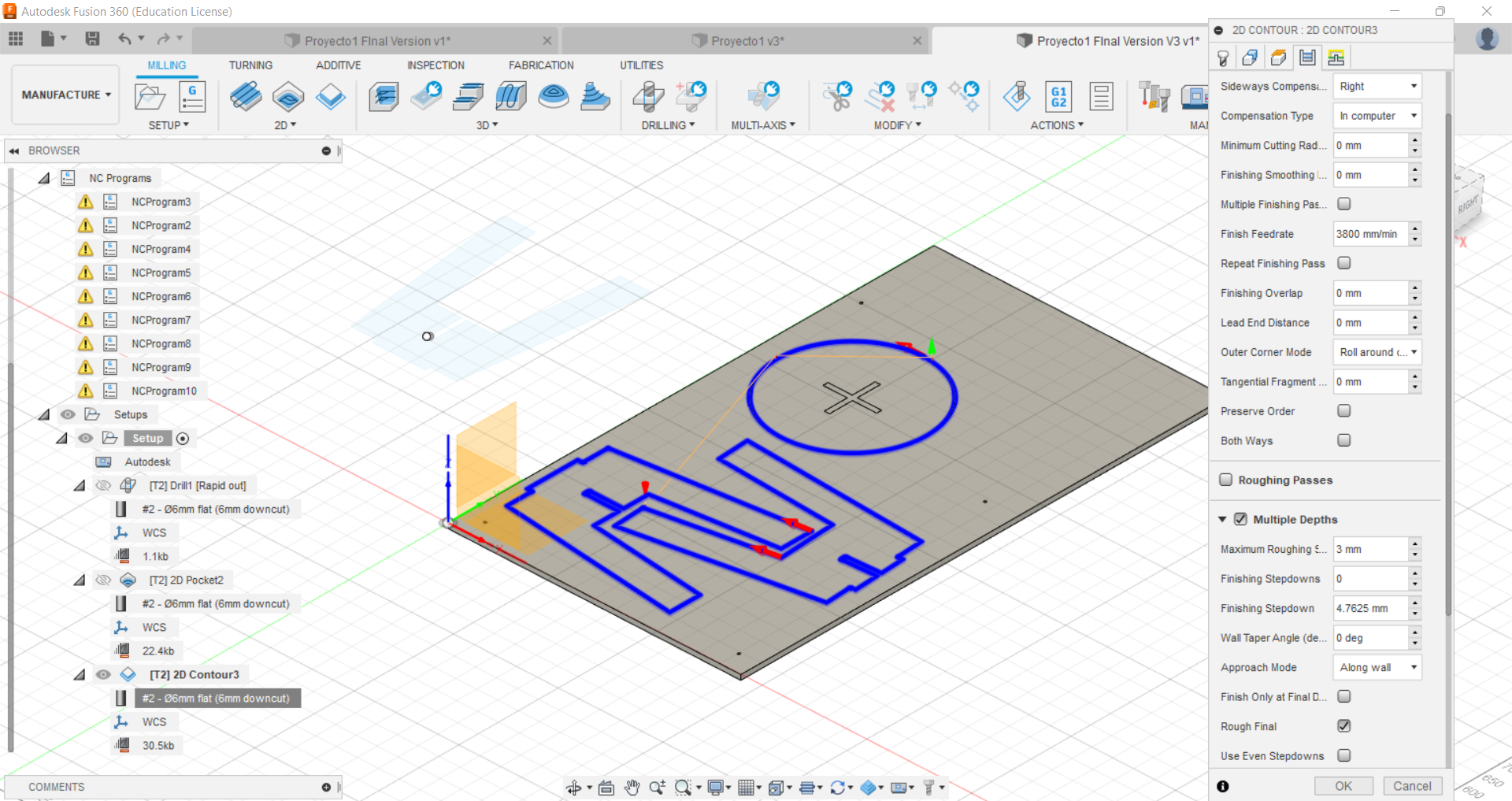
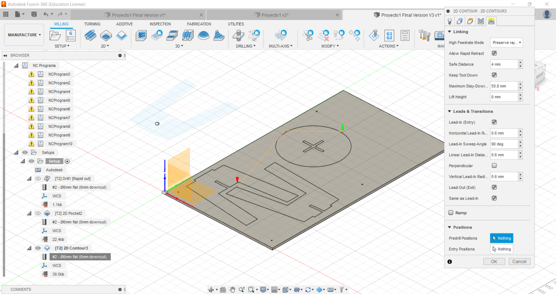
Contour
the feeds and speeds were: 3800mm/min and 21.000RPM
CNC milling
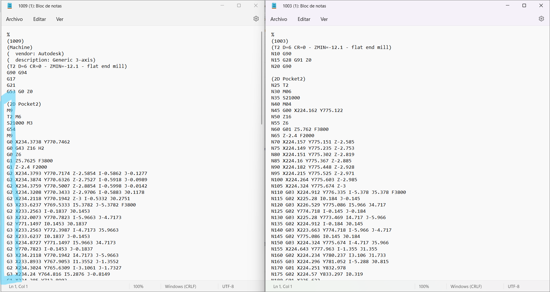
In this stage I had some problem because when I downloaded the G-Code, the CNC machine was not able to read it from Fusion 360 because there were components with letter “N” in the file. I thought that I had to design my model again but Joseph (He has been helping me a lot during this weeks) told me that we could download a library that allows me to cut my design.
Fortunately, Joseph got the library (known as Autodesk_HSM_beamicon2.eps, do not worry, I am going to upload it in my files section) and when we download again the file although the letter “N” had disappeared, the coordinates was starting with G1, G2 and G3 instead of G0 (which is the first component of line code in RhinoCAM). In the following picture, you can see what I am talking about because on the left picture there are G codes but on the right picture the G codes have been eliminated due to the Autodesk file:
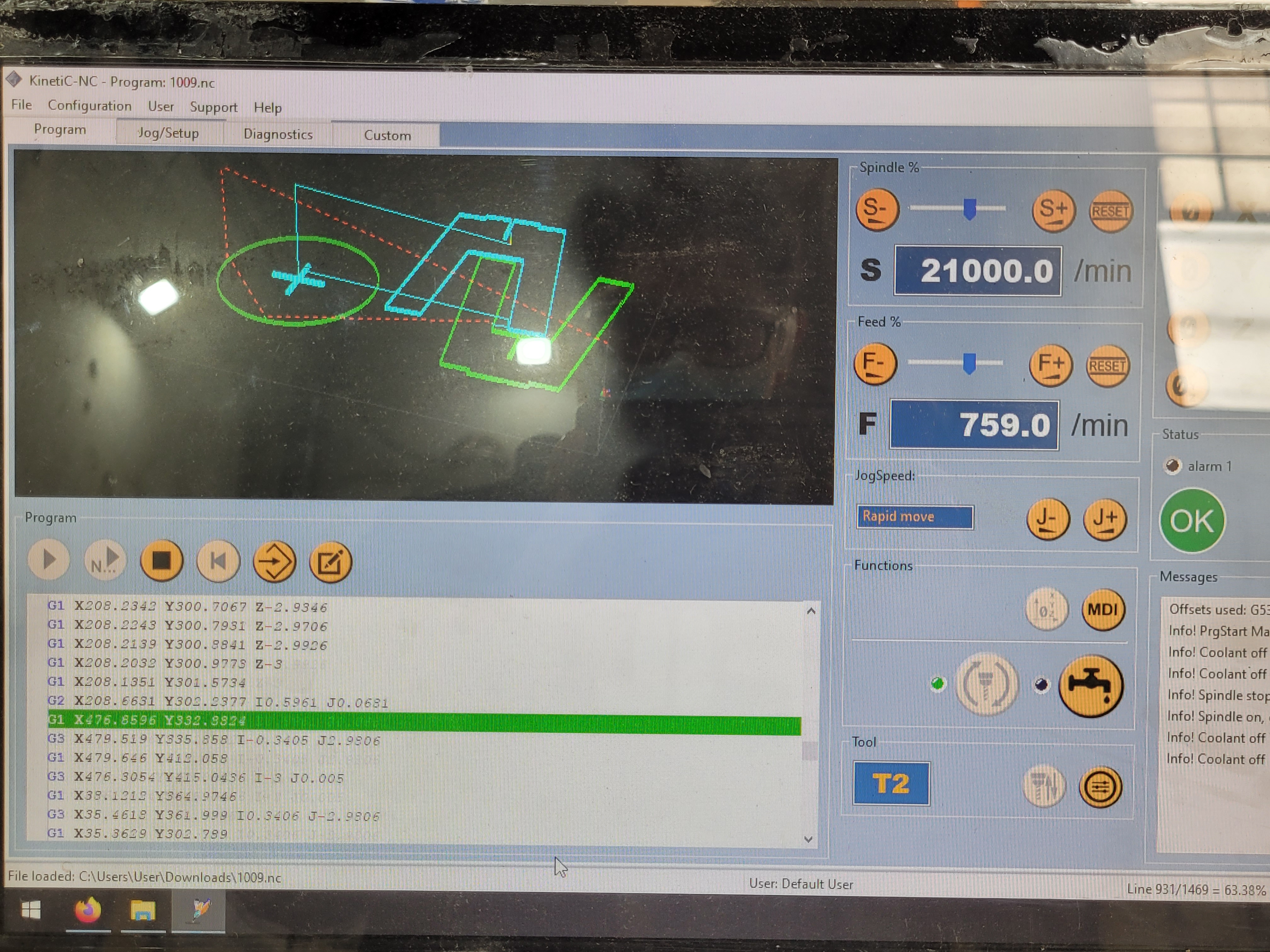
 Nevertheless, we tested in the machine if it cutted or not with drill operation because this one made more simple movement for the screw. Happily, it worked! :)
Please do not forget to follow the safety guidelines before using the machine. You can find it in our group documentation
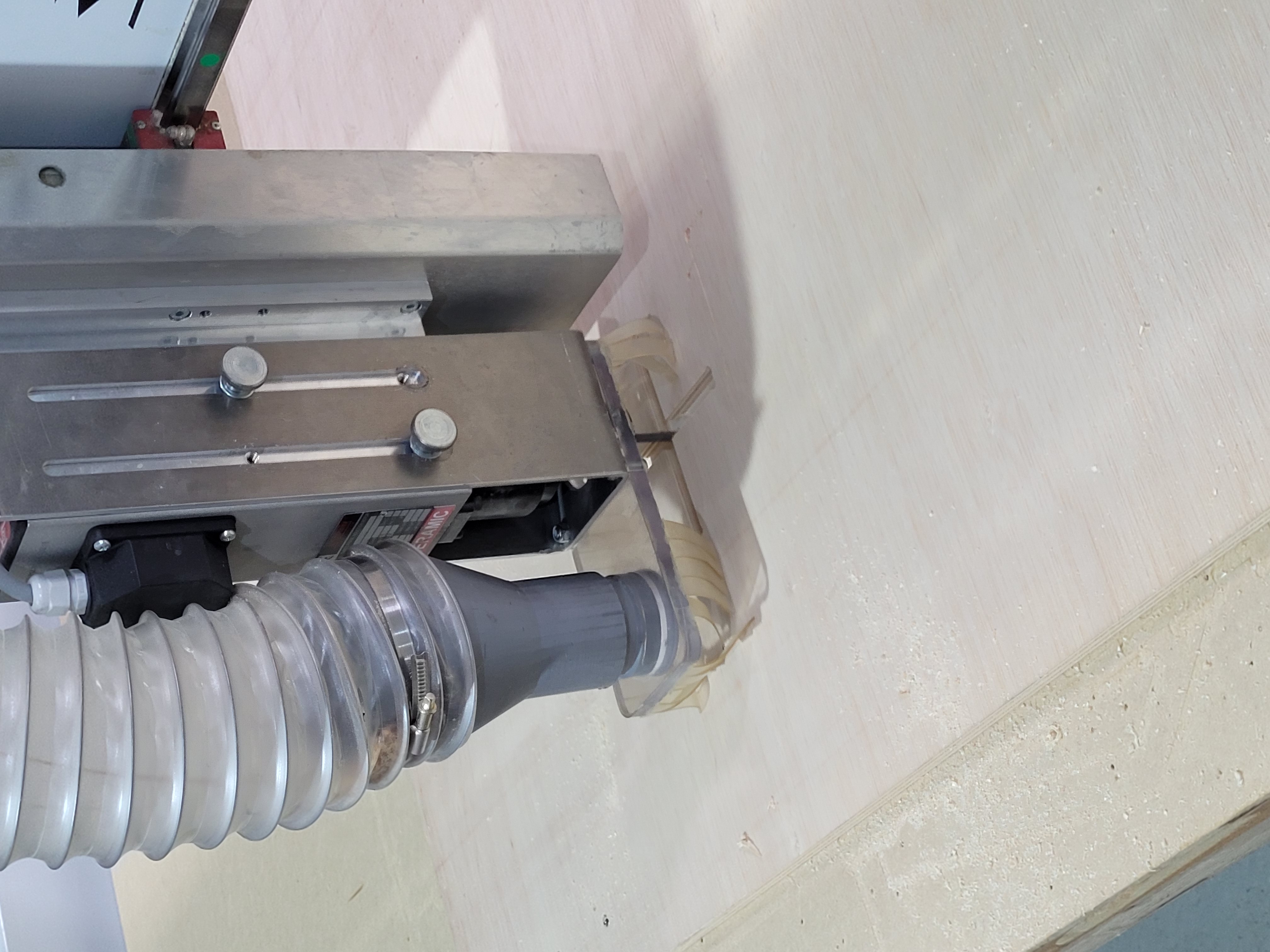
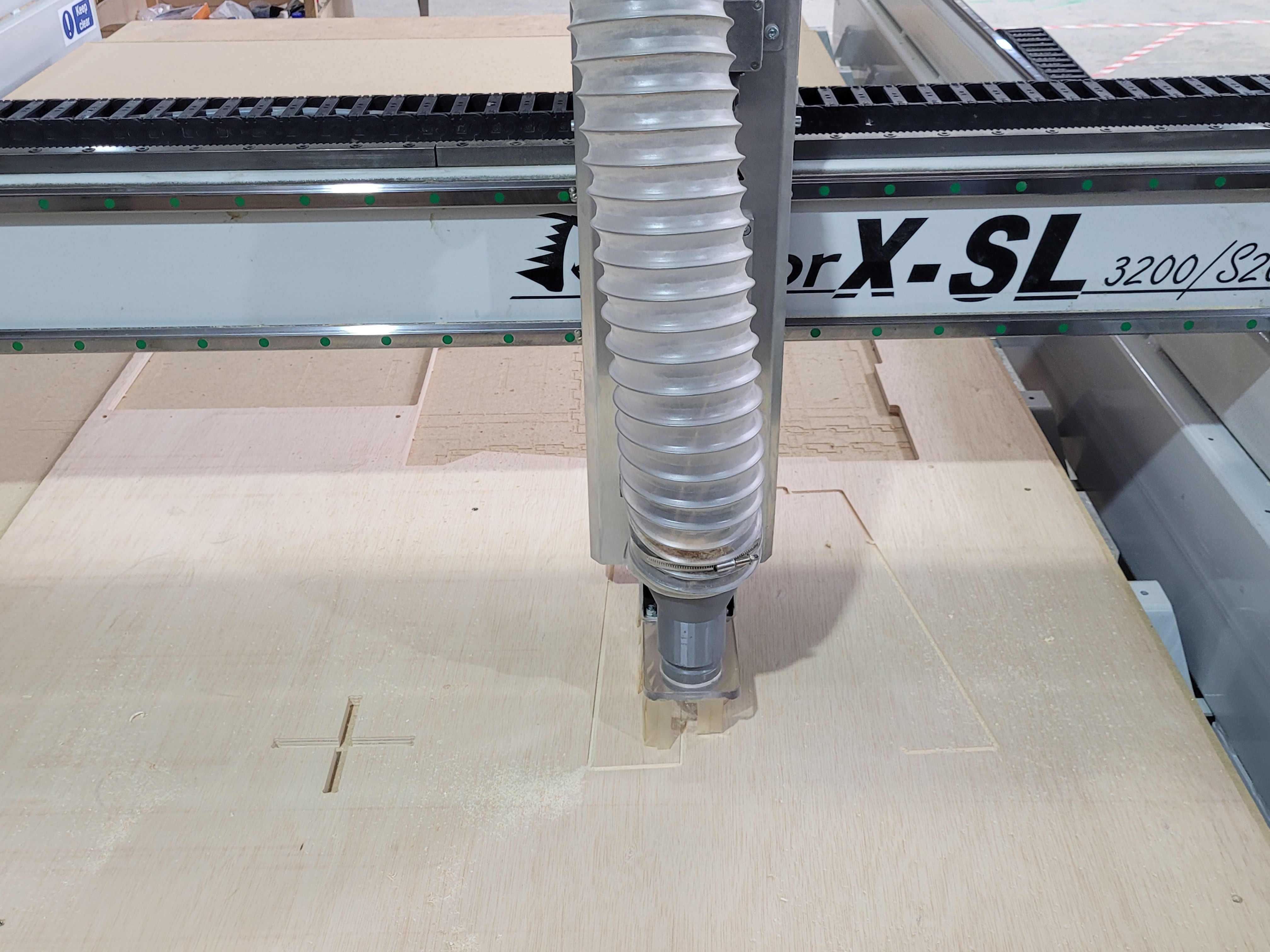
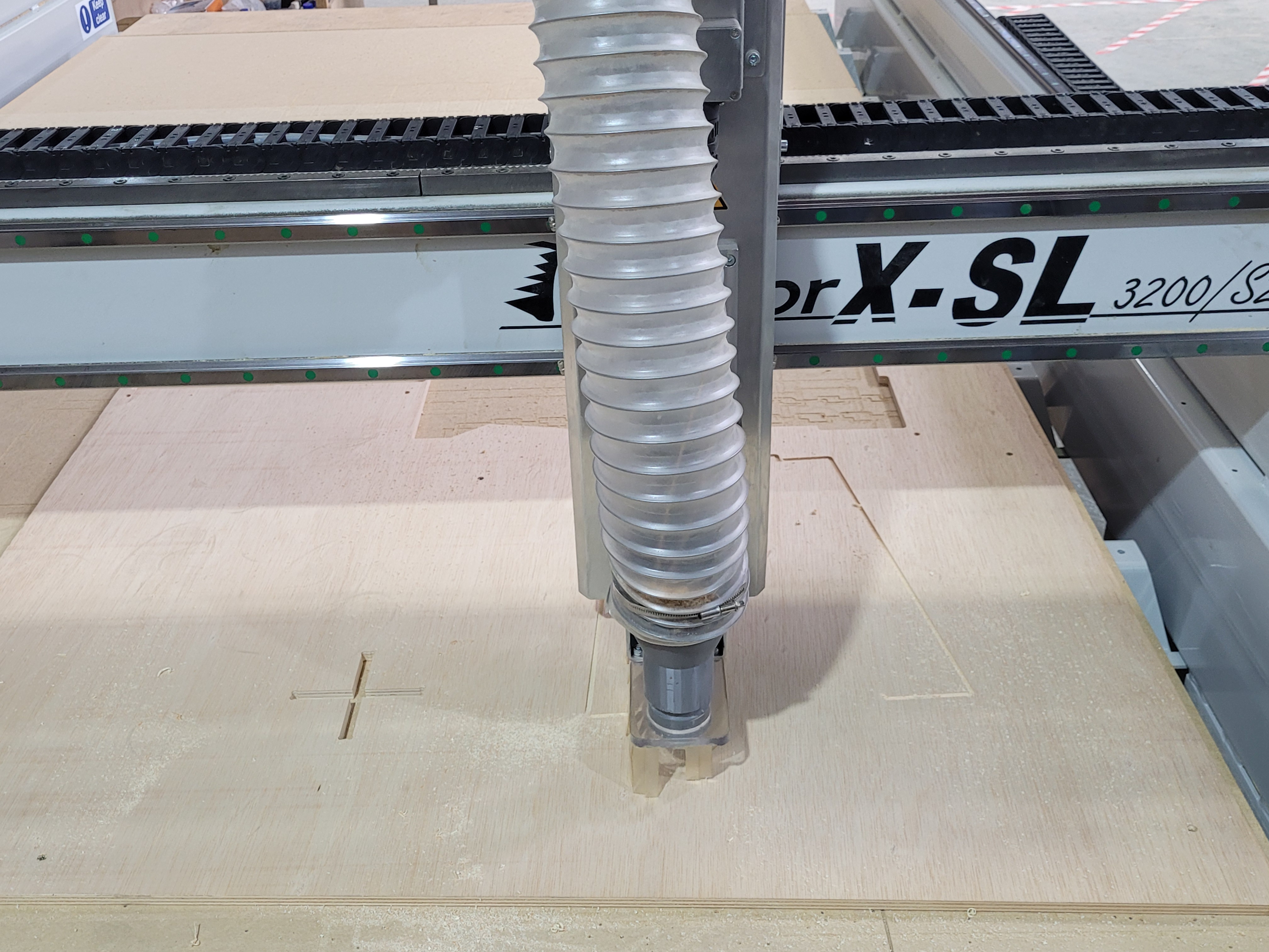
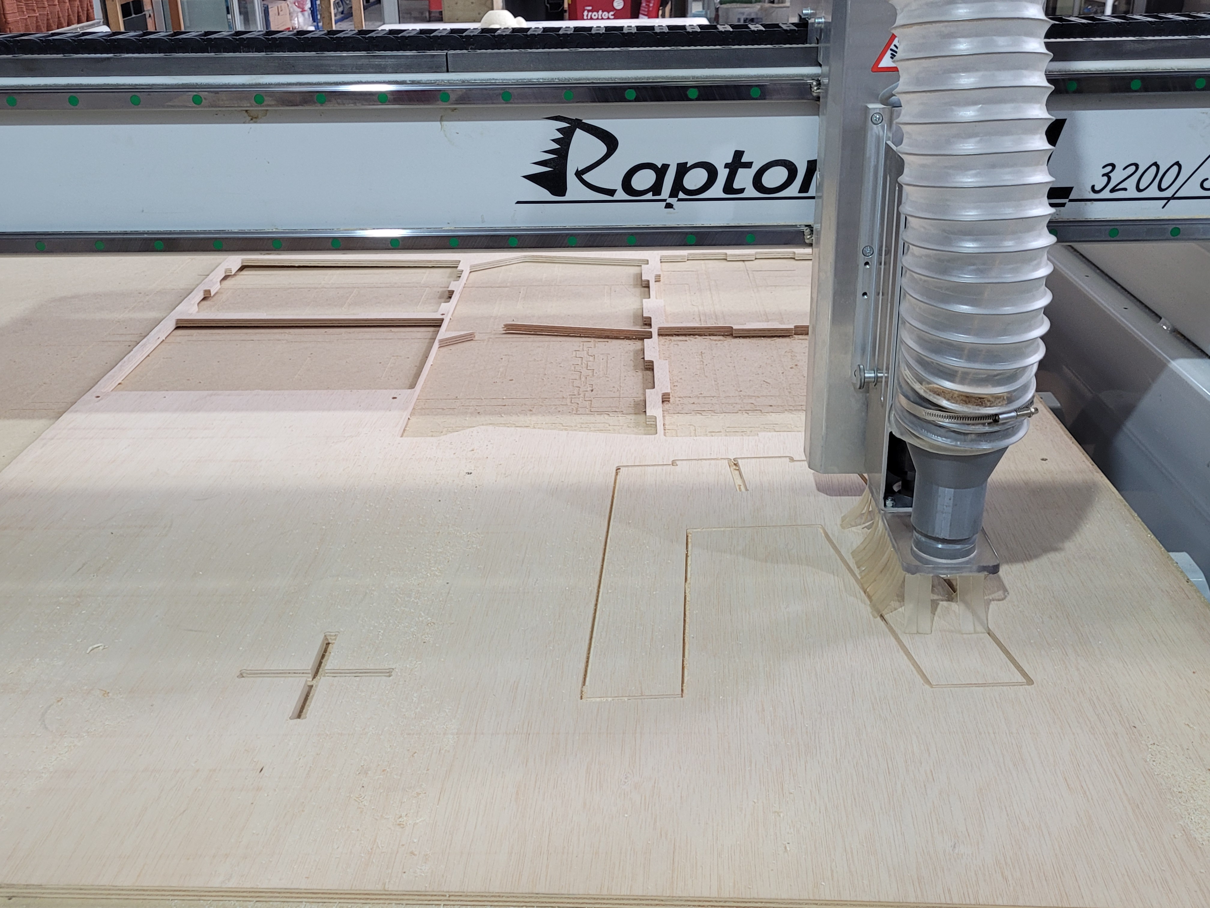
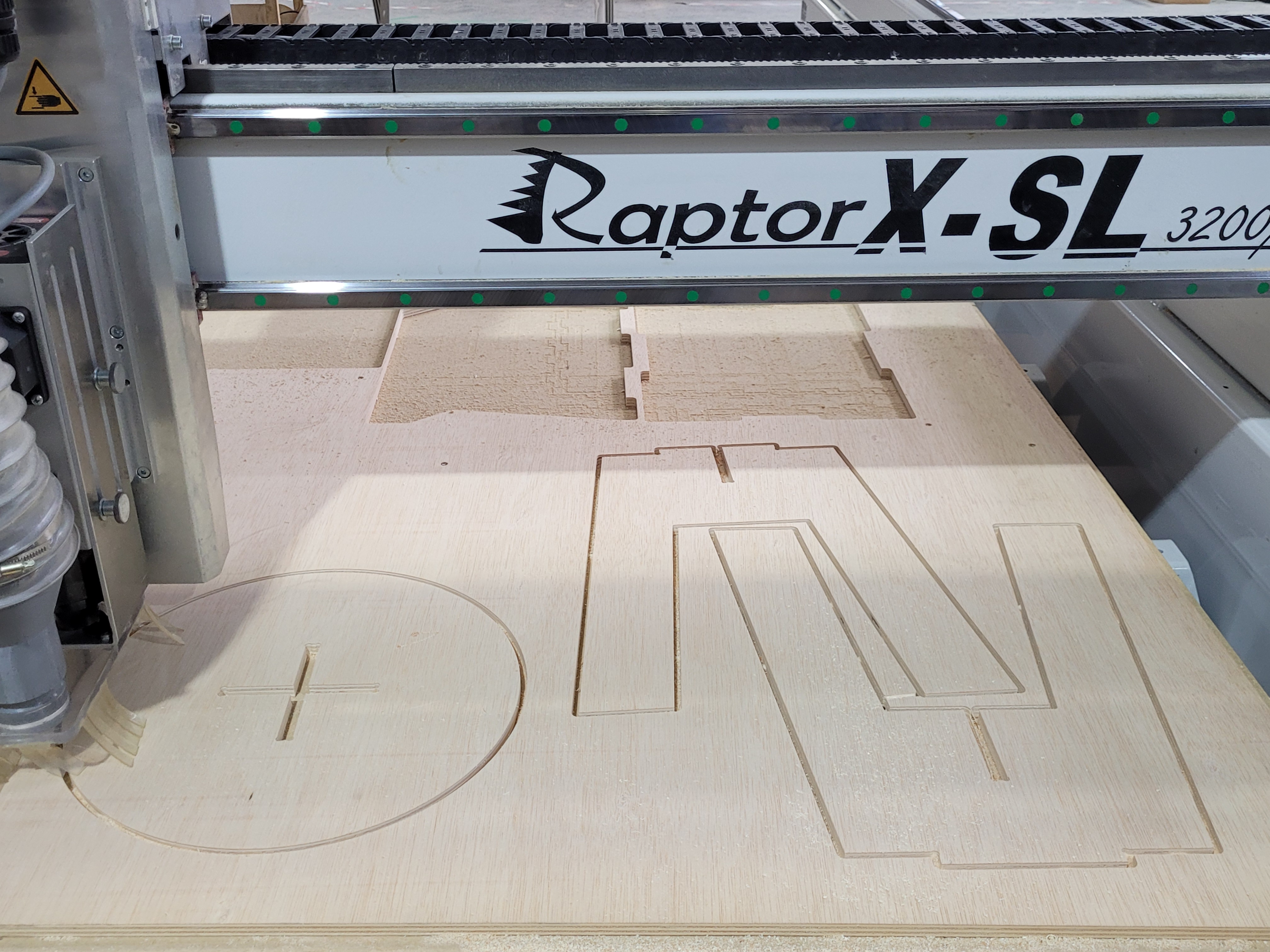
Here there some pictures of the cutting process.
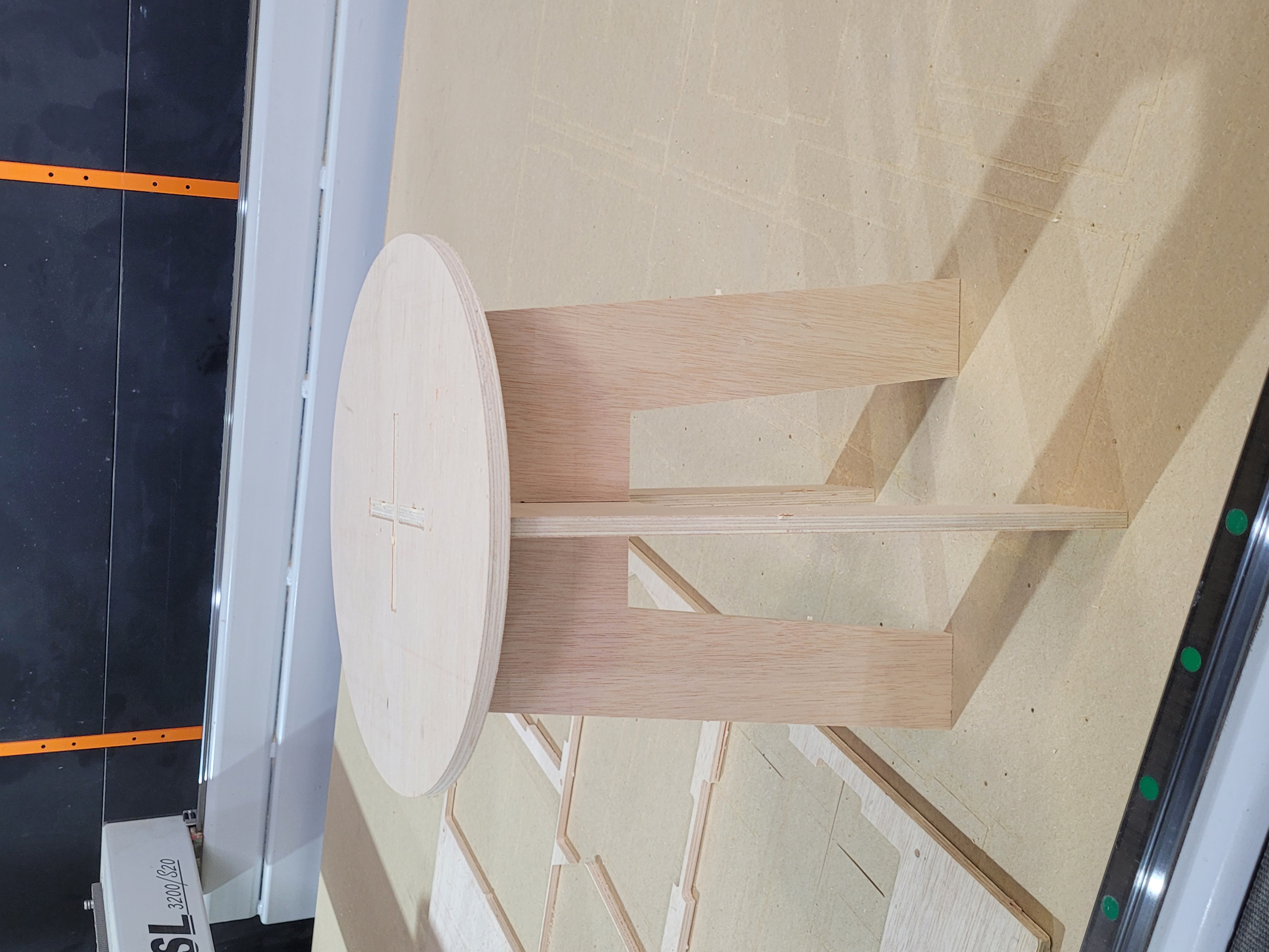
This is the final result:
Group Assignment
Here is the link.