Final Project
For my final project I am going to desing a wireless Door Sensor that triggers a notification to the smartphone and sends an email to the police or other people. I decided to do this project because when many people take vacations they may stay abroad for many days or even weeks and it can be a good solution for their peace and safety having this device.
Electronics
To design my board I was looking for some information because as we have learned during the program, the most important part in each board is the microcontroller, therefore I have to decide which microcontroller use and define what kind of sensor I am goint to use (I had three option: PIR Sensor, Reed Switch sensor, hall sensor). I found the following references:
- To follow a workflow, the Help button of Jimena Galvez Paredes will be very useful and has many tips for using WiFi and Bluetooth connectivity.
- To get a good explanation related to how to connect the microcontroller by wifi and bluetooth, this is the
Indispensable Pill Case of Griffin Van horne. - And the last reference but not less important and even I can say that is the mos important because I am going to based my design on this previous work, called Barduino, made here at Fablab Barcelona by Eduardo, Joseph and Oscar.
All these references have in common that they used a ESP32 as microcontroller. This little guy is amazing and while I am learning more about this MCU, I feel surprised for all the things that allows us to do; for example: It can connected by bluetooth and wifi with other devices. So, I chose this MCU.
ESP32 microcontroller
We have learned that the first thing that we have to do is read the datasheet. So, you can find the datasheet fo the ESP32-WROOM-DA in this link. It is important to mention that in the previous versions they used a ESP32-WROOM-32D which have physical differences comparing with the ESP32-WROOM-DA. Here there are two pictures of some features of the ESP32-WROOM-DA.
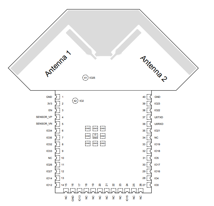
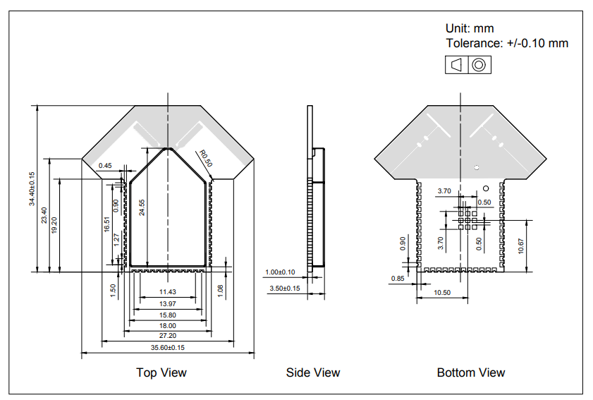
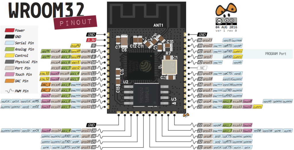
Here you can see the ESP32-WROOM Pinout:
Designing the main board
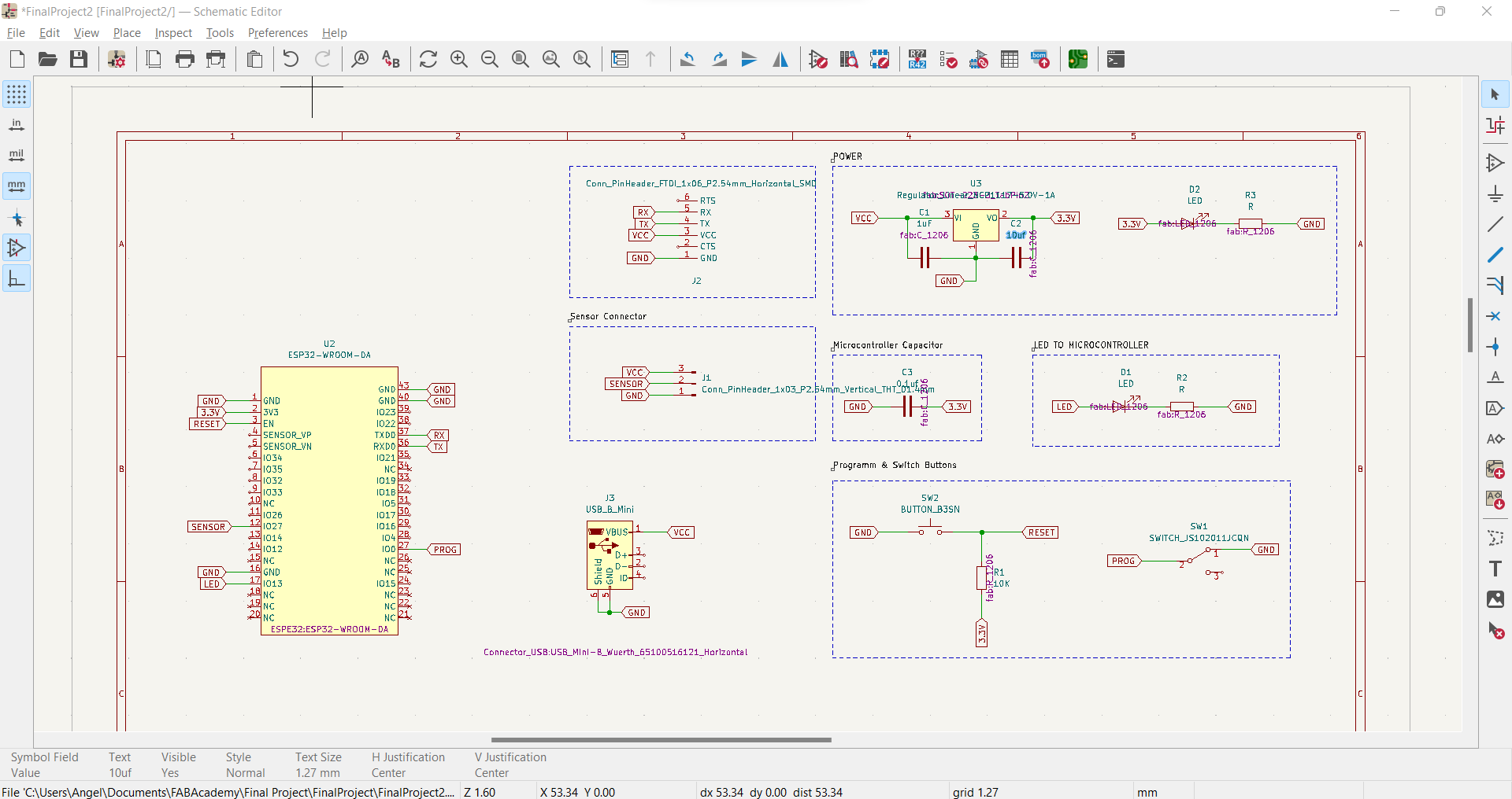
So, I did the schematic on Kicad and to do it I analized with to much detail the Barduino to see all the components and why I had to add other components. So, I chose the following componets:
- 1 Voltage regulator (3.3v) with two capacitor (1uF)
- 1 Pin 01x06 connector that will help us to make the connection to program the board
- 1 LED that shows us if the connection to the computer is right or wrong with 1 resistor (100Ω)
- 1 Pin 01x03 to connect the hall sensor
- 1 capacitor for the microcontroller
- 1 LED to the microcontroller that can be programmed that will work as a output. Also, with 1 resistor (100Ω)
- 1 button connected to the microcontroller to be protect and it needs a pull-up resistor (1KΩ) to protect it from little currents or bouncing.
- 1 Mini USB connector for durability and power
- 1 Switch Slide SPDT
- ESP32-WROOM-DA microcontroller
My instructor helped me with the footprint and the symbol of the microcontroller because there was not in the fab library that we downloaded in the week 6
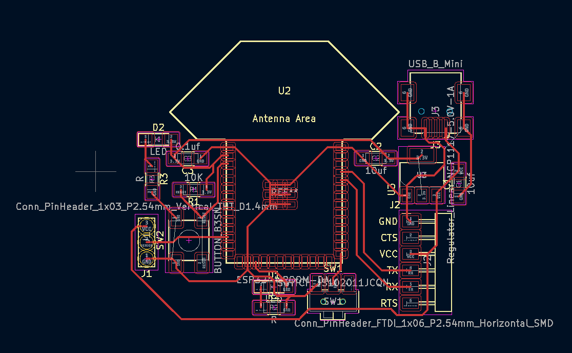
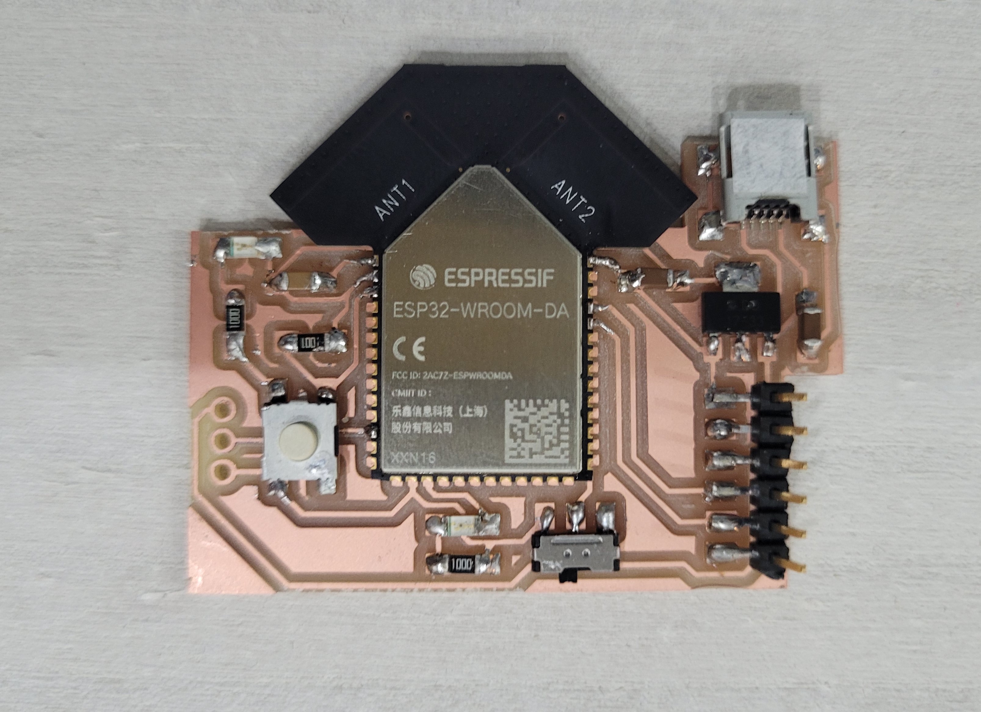
This is the final result:
Next step, routing the board was challenge because I had more components and also it was better to design a smaller board. Besides, I decided that the two antennas were outside the board to have a good quality of signal when we do the wi-fi connection. After working for all the afternoon, this was the final result:
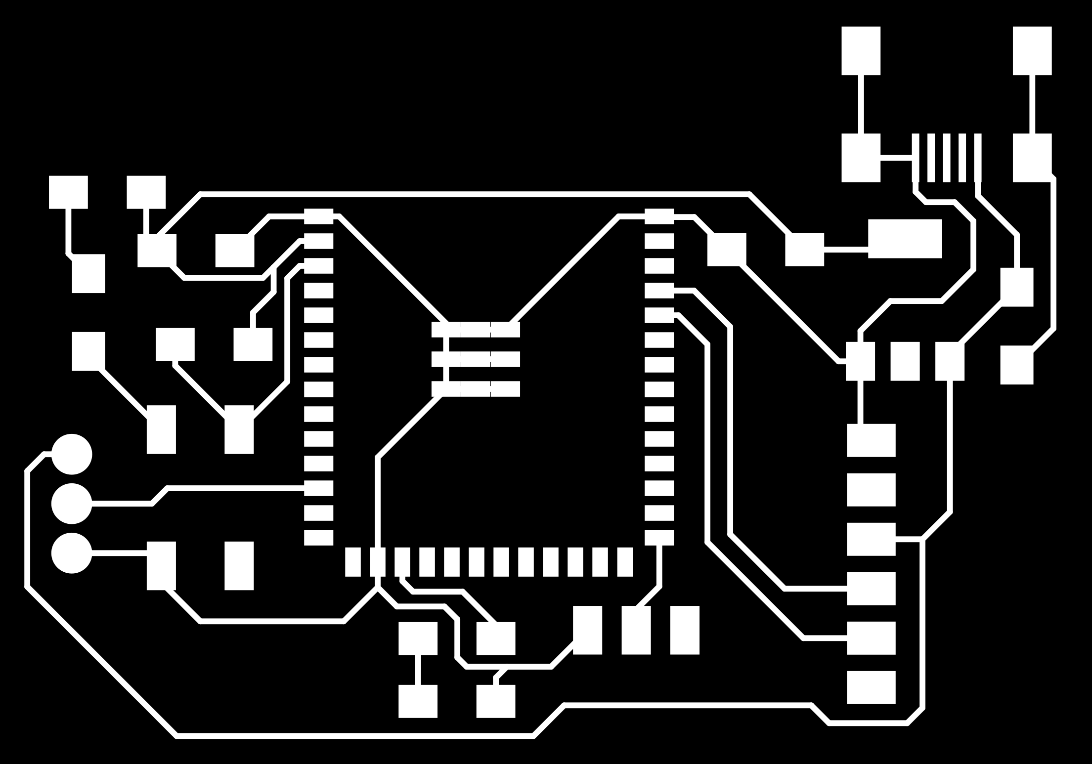
So, once I had the svg file I went to Inkscape and I did something new here because I create a holes for the hall sensor, USB mini and the switch slide. Now, I can get the png Files:


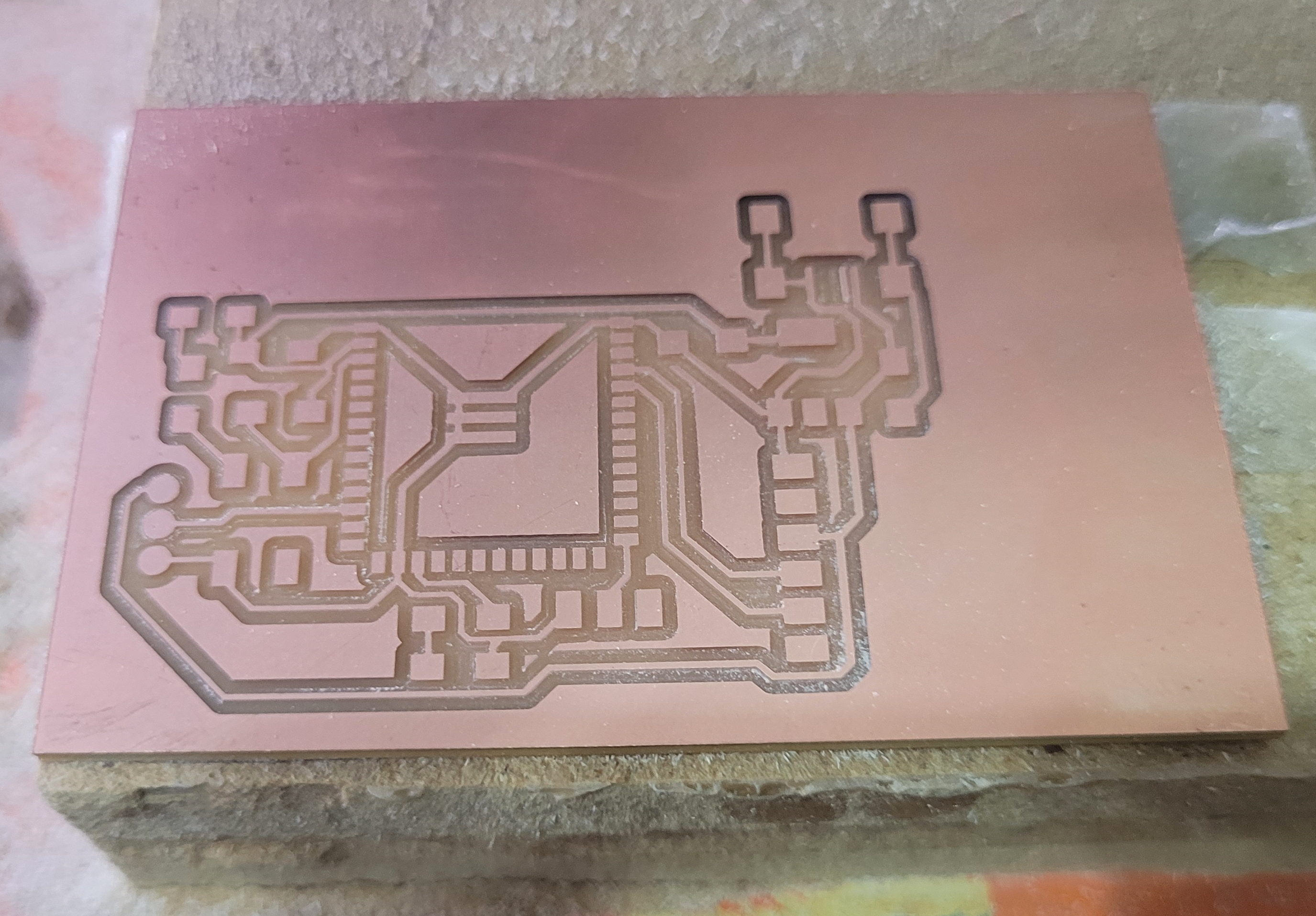
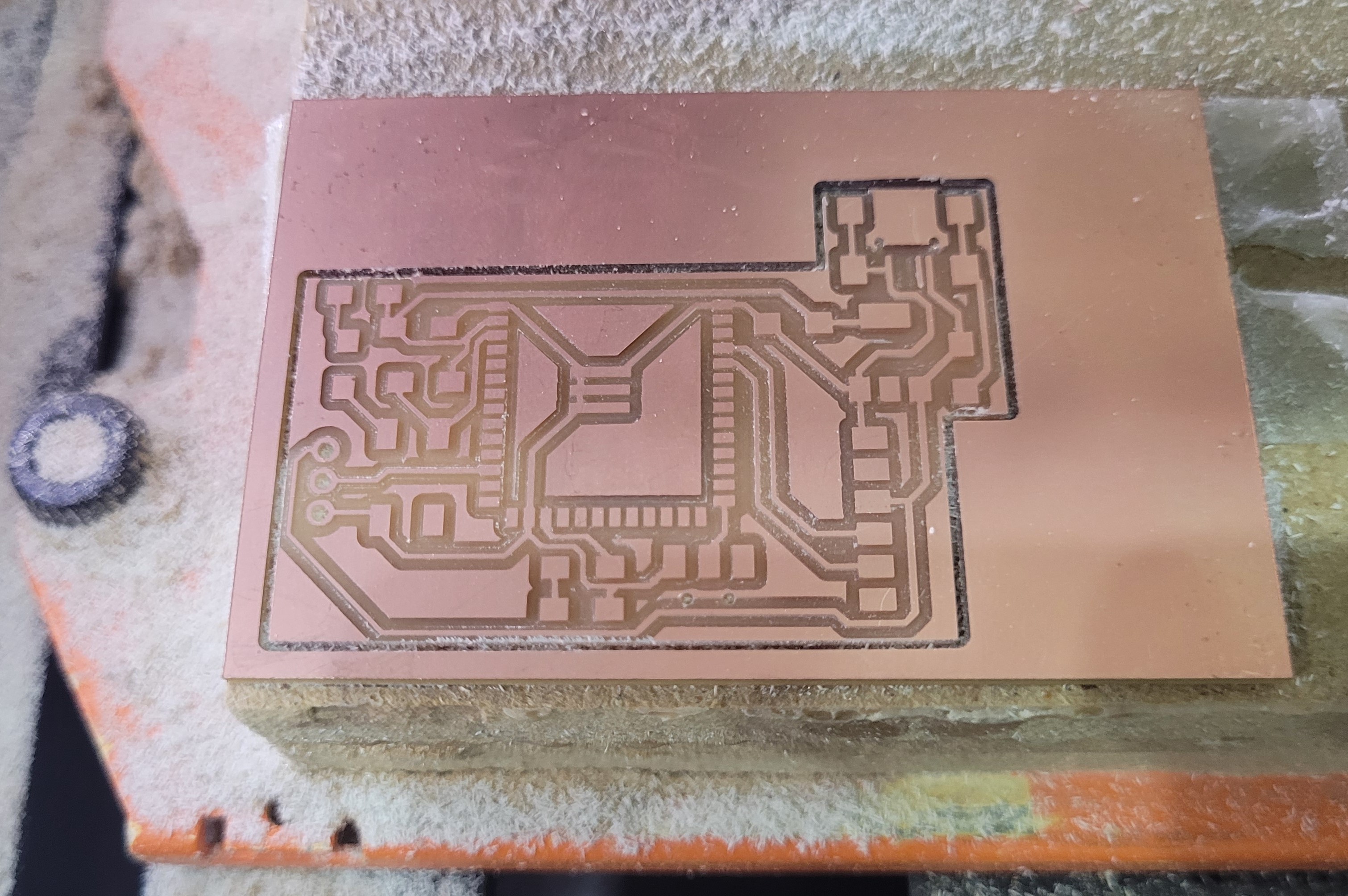
 And as we know we can go to the milling machine with our file generated on modsproject. Here, you can see some images of the process:
MillingESP32Board from Angel Erazo on Vimeo.
Now, time to solder and I was not too difficult stuffed the ESP32. Here you can see the final result:
Designing the hall sensor
As I mentioned I had to choose what sensor will work better for my project. I had three options and my instructor recommended me to use the hall sensor and solder to the main board. So, I worked with the hall sensor.
To design this hall sensor I had to check in the inventory of the Fablab the code and I used the Sensor Hall Effect Analog SOT23W (A1301KLHLT-T) and the datasheet is here. Reading the datasheet I realized that this sensor works with a voltage between 4.5v to 5v but my board works with 3.3v, so I needed to convert the 5v sensor signal to 3.3v digital input. To do that, I added one resistor (2K Ohmio) and (1k Ohmio). The schematic for this circuit is:
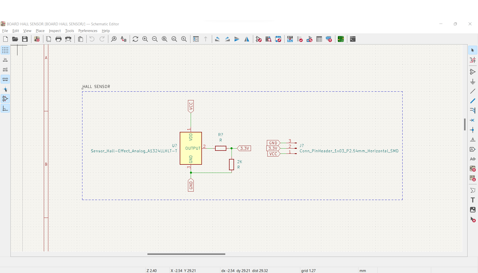
Definitely, the phrase that I am going to remember forever “Check the datasheet” This is the result of routing this little board:
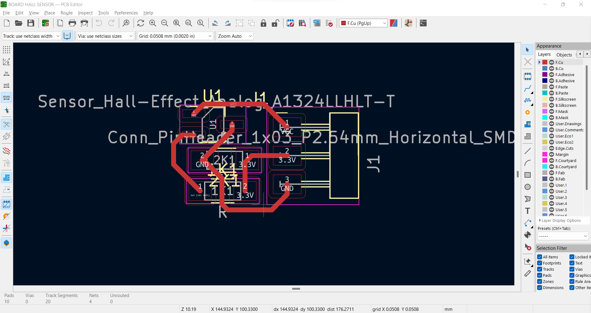
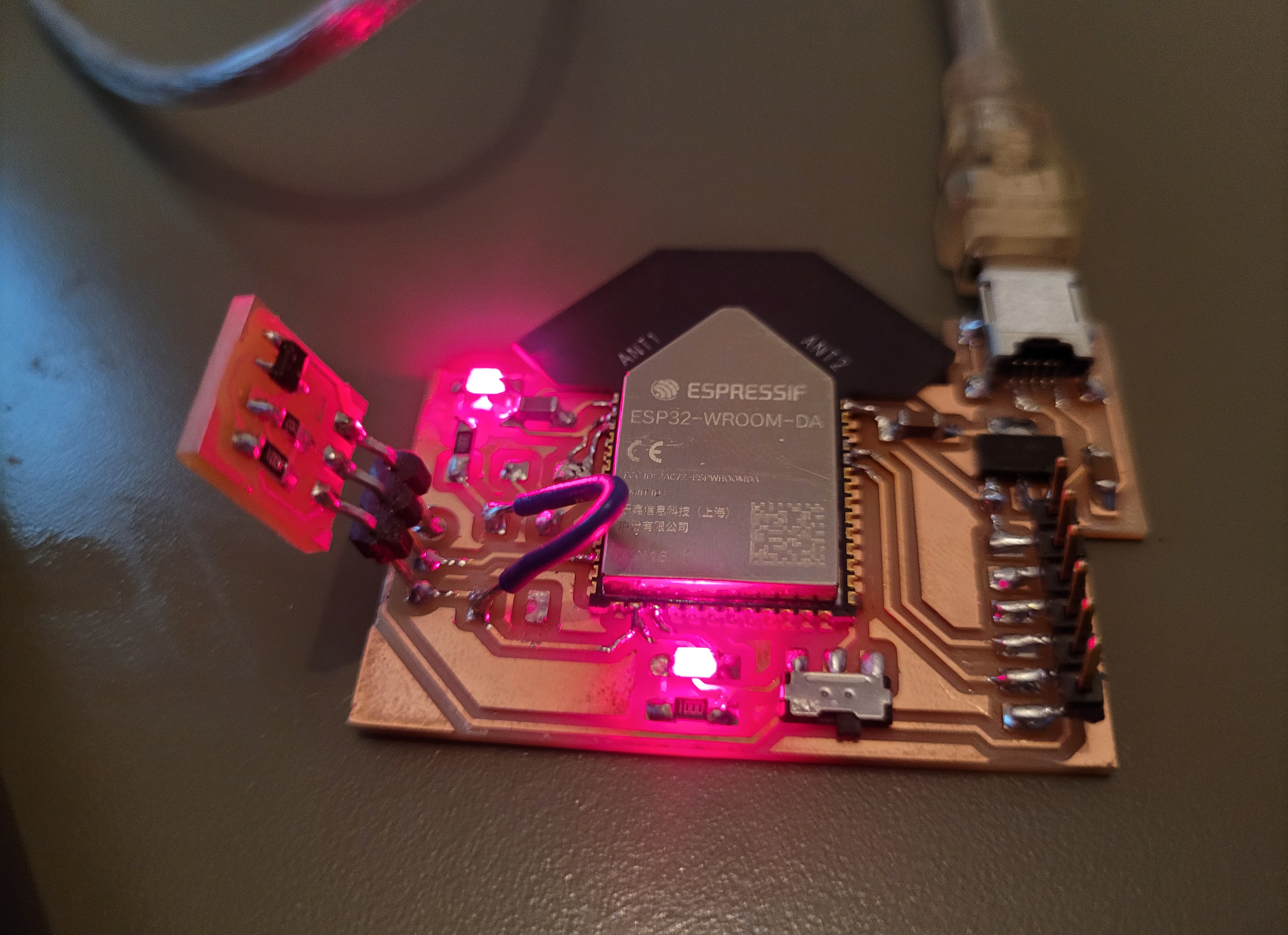
As Final step the two boards were soldered to work as one.
The integrate board looks well, something to improve is to join the hall sensor in only one board.
Code
In this part I need to add in my code the wireless capabilities that allows me to send an email and also to turn the led on when the door is open. Another thing to take in consideration is what kind of email notificacions will be used because it caused to create a different code and to do other steps.
So, for the email notifications I can find two types: SMTP server and IFTTT. I did not have any preferences and I choose IFTTT because that platform allows me to control dozens of products and apps, it seems a powerful platform that I am going to use after Fab Academy.
Using IFTTT as email notifications
I had to create an IFTTT acount. I went to the official site. This is the link. To create an account I follow the next steps:
- Enter to this link
- Go to Add button
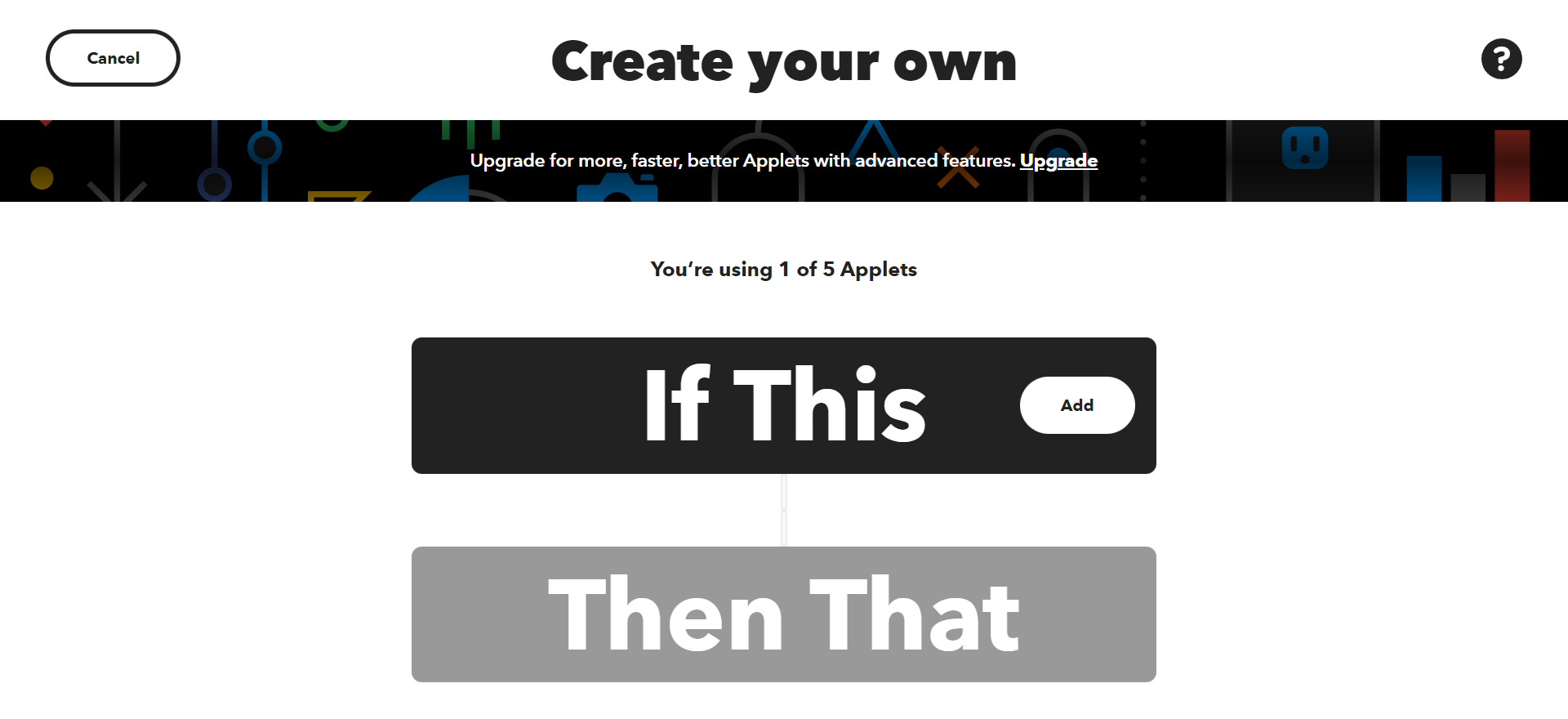
- On the search bar type webhooks
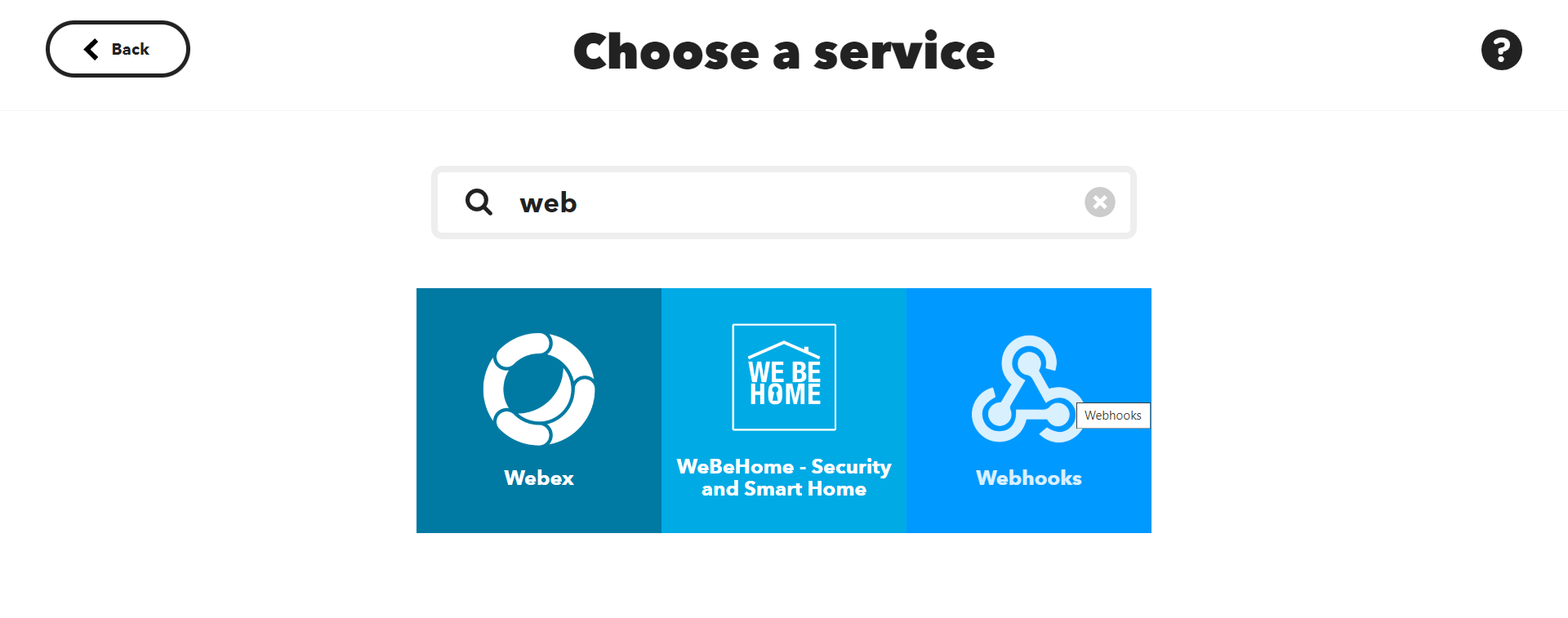
- Select “Receive a web request”
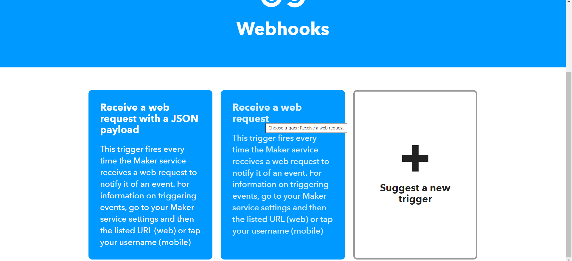
- Create a name for the event

- Click on the botton Add
- Search “email” and choose the option “email”
- Click on send me an email
- Then, we have to write the email subject and body
- Click on “continue”
- Finally, Click on finish
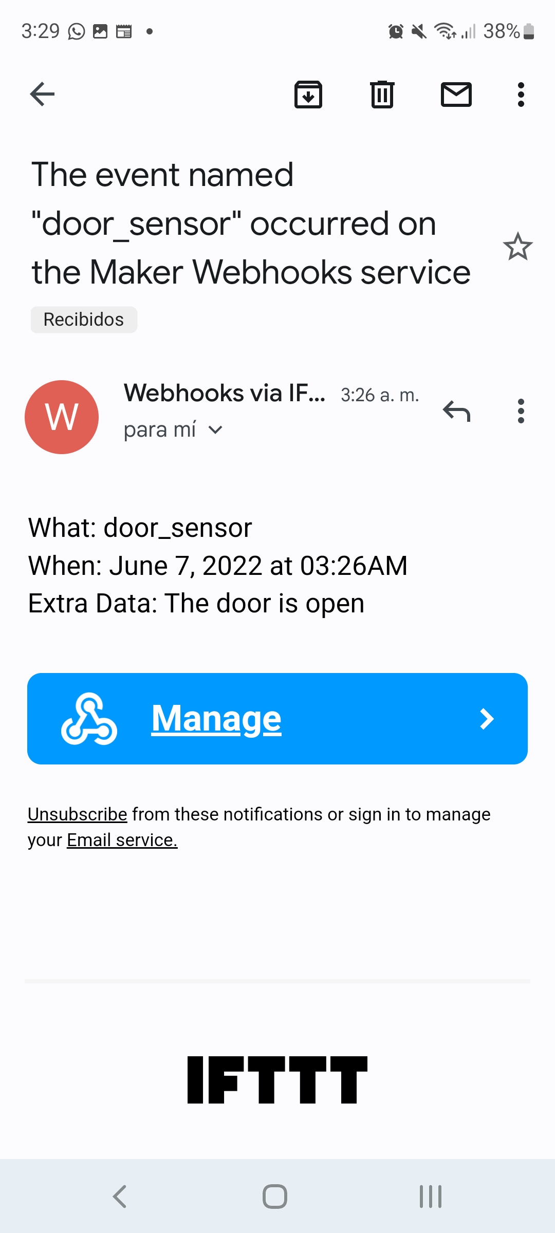
Then when you want to do a test you can get an email, I have recived this one:
Testing the hall sensor with ESP32
I decided to do a test to see how the hall sensor works with the ESP32 and to get use to with this microcontroller. I used the following components:
- ESP32
- Breadboard
- Hall sensor
- Lead and resistor
- Wires
- Magnets
I tested this code:
int sensor = 27;
void setup() {
  // initialize digital pin LED_BUILTIN as an output.
  Serial.begin(9600);
  pinMode(13, OUTPUT);
  pinMode(sensor, INPUT);
}

// the loop function runs over and over again forever
void loop() {
  int lectura = analogRead(sensor);
  if ((lectura < 1800) || (lectura > 2100)){
    digitalWrite(13, HIGH);
  }
  else {
     digitalWrite(13, LOW);
  }
  Serial.println(analogRead(sensor));
  delay(100);
}
This is a video of the testing:
Testing from Angel Erazo on Vimeo.
As you can see the hall sensor was a good decision for my project. After this I worked on the code for sending the email.
Final Code: Hall sensor + Wifi + Sending the email
For this code I added the library of wifi and I want to send a notification email to a person or to the police. The next step is to connect the ESP32 to a IFTTT. Also, when the door is open the Led must turn on. This the final code:
#include <WiFi.h>

int sensor = 32;

unsigned long previousMillis = 0;
const long interval = 1500;

const char* ssid = "Iaac-Wifi";
const char* password = "EnterIaac22@";
const char* host = "maker.ifttt.com";
const char* apiKey = "fM6cXYr9NICYM9v31SQ7_NH1230HqzuvWTvZVG24Kl3";

bool sended = false;


void setup() {
  // initialize digital pin LED_BUILTIN as an output.
  Serial.begin(9600);
  pinMode(13, OUTPUT);
  // Connect to Wi-Fi
  WiFi.begin(ssid, password);
  while (WiFi.status() != WL_CONNECTED) {
    delay(500);
    Serial.print(".");
  }
  Serial.println("");
  Serial.println("WiFi connected");
  pinMode(sensor, INPUT);
}

void loop() {
  int lectura = analogRead(sensor);
  if ((lectura < 1800) || (lectura > 2100)) {
    digitalWrite(13, LOW);
    if (sended == false) {
      sendEmail();
      sended = true;
    }
  }
  else {
    sended = false;
    digitalWrite(13, HIGH);
  }
  Serial.println(analogRead(sensor));
  delay(100);
}

void sendEmail(){
  //Send email
  Serial.print("connecting to ");
  Serial.println(host);
  WiFiClient client;
  const int httpPort = 80;
  if (!client.connect(host, httpPort)) {
    Serial.println("connection failed");
    return;
  }

  String url = "/trigger/door_sensor/with/key/";
  url += apiKey;

  Serial.print("Requesting URL: ");
  Serial.println(url);
  client.print(String("POST ") + url + " HTTP/1.1\r\n" +
               "Host: " + host + "\r\n" +
               "Content-Type: application/x-www-form-urlencoded\r\n" +
               "Content-Length: 13\r\n\r\n" +
               "value1=" + "The door is open" + "\r\n");
  }
In the first part I added the wifi library and define the ssid and password of the wifi connection. In the setup part, the ESP32 connects to the WiFi network, so it is ready to receive data and send the email notification. Also I defined the hall sensor as Input and the Led as output. In the loop part, here we have all the actions in a period of time, the led turns on when the door is open and at the same time is sending a email.
Case
3D Printing
I printed one case for my board with the following dimensions: 59.50mm x 72.04mm x 45.01mmm
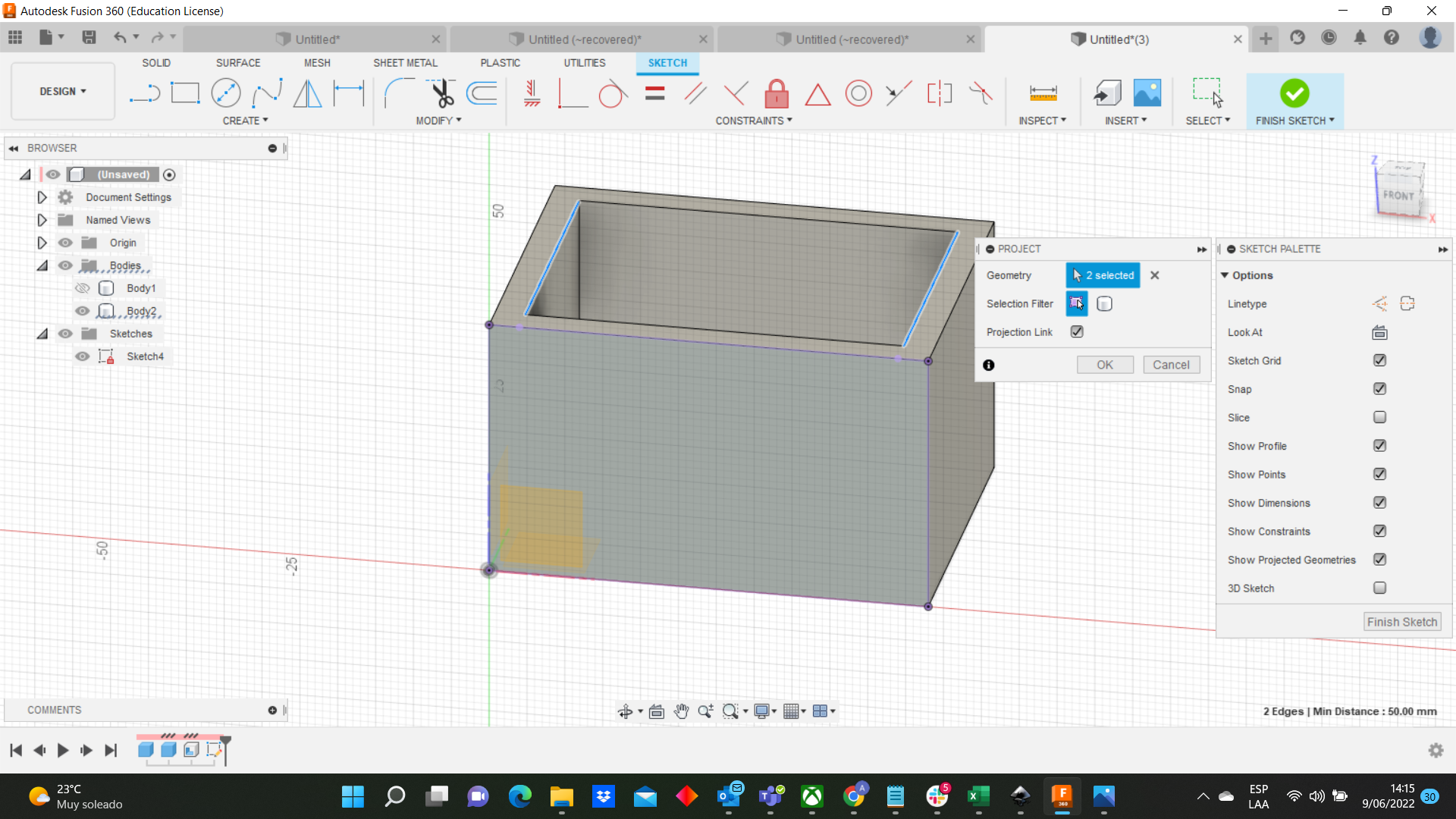
- I used fusion for my case and I started with a rectangle then I used the extrude command and I got a solid.
- I used the section analysis command to open the solid with a thickness in the sides.
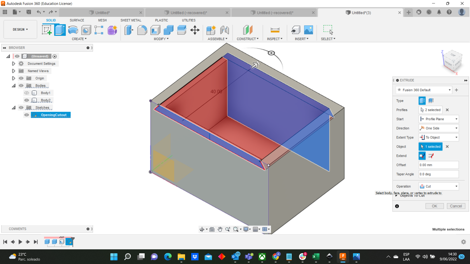
- Then, In the front side I sketched a rectangle to use the extrude command to get the space for putting the lid
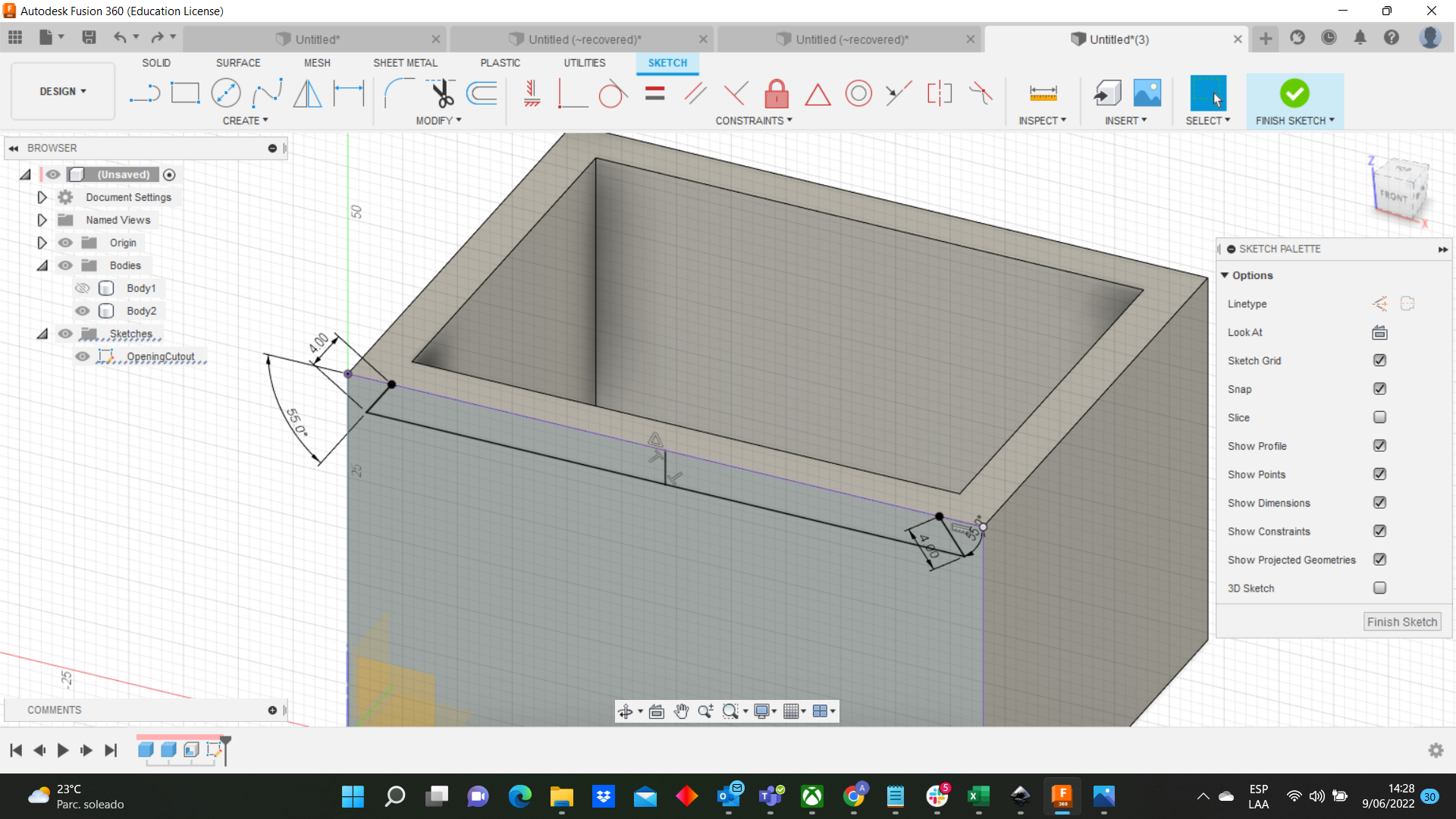
- Afterwards, I designed on the sides the rectangles for the screw.
 With my file I went to the 3D printers. I have images and 1 video of the process:
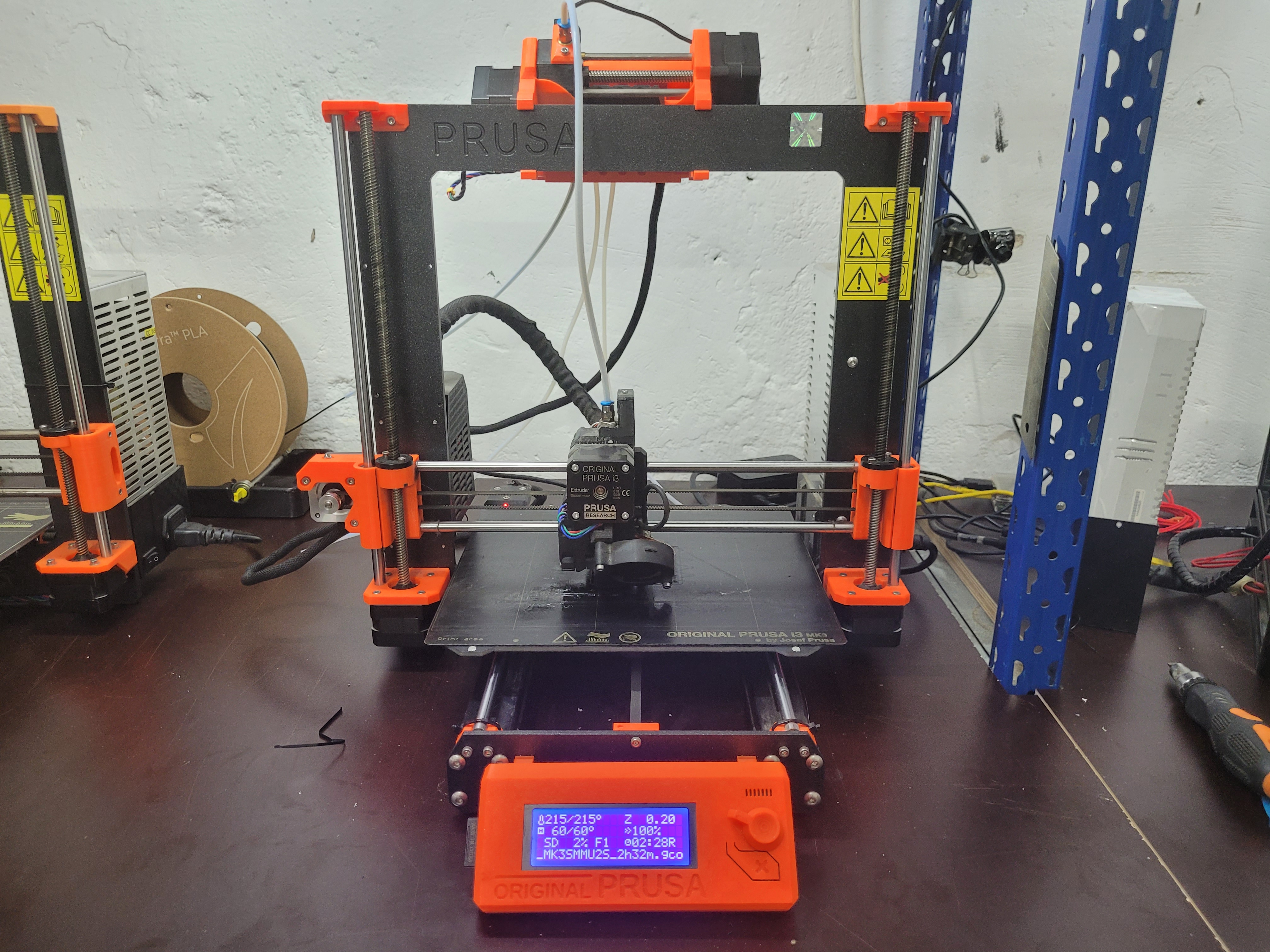
Final-3DPrinting from Angel Erazo on Vimeo.
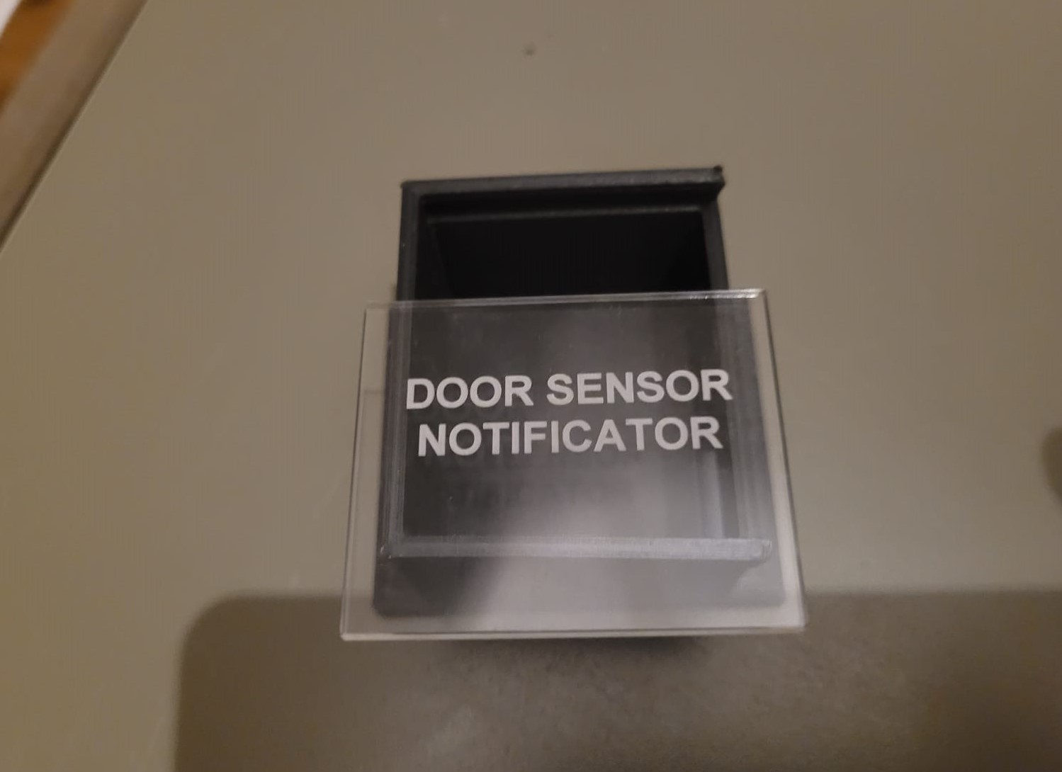
Laser Cut
Also, I used a lid for the case with the following dimensions:
58mm x 47mm
I added to the lid an engrave
 I have a video of the process:
Final-LaserCut from Angel Erazo on Vimeo.
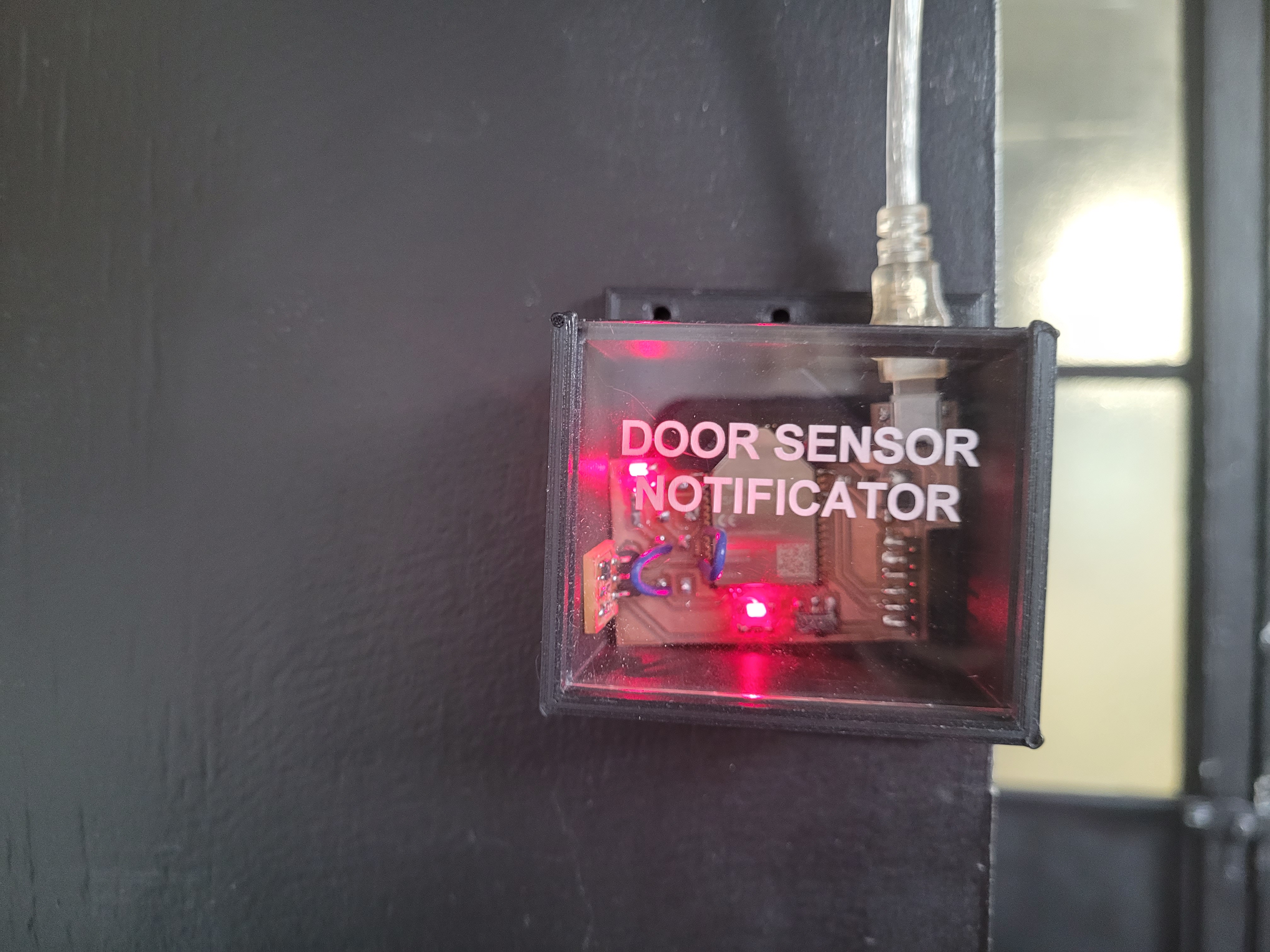
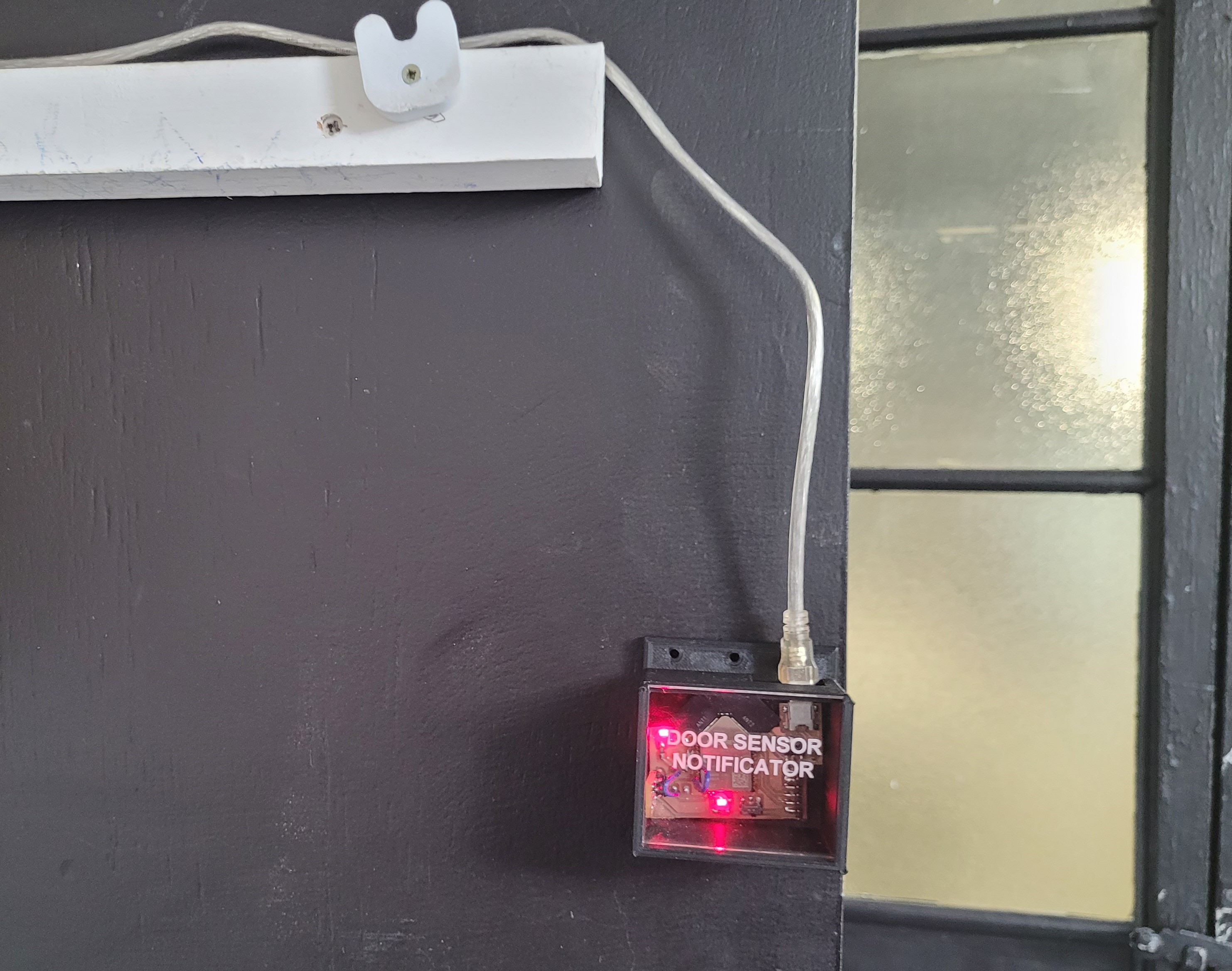
Final Project
I joined all the parts and this is the final result:
FinalResultt from Angel Erazo on Vimeo.

presentacion from Angel Erazo on Vimeo.