5. Electronics production
Individual Assignment
This is the first week of electronics and I would like to learn as much as possible. The assigment is to mill, stuff with components and program a board. This board will be used to program the other boards we will create in the rest of the course.
Boards
First of all, we had to choose the boards. We have a Programmers Collection in the Fabcloud and then we had to download the files of the following programmers:
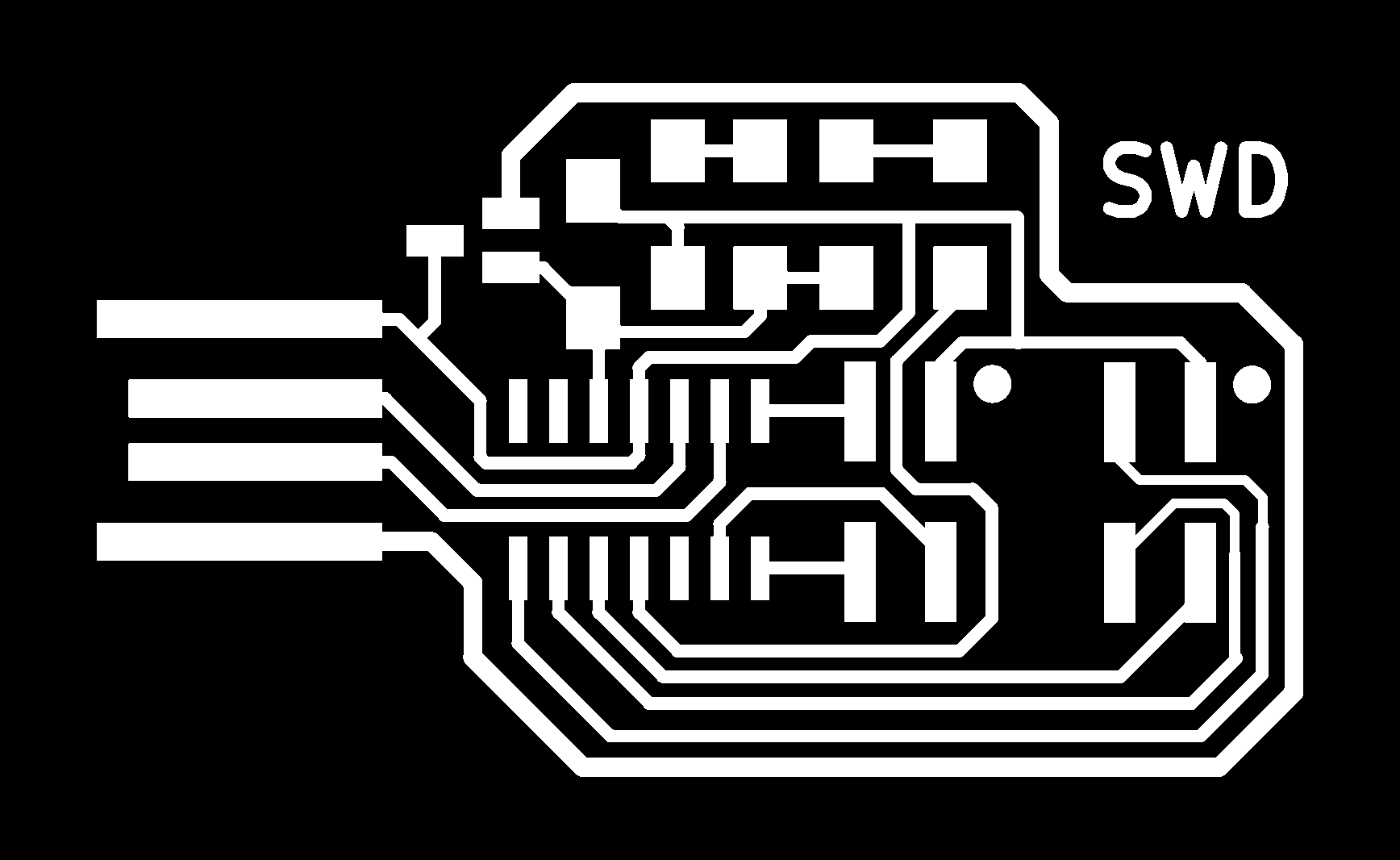
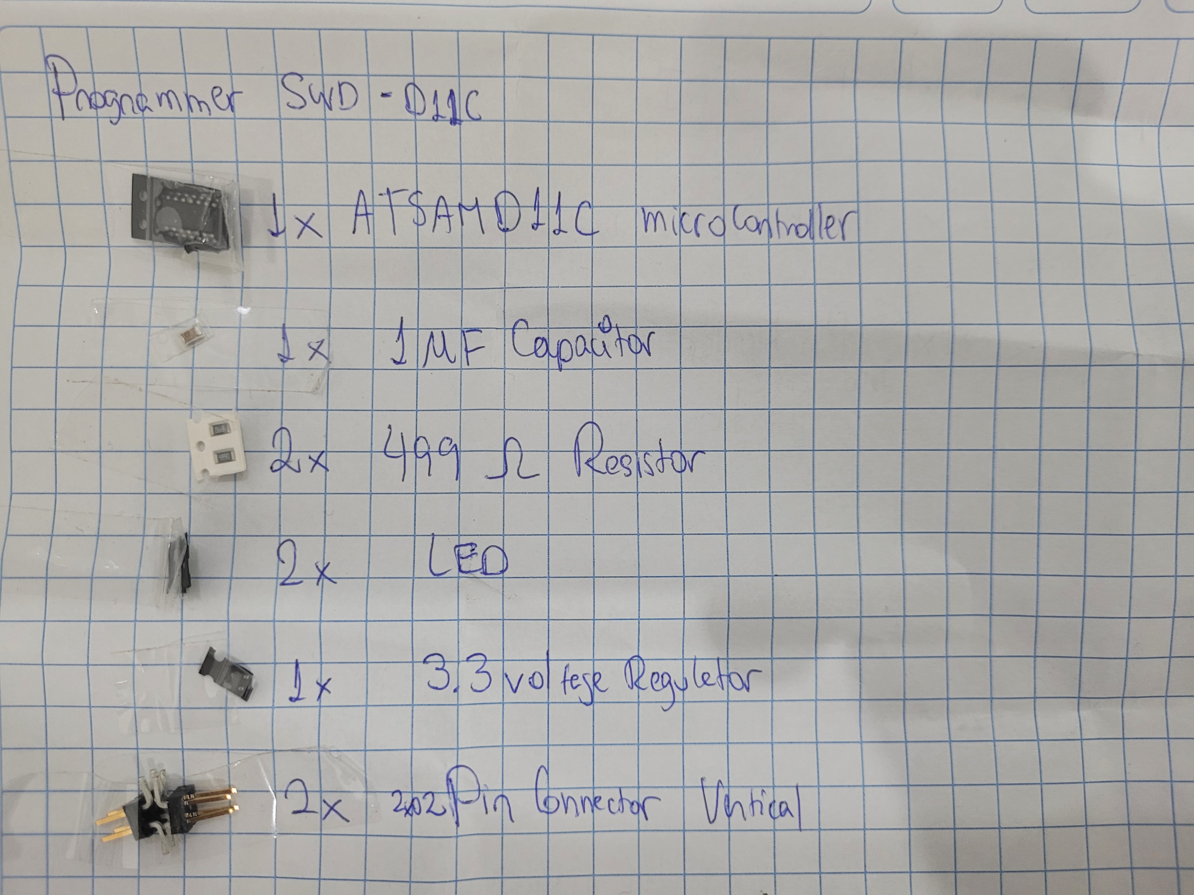
1.- Programmer SWD D11C
- It allows us to program the other MCU for the next weeks.
- Something that we have to keeping in mind is to programm this master board we need another program from the Fab Academy instructors.

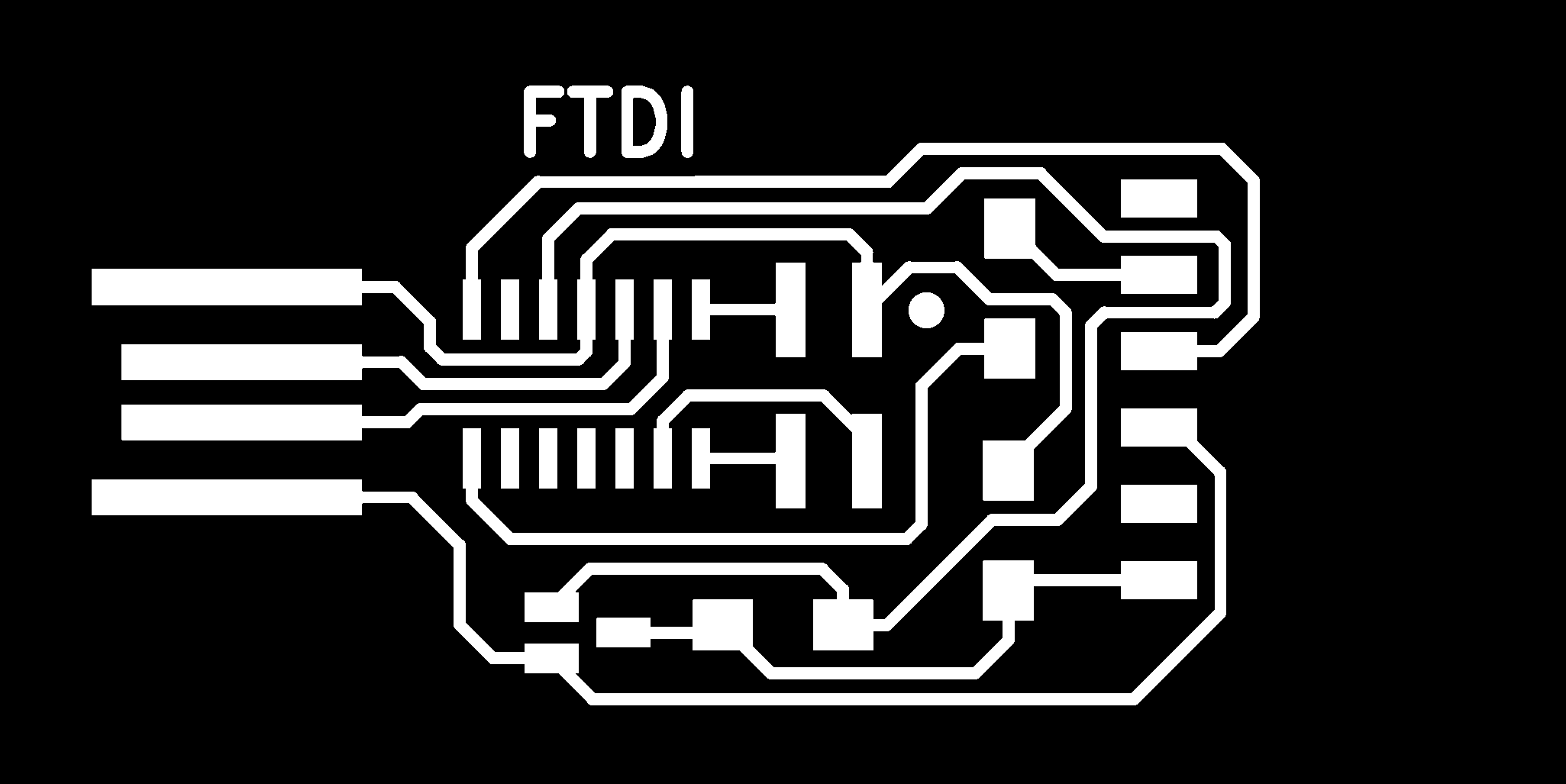
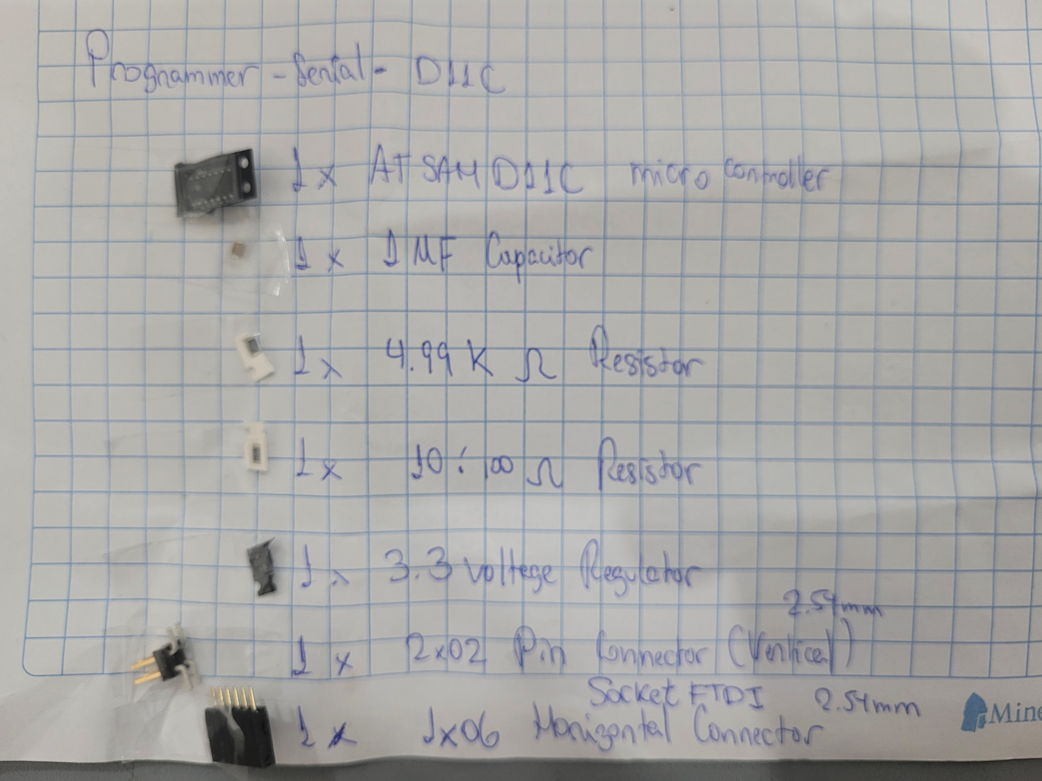
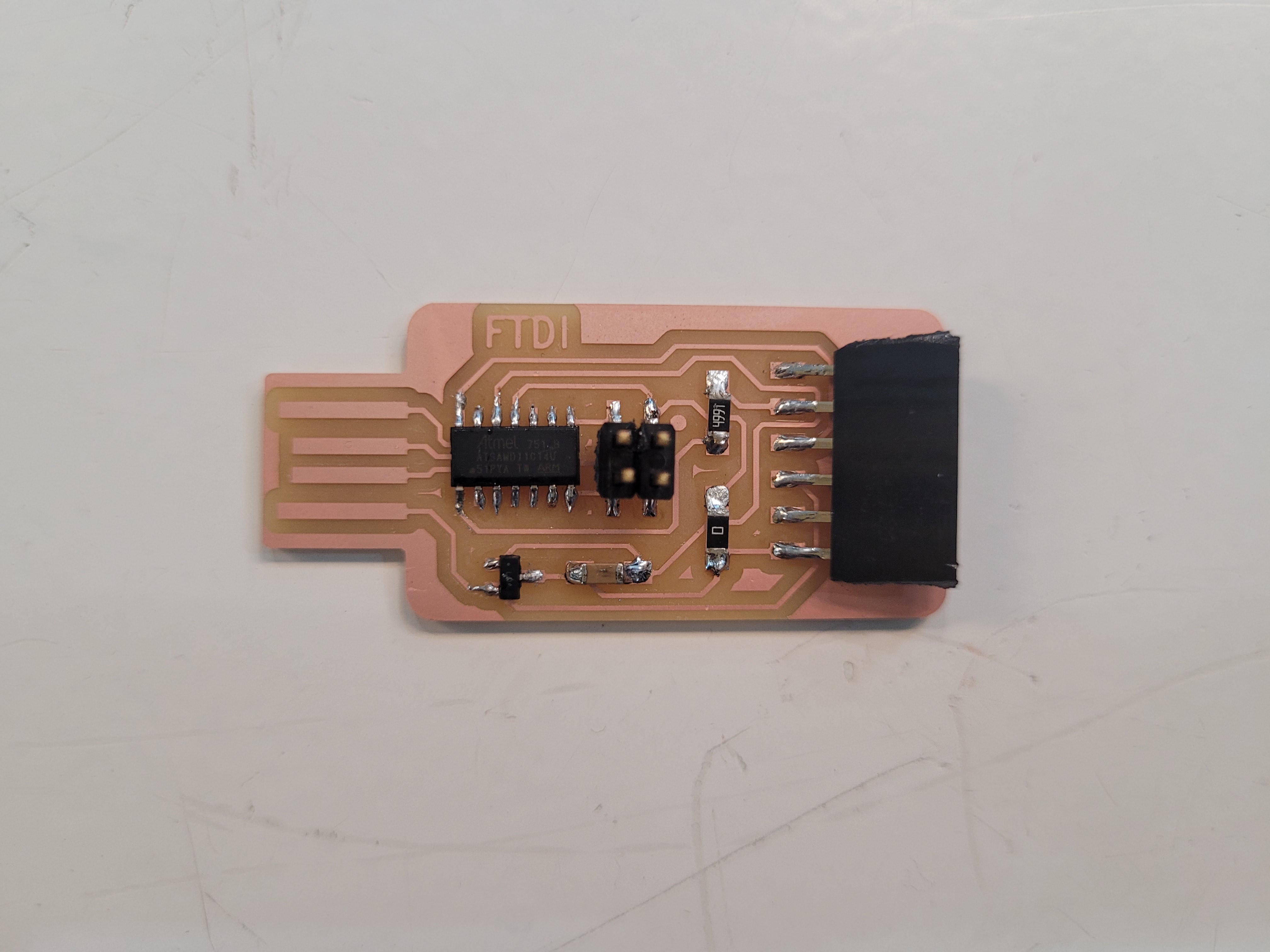
2.- Bridge Serial D11C - The programmer is going to help us to make a serial interface (FTDI) which helps us

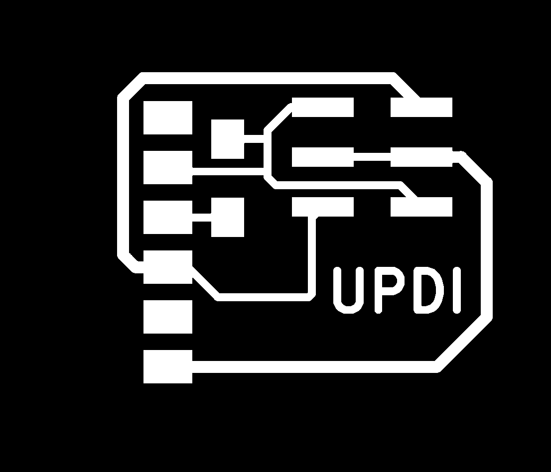
3.- Programmer Adapter Serial to UPDI - It allows us to convert a FDTI bridges to UPDI programmer.

In order to get the files for milling the board in the CNC Machine, we need to use modsproject. It is important to mention that we need to generate two files for milling: the traces and the outline. Also, for each of them we are going to use a different mill that it will be set up on modsproject.
Mods Project
After downloaded the .pngs files of each board from the repository, we need upload these files to modsproject.
Setting PCB Traces
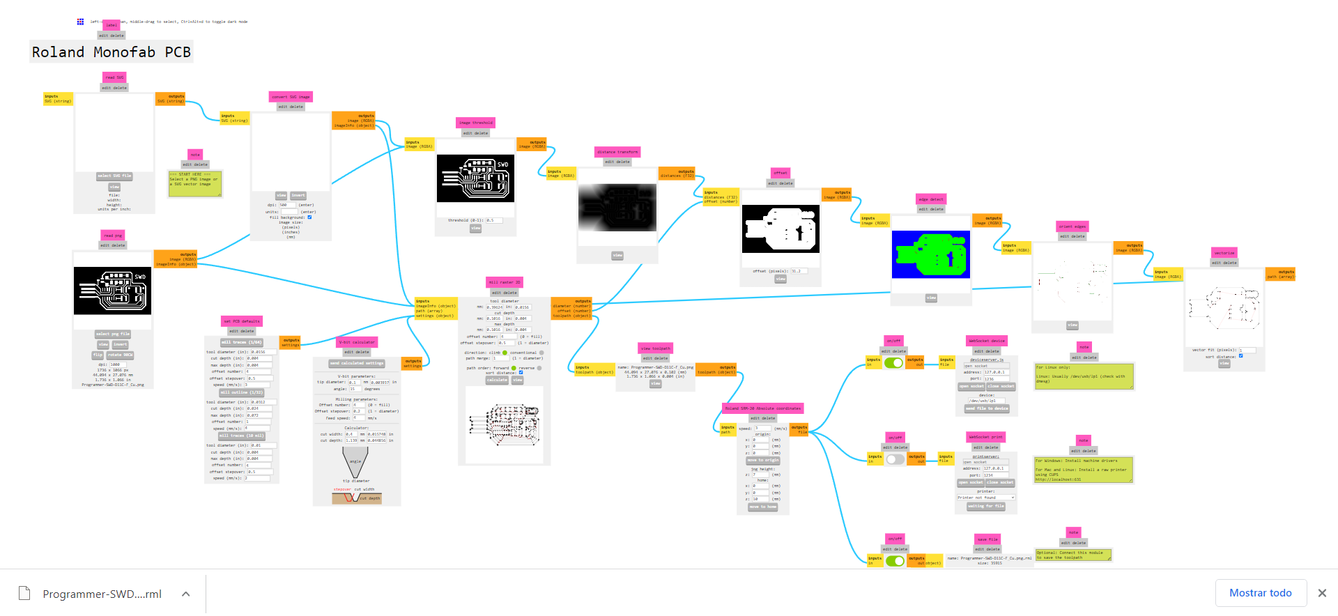
We must follow the next steps: 1.- Right-click on the screen and you can see 4 options, you must select: programs->open program->PCB Absolute. 2.- Upload the image on the read png section because our file has this format: - Change the resolution to 1000 DPI - Check the sizes of the board 3.- Go to “set PCB defaults” section on the “mill traces (1/64)”: - Set the speed to 3m/s - Click “mill traces (1/64)” button 4.- Go to “Roland SRM-20 Absolute coordinates” section: - Change the speed to 3m/s - Set the origin to X0, Y0, Z0 - Set the jog height to 7mm - Set home to X0, Y0, Z10 5.- Join the the output of “Roland SRM-20 Absolute Coordinates” to the input of “Save File” panel 6.- Go to “mill raster 2D” section and click “calculate”
It will be generated automatically a file and one CNC path on the browser. Now, you can go to the machine and upload the file to mill, but something is missing: the outline.
Setting PCB outline
Basically, we have to follow the same steps however we must change the following parameters:
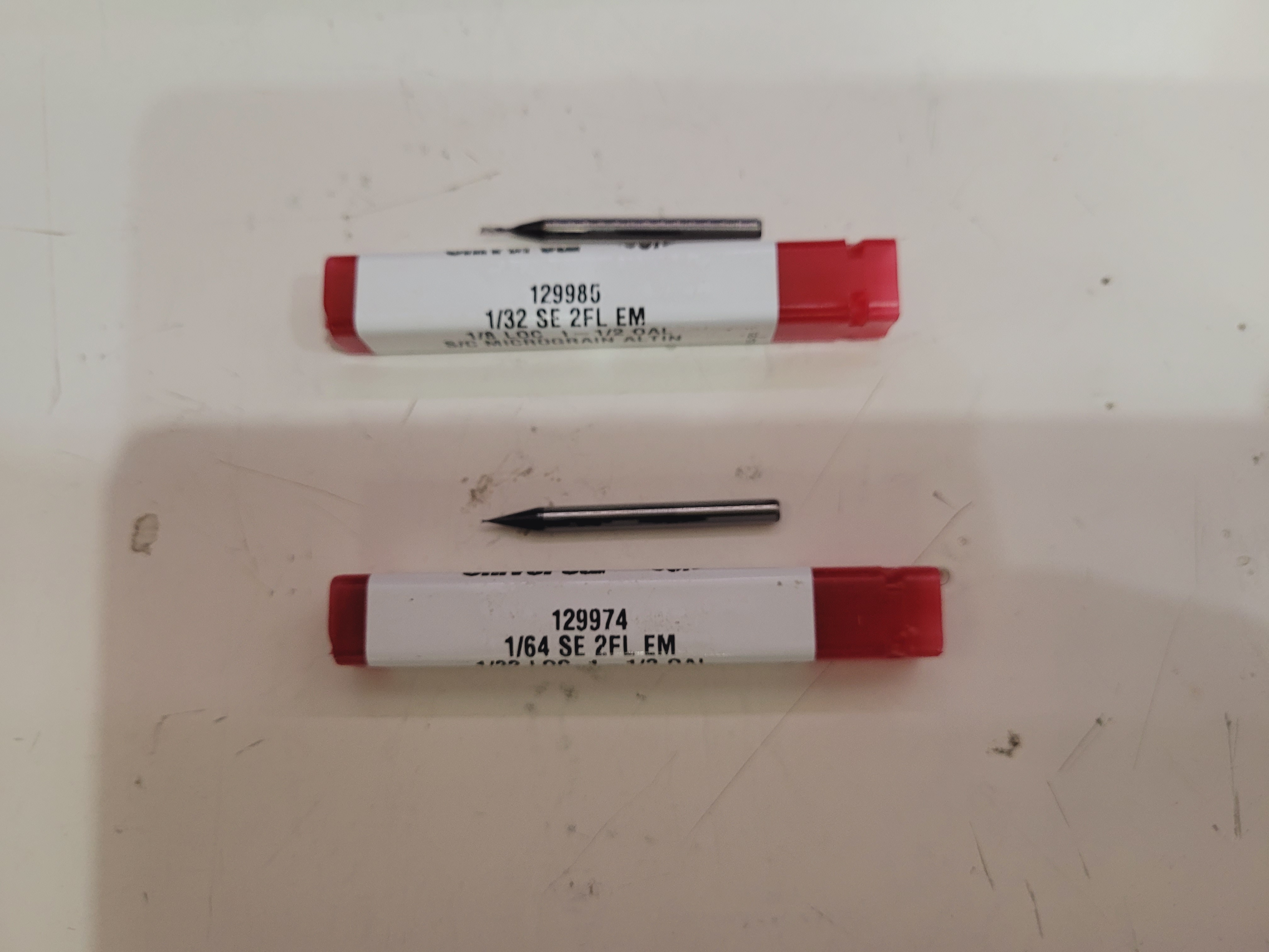
1.- Go to “set PCB defaults” section on the “mill outline (1/32)” - Set the speed to 1.5m/s - Click “mill outline (1/32)” 2.- Go to “mill raster 2D” section: - Check if the “offset number” is setting to 1 instead of 4 - Set max depth to 1.75mm 3.- Go to “Roland SRM-20 Absolute coordinates” section: - Set the speed to 1.5m/s
Programmer SWD D11C Images (Modsproject)
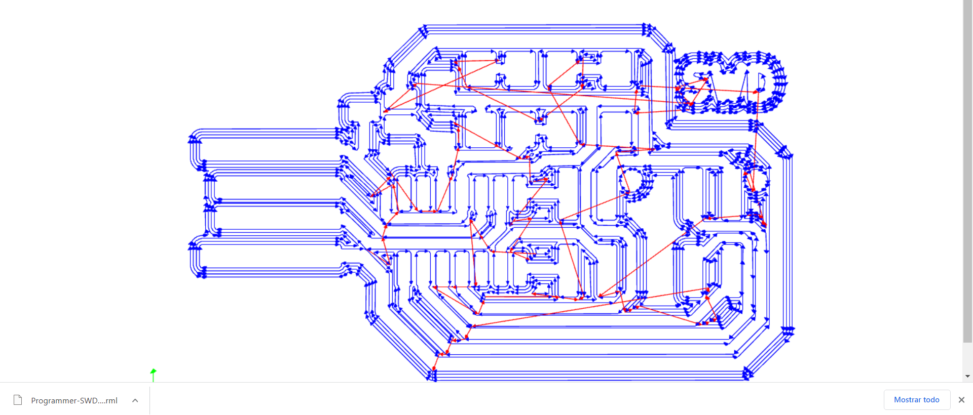 So, we can go to the CNC machine with those files and milling!
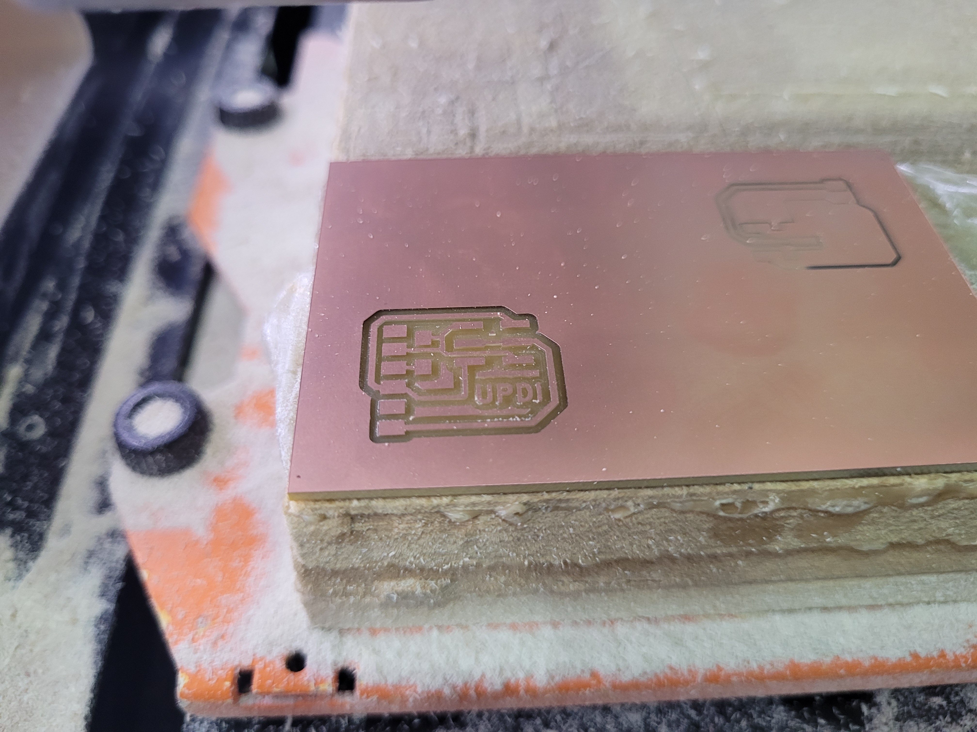
CNC Milling
We are going to use the SRM-20 milling machine that is useful for cutting a variaty of materials. This CNC has a control software or VPanel controller to regulate the machine work-table for changing the mills and for setting the X, Y, Z axes. Besides, it has an independent system that allows us to set of the Z-axis point.

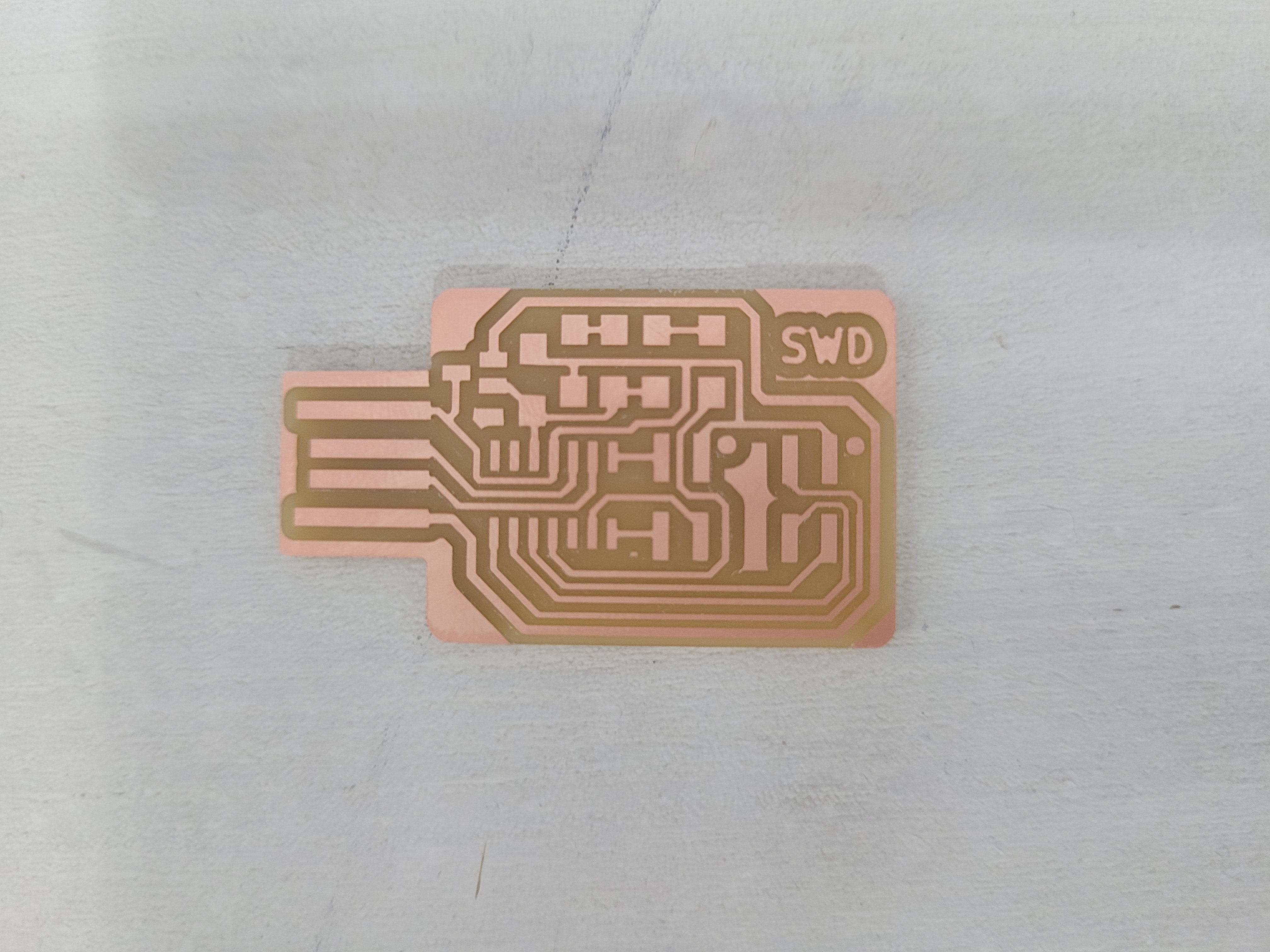
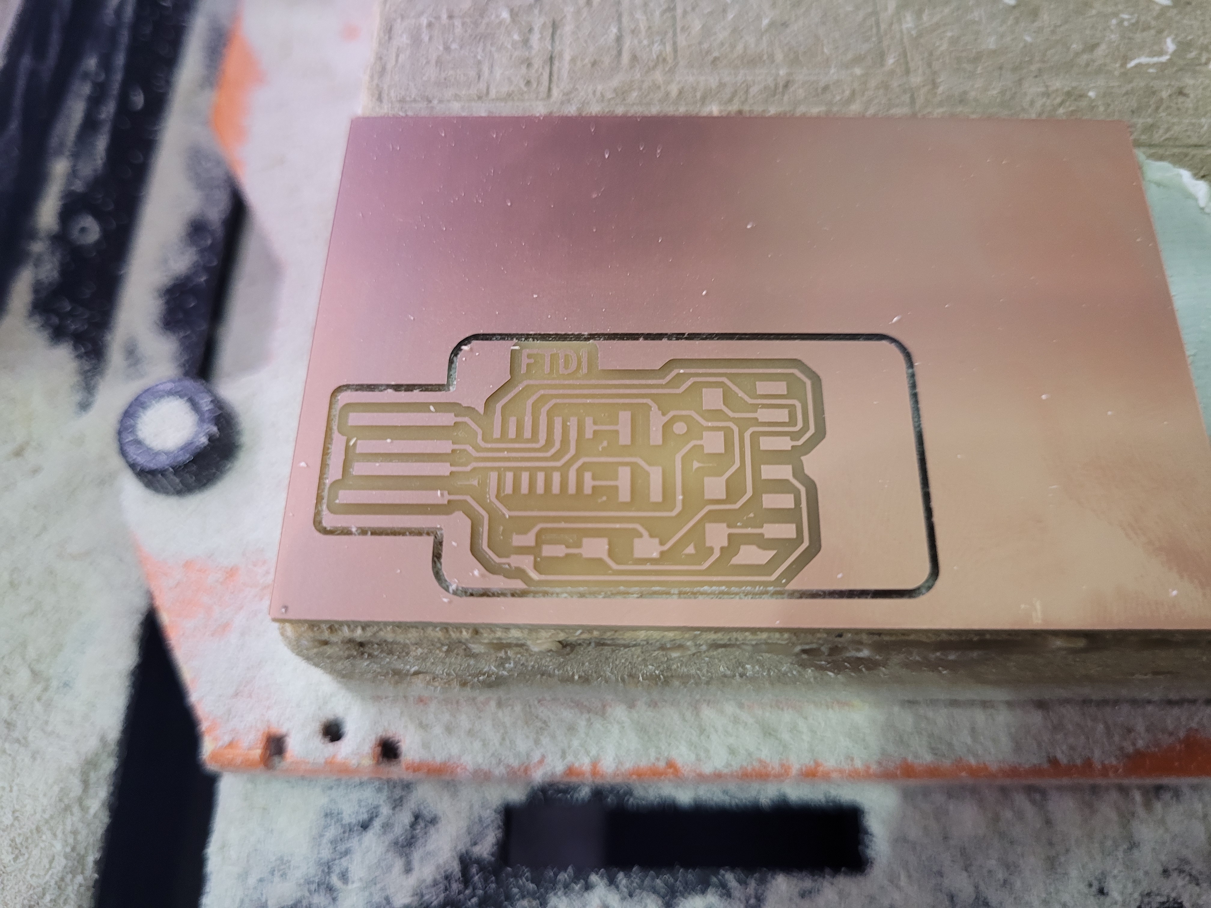
Now for milling the board, we take the cooper plate and put it 2 face tape. We must ensure that the plate has been stuck properly because it might move and cause a bad result. Then, we have to put the correct drill (1/64”) in the machine. Afterwards, we need to set the origin. Using the control software, we set the XY coordinates, do not forget the mill start to the lower left corner of the png image because we set this point on the modsproject. To set the z axis, very carefully we let go of the mill until touch the copper plate, then seth the z=0 and raise it a little bit. we close the security glass and click cut for loading your files. Finally, we click output and the machine are going to start.
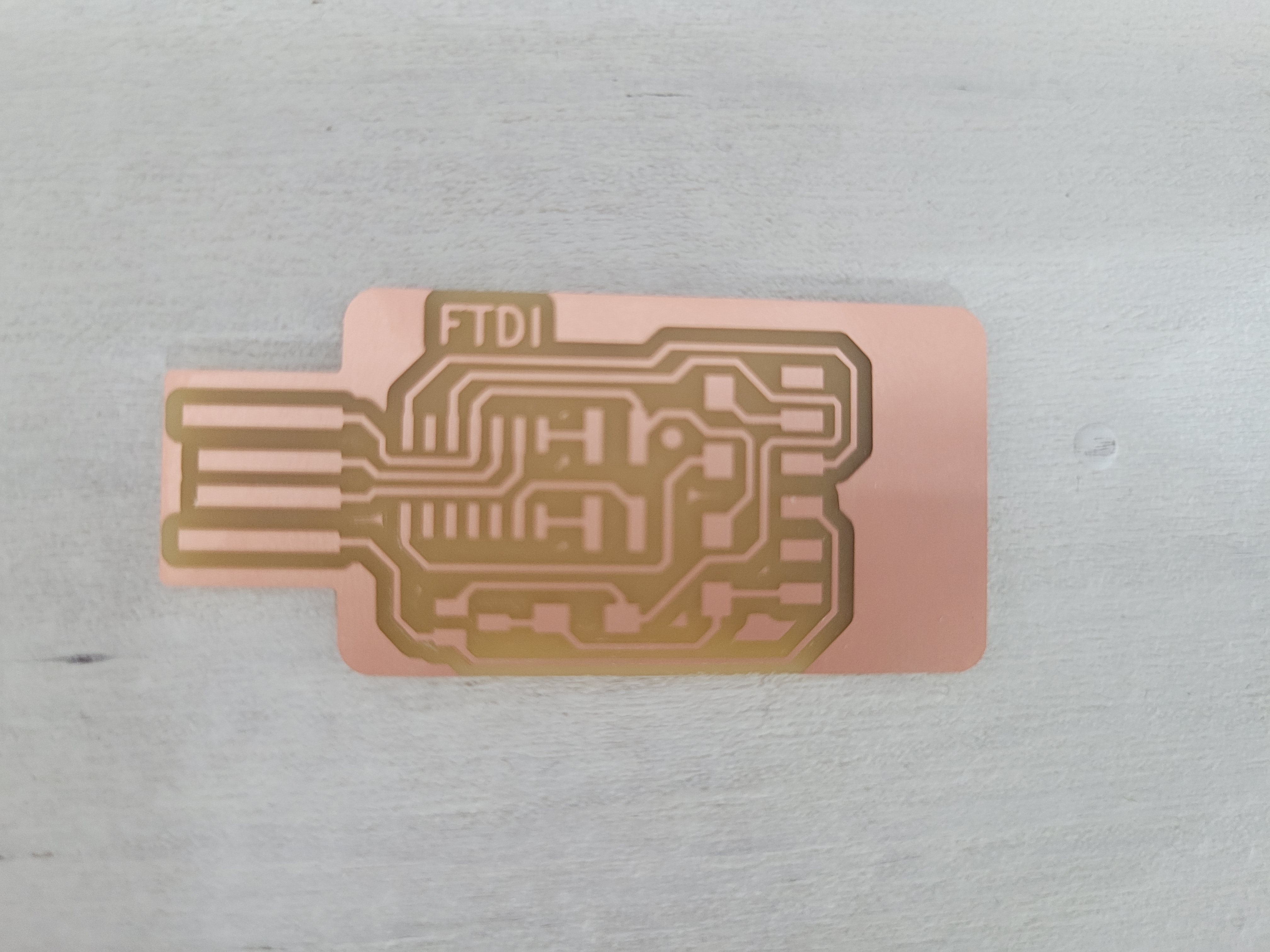
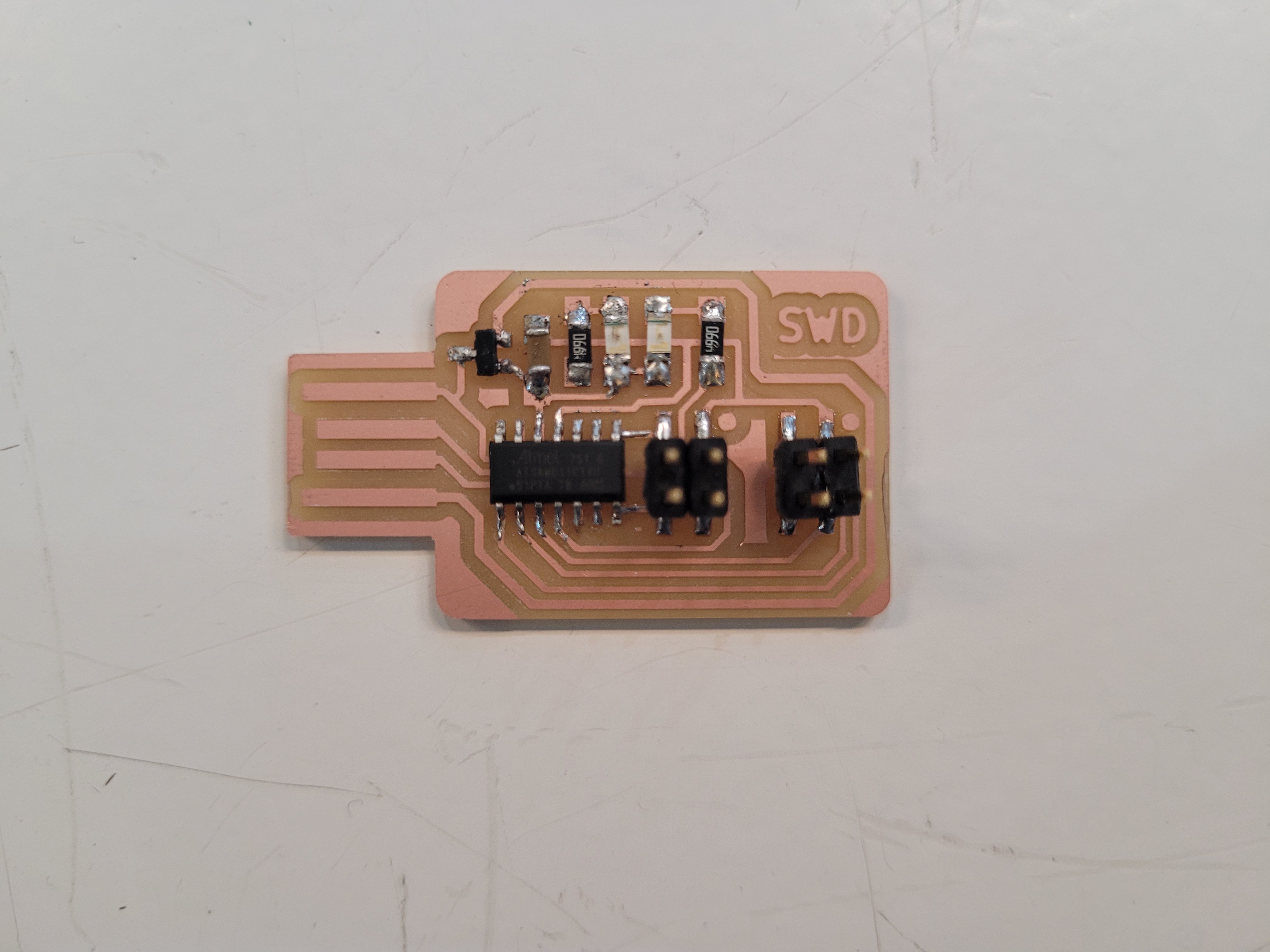
Programmer SWD D11C

Bridge Serial D11C
Programmer Adapter Serial to UPDI
Assembling Electronics Components
I had never soldered electronic components on a circuit board. So, I felt very glad to do it. At the beginning with my first components it seems very easy however when I started to solder on my board I had some problems that is why I recommend see this soldering tutorial.
First, it is a good practice to make a list of all the components that you need. Similar to this picture:
I think that stuffing the components and getting a good result is just practice and I am pretty sure that I am going to improve my soldering skills. However, due to the polarity of the led we have to be careful where we placed it. The polarity need to be tested using the multimeter. When the positive probe (usually red) is touching the anode and the negative probe (usually black) is touching the cathode the multimeter will light up or show a reading. On the other hand, non-polarised components have no polarity and therefore can be connected in any orientation in a circuit and the final result:
Programming the board
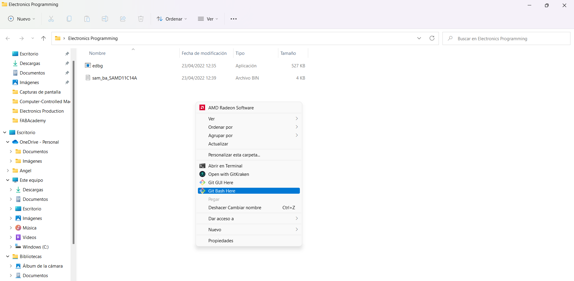
To be honest I thought that this will be the hardest part of all the assignment but this is only an introduction and the main objective is to understand how it works the world of the microcontrollers. First, this files must be downloaded:
Second, right-click under the window and you must go to git bash here and the git window appears.
Third, You must introduce the following commands and you can see the following information:
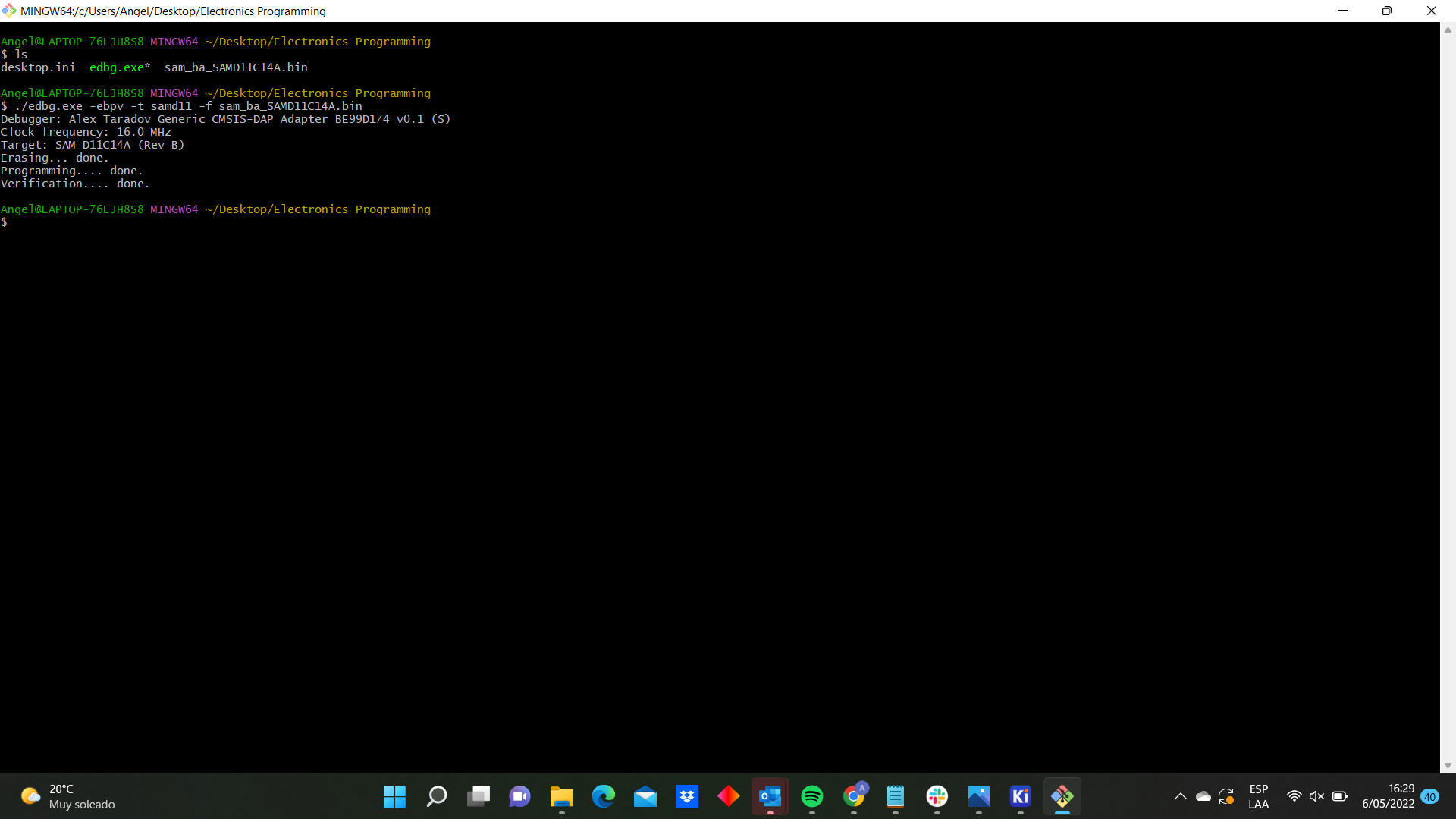

And it is done, you have just programmered your first board.

Group Assignment
Here is the link.
Files
- Adapter.Outline
- Adapter.Traces
- ProgrammerSerial.Outline
- ProgrammerSerial.Traces
- ProgrammerSWD.Outline
- ProgrammerSWD.Traces