14. Networking and communications
Individual Assignment
For this week, We need to create 2 boards and make them communicate between them.
I2C Communication
I2C protocol is used to establish communication between two or more ICs (Integrated Circuits). This protocol In this kind of protocol we have the master device and the slave device. The master device sends and recieves data from the slaves, each slave has an specific address that will be triggered by the master to establish communication with each one of them. When the master wants to communicate with one slave, it sends the address byte to the slave and it knows to wich one is talking to, therefore the slaves sends the message followed by a finish comunication byte. This information is important for designing the boards:
- I2C Communication uses 4 wires, the VCC, the GND to power all the devices and to ports, the SDA and the SCL. SDA is the one in charge to transmit the data, while the SCL is the clock of the signal.
- The SDA (serial data) and SCL (Serial clock) cables each of them need pull-up resistors for both communication lines.
Master board
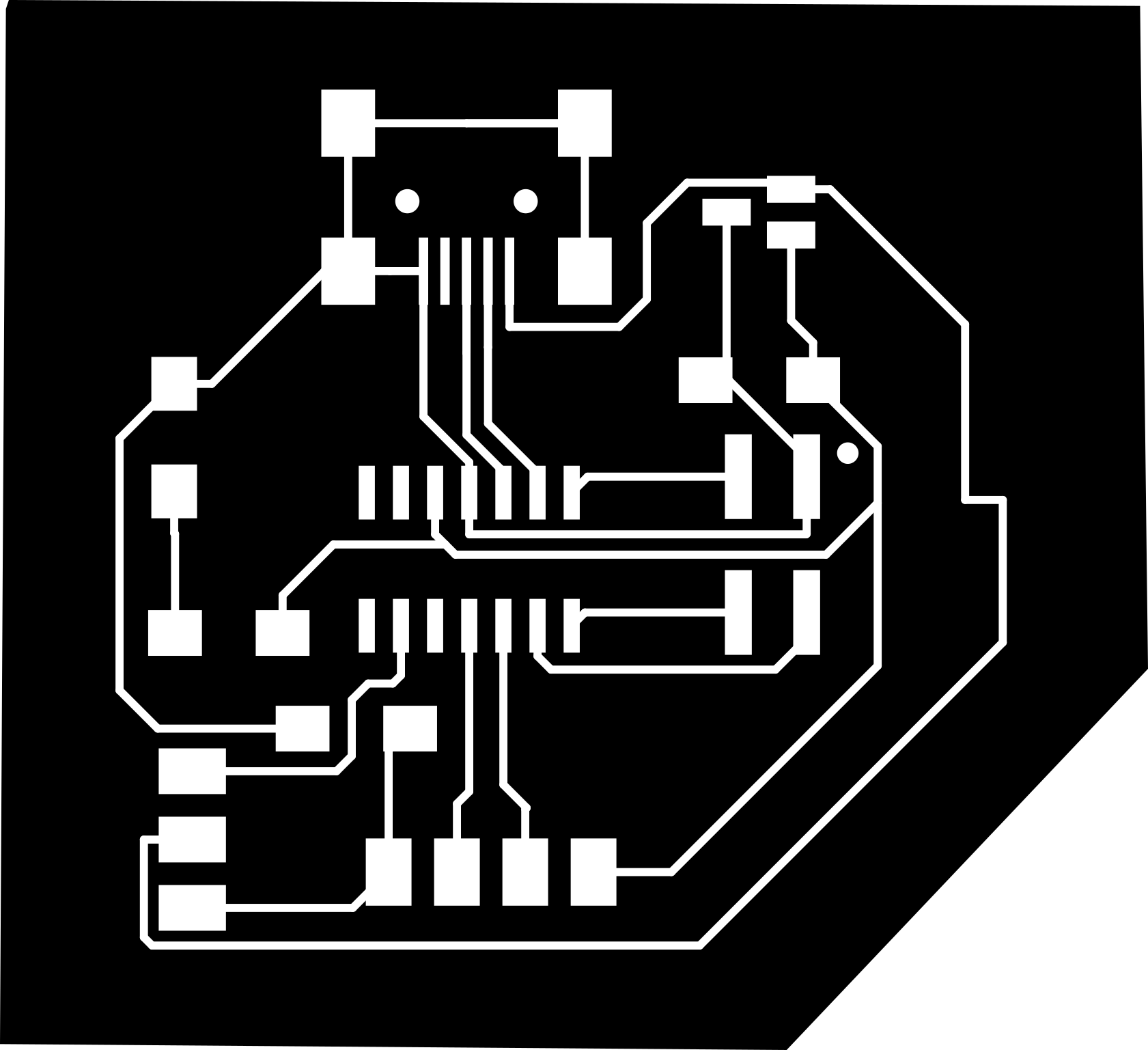
Taking in consideration the previous information I designed the schematic:
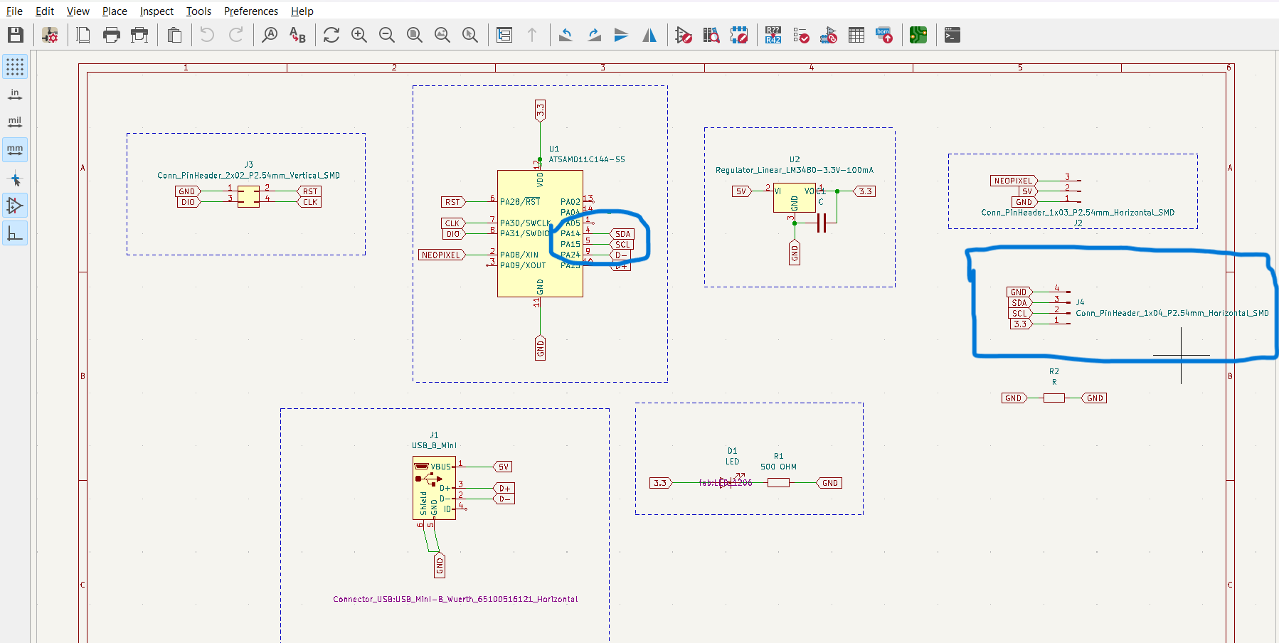
When I checked the SAMD11C datasheet the pins for SDA and SCL are pins PA14 and PA15.
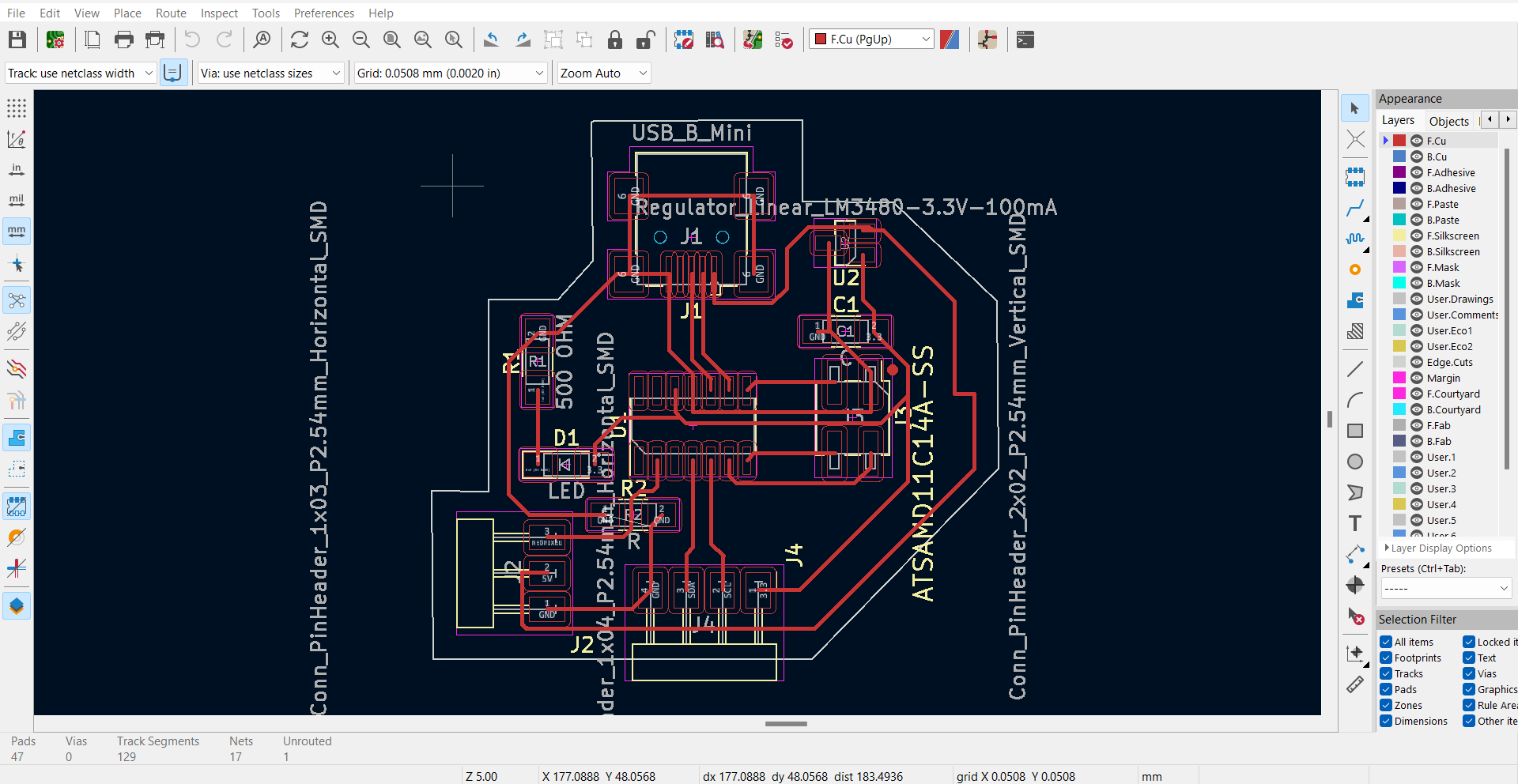
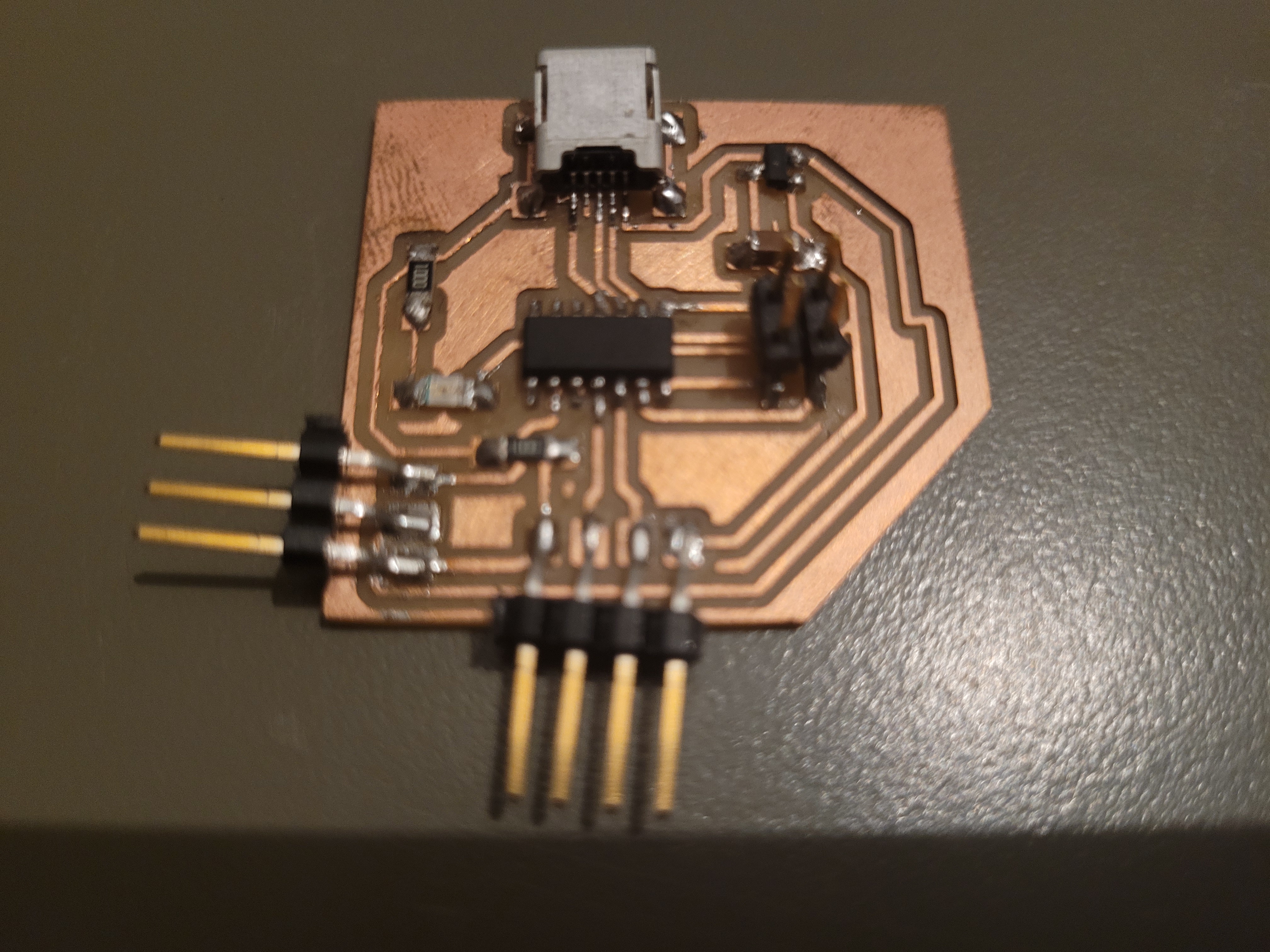
Final result:
Slave board
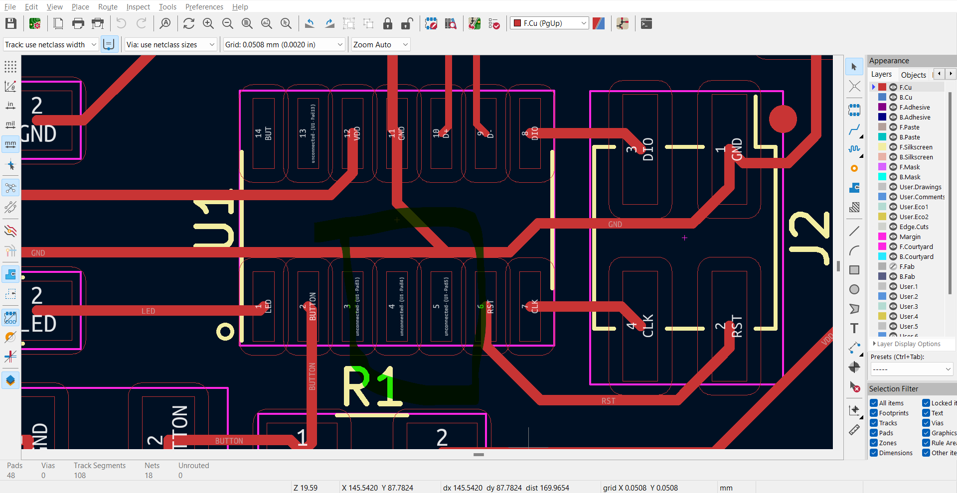
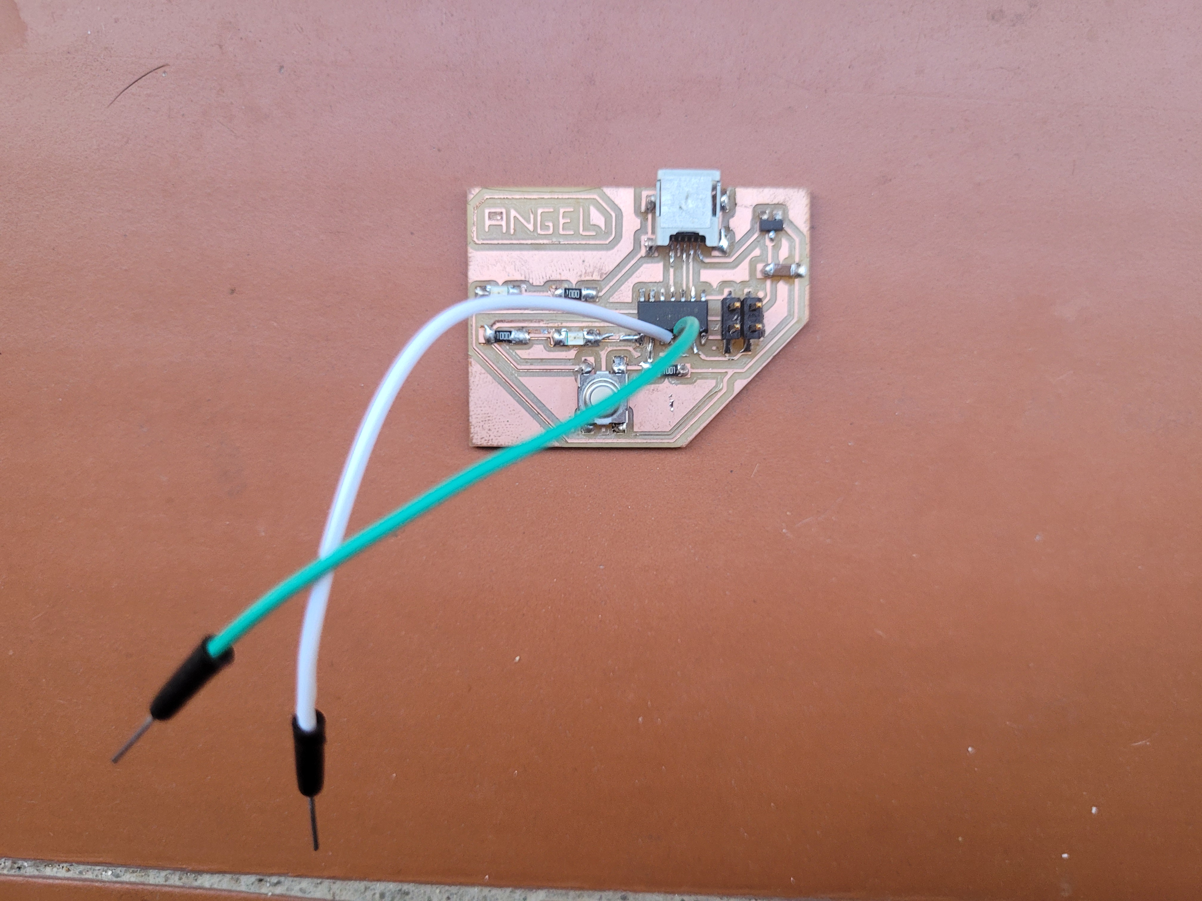
I Knew that I could print the same board but I decided to use a board that have been made in the electronic design week to validate if I add the wires directly to the board will work without any problem. Therefore, Once I found the pins PA14 and PA15 I soldered two wires. Here is the schematic where you can see the pins PA14 and PA15.

In the following screenshot, it can be seen where are the pins PA14 and PA15.
Final result:
Programming
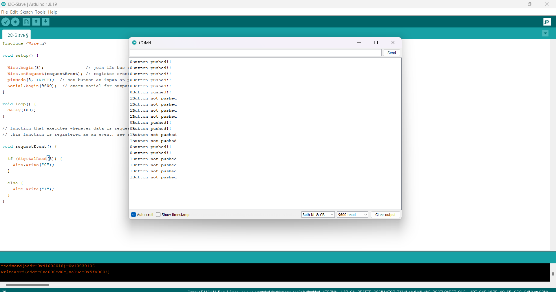
Slave Code
In the slave code we must define the address (in this case, the address is 8). Besides, the requestEvent executes whenever data is requested by the master. Finally, the void requestEvent() shows the state of the button.
#include <Wire.h>

void setup() {

  Wire.begin(8);                // join i2c bus with address #8
  Wire.onRequest(requestEvent); // register event
  pinMode(8, INPUT);  // set button as input at pin 5
  Serial.begin(9600);  // start serial for output
}

void loop() {
  delay(100);
}

// function that executes whenever data is requested by master
// this function is registered as an event, see setup()

void requestEvent() {

  if (digitalRead(8)) {
    Wire.write("0");
  }

  else {
    Wire.write("1");
  }
}
Master Code
As can be seen, I did not declare a number and the requesEvent. Besides, in this part we must decide the message when the button is pushed or not.
#include <Wire.h>

void setup() {
  Wire.begin();        // join i2c bus (address optional for master)
  Serial.begin(9600);  // start serial for output
}

void loop() {

  Wire.requestFrom(8, 1);    // request 1 byte from peripheral device #8
  while (Wire.available()) { // peripheral may send less than requested
    char c = Wire.read(); // receive a byte as character
    Serial.print(c);         // print the character

    if (c == '1'){
      Serial.println("Button not pushed");
    }

    else{
      Serial.println("Button pushed!!");
    }
  }

  delay(500);
}
Final Result
Connectig both boards GND to GND, SCL to SCL, SDA to SDA and 3.3V to 3,3V we will be able to send information from the master board to the slave board. the slave board could send data back if the master ask fo it. In my case, I used a breadboard because as I mentined I need to add a resistor for the SCL and SDA.
In this picture you can see the resistor.
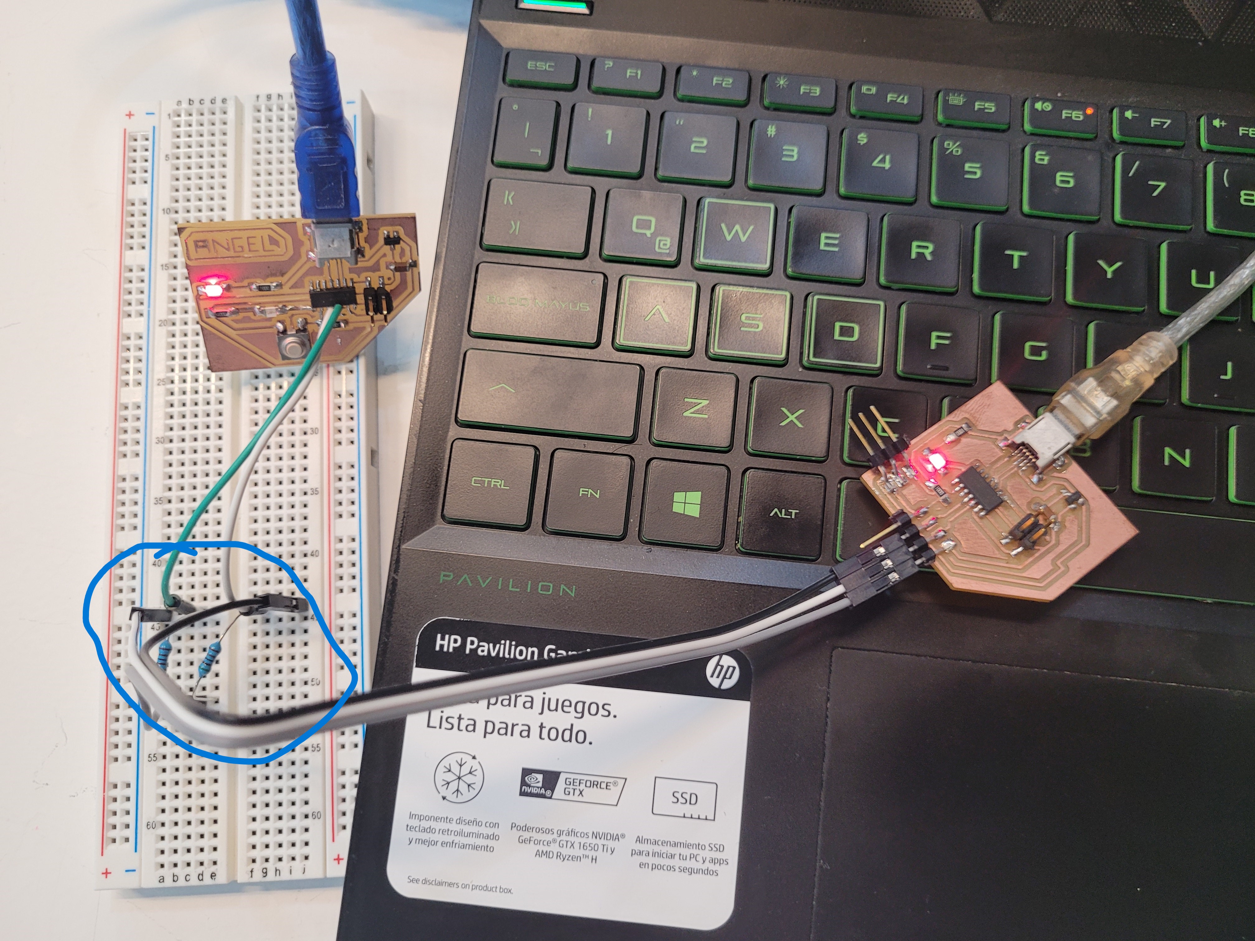
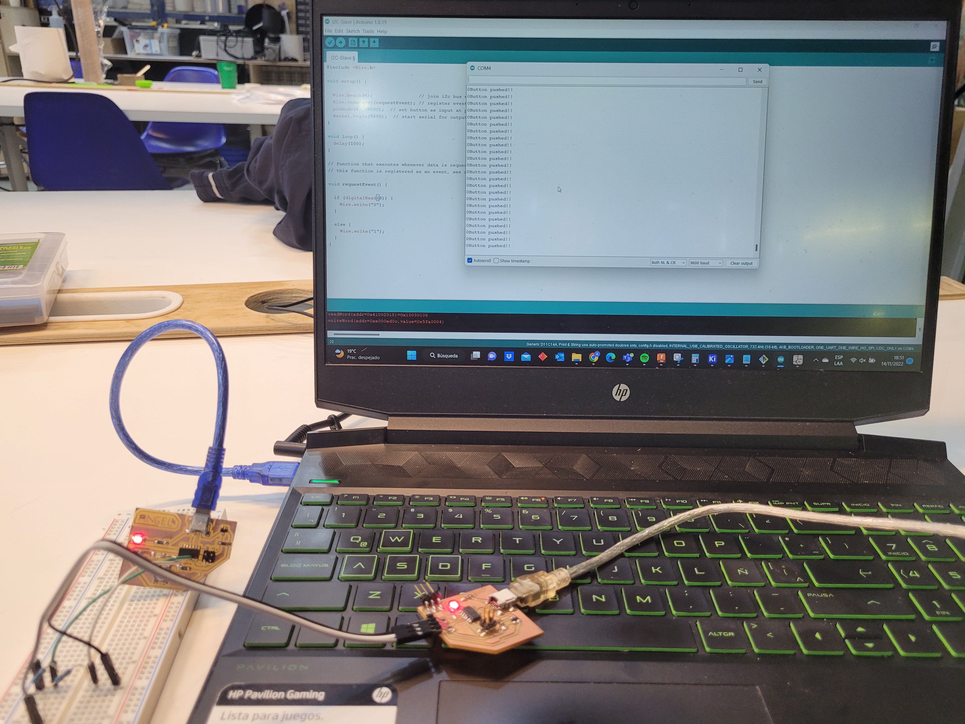
This is the final result:
Networking&Communications from Angel Erazo on Vimeo.
Group Assignment
Here is the link
Files
- I2C-Master.ino
- I2C-Slave.ino
- DesignKicad.sch
- DesignKicad.pcb
- DesignKicad.pro
- Traces.png
- Outline.png
- Traces.path
- Outline.path