9. Embedded programming
Individual Assignment
For this week, we have to read the data sheet of our microcontroller (SAM D11C) and program our board to do something. The good part is we have already designed and programmed our board on week 6.
Reading The Datasheet for SAM D11C Microcontroller
Before starting to program a board, the first thing that we have to is read the datasheet of the microcontroller, to know how it works and its capabilities. In my case, I am using the SAM D11C 14A microcontroller and you can find the datasheet in this link. I believe that the most important information to extract is about what pins you have in your microcontroller to know where you have to connect the components so they can work properly.
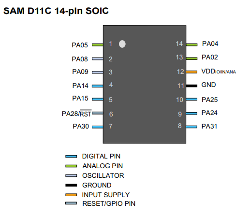
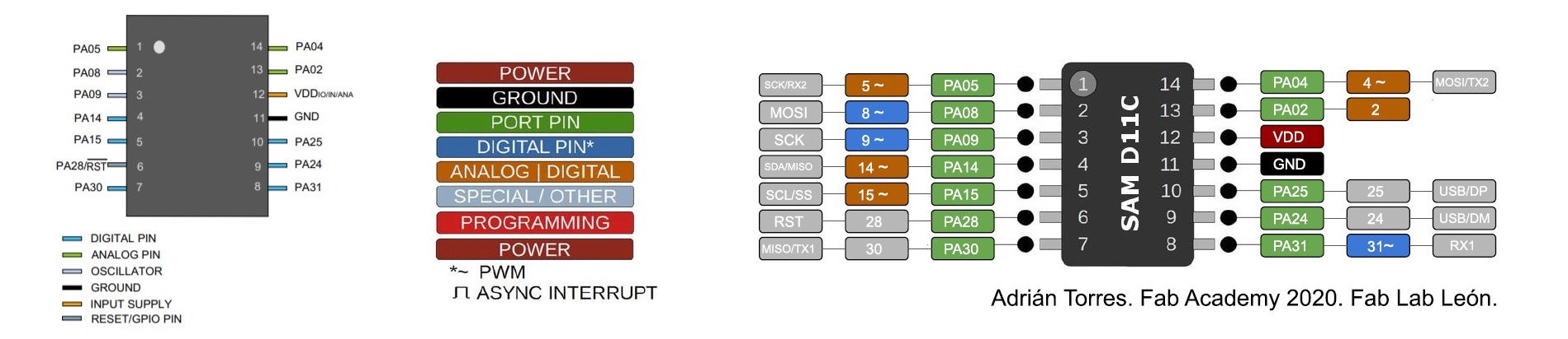
So, the most important pin to take in consideration are:
- VDD: Supply voltage.
- GND: Ground.
- Digital pins: PA02, PA04, PA05, PA08, PA09, PA14, PA15, PA31.
- Analog pins: PA02, PA04, PA05, PA14, PA15.
- USB pins: PA24, PA25.
Another important thing that the data sheet tells us is what pin is for analog or digital input component; for example, if you are using a pressure sensor (analog component) you have to connect it to an ACD (analog to digital converter) port otherwise the microcontroller isn’t able to transform the information that is receiving from the sensor to a digital data.
Flashing the bootloader
This part I did in the week 4. First, this files must be downloaded:
- EDBG
- Free dap Binary (sam_ba_SAMDC11C14A) that you can find it here on the Flashing Firmware part.
Second, right-click under the window and you must go to git bash here and the git window appears.
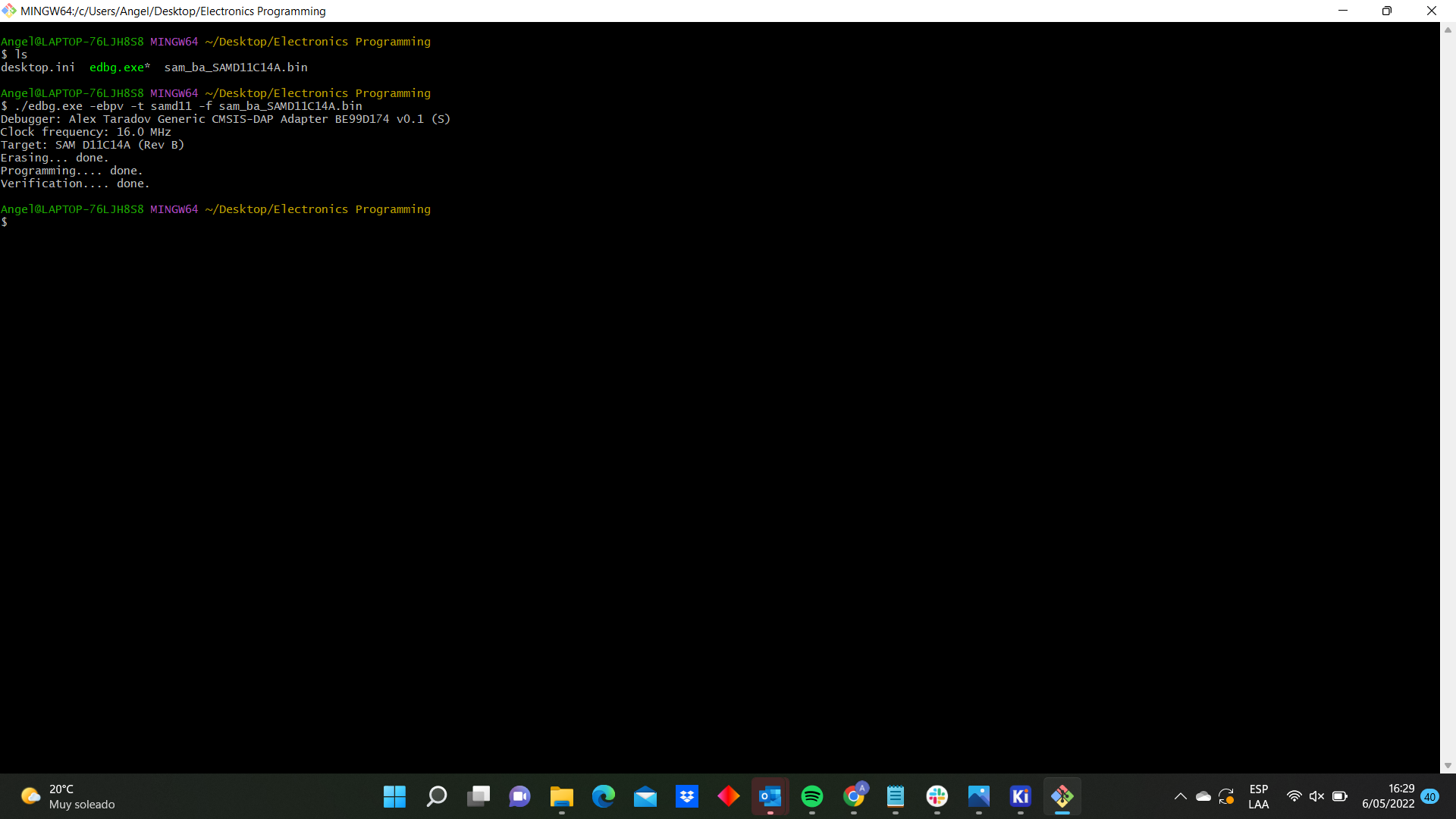 Third, You must introduce the following commands and you can see the following information:

Programming Using Arduino
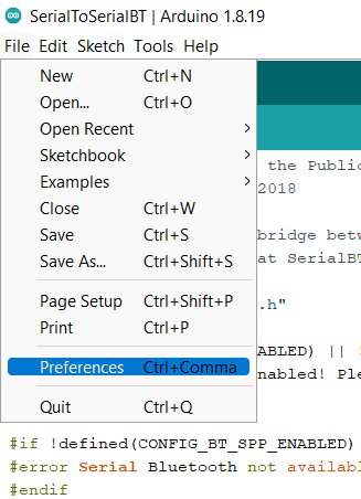
This part I explained in the week 6. To program in Arduino, we need to do the following steps:
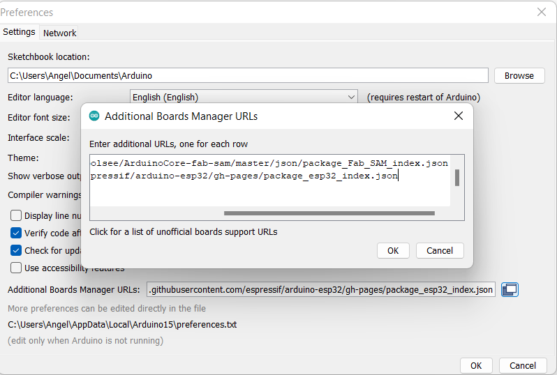
1.- File -> Preferences -> Additional Boards Manager URLs I copied this URL: https://raw.githubusercontent.com/qbolsee/ArduinoCore-fab-sam/master/json/package_Fab_SAM_index.json.
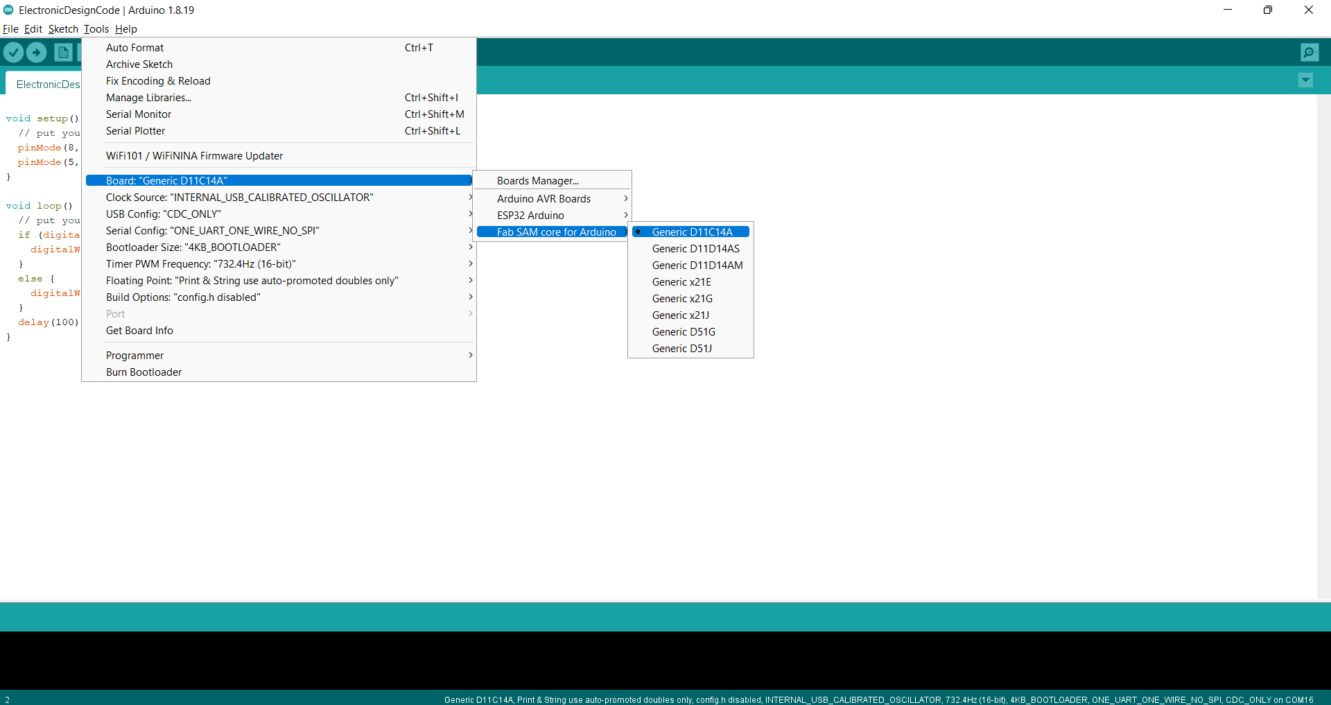
2.- Tools > board > board manager. In the browser I typed “fab”, I can see the Fab SAM core for Arduino by Fab Foundation and I installed.
3.- Finally, I configure the settings.
Afterwards, I recommend you to check this link where you can find: the functions, values and structure. Something very important is the structure that allows to understand how the program works. I am going to explain this with my next code:
int pushButton=0; //button´s state
int state=0; //0=led off, 1=led on
int pushButtonPrev=0; // previous button's state
The first part is for defining a series of global variables. Here, I defined the button’s state, the led’s state and the previous button’s state as integers (int). By the way, I would have added as integers the Led and the button but There is no problem because I defined them few lines later.
void setup() {
  pinMode(8, INPUT);
  pinMode(5, OUTPUT);
}
the second part is the void setup(). This function is the first one called by the program and it runs one time when the board is powered. Here are defined the settings of the board, the things that will not change during the running time to set them first and then pass to the loop.
void loop() {
  pushButton = digitalRead(8);
  if ((pushButton == HIGH)&&(pushButtonPrev==LOW)){
    state=1-state;
   }
  pushButtonPrev=pushButton;
  if (state==1){
    digitalWrite(5, HIGH);
  }
  else{
    digitalWrite(5, LOW);
  }
  delay(100);
}
In the last part there is the void loop() function. Here I defined the principal code which are going to execute in a loop, repeatedly, until the board gets disconnected. Here you can see a video of my final result:
Programming1 from Angel Erazo on Vimeo.
Besides, I wanted to practice and I did a second code.
int i=0;
void setup() {
  // put your setup code here, to run once:
  pinMode(5, OUTPUT);
}

void loop() {
  // put your main code here, to run repeatedly:
 for(i=0; i <= 255; i++){
    analogWrite(5, i);
    analogWrite(5,255-i);
    delay(25);
  }
  for(i=255; i>=0 ; i--){
    analogWrite(8,i);
    analogWrite(5,255-i);
    delay(25);
  }
}
Here you can see a video with my final result:
Programming2 from Angel Erazo on Vimeo.
C code
To practice another programming language I checked the book Make AVR Programming by Elliot Williams, which explains about C code with Arduino IDE (This was a recommendation of my instructor Josep).
I have to say that the book has all the details to learn how to write in C code. You can downloaded the library at GitHub and you can see that the repository it has been divided in each chapter of the book with its own code and the explanation.
So, I checked the chapter 2 and I decide to code with a simple operation: Blinking Led’s. Here is the code
// ------- Preamble -------- //
#include <avr/io.h>                        /* Defines pins, ports, etc */
#include <util/delay.h>                     /* Functions to waste time */


int main(void) {

  // -------- Inits --------- //
  DDRB |= 0b00000001;            /* Data Direction Register B:
                                   writing a one to the bit
                                   enables output. */

  // ------ Event loop ------ //
  while (1) {

    PORTB = 0b00000001;          /* Turn on first LED bit/pin in PORTB */
    _delay_ms(1000);                                           /* wait */

    PORTB = 0b00000000;          /* Turn off all B pins, including LED */
    _delay_ms(1000);                                           /* wait */

  }                                                  /* End event loop */
  return 0;                            /* This line is never reached */
}
Group Assignment
Here is the link.