3. Computer Aided design
For the assignment of this week I have to create 2D and 3D designs in different softwares. We have been taught at fab lab some softwares such as Rinoh and Grasshopper, Fusion 360. Also, I checked all the adittional information and there are softwares that are going to be very useful. So, let is start!
2D Design - KRITA
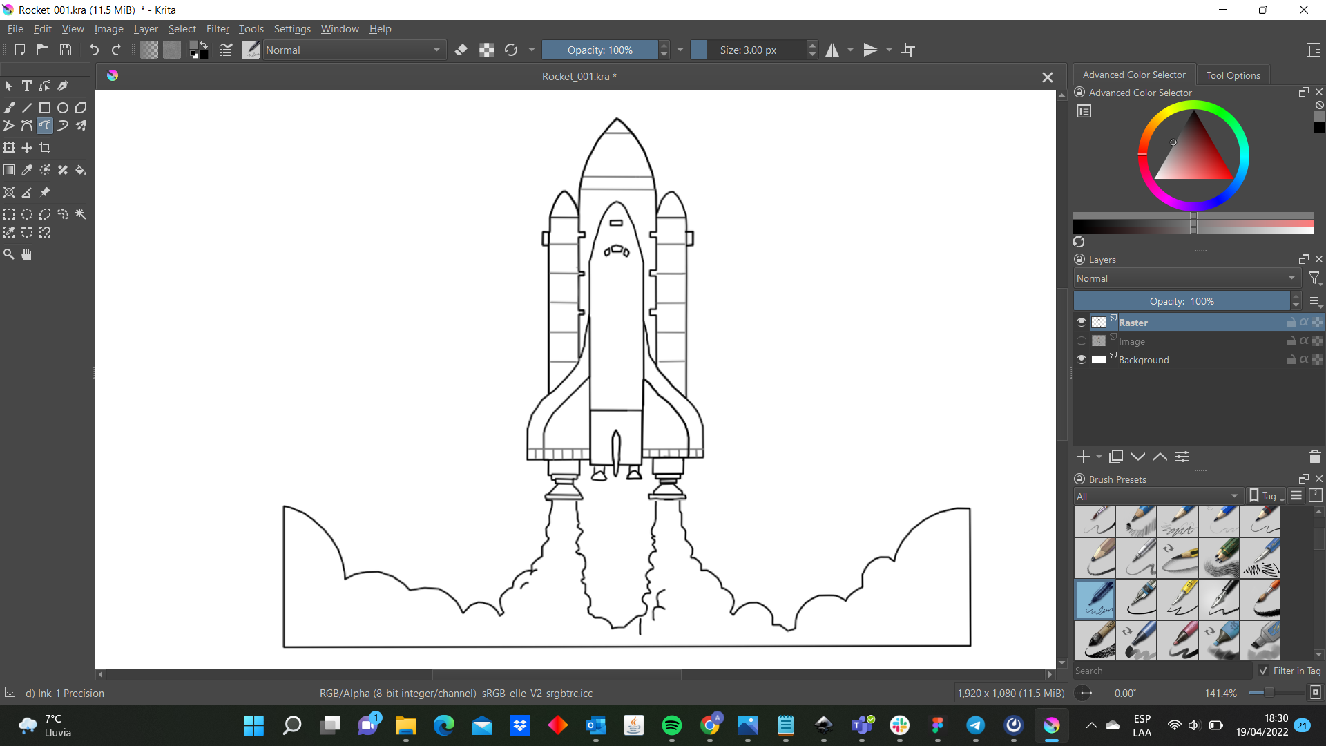
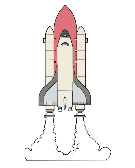
To practice this kind of design I chose Krita because it seems Adobe Illustrator with all the bars and options distributed in the same way. First, I downloaded the program from the website and installing is very easy. Then, I was thinking of what I am going to design?. Fortunately, It did not take me too much time as one image came to my mind quickly and it was a rocket. This my opportunity to design my own rocket. I looked for some picture to guide me and I found this one:

First, when I saw the software I got surprised because the first thing that came to my mind was Adobe Illustrator. It looks pretty similar and I thought that it would a copy but I could find a command that I had not seen and is called “Brush Presets”.
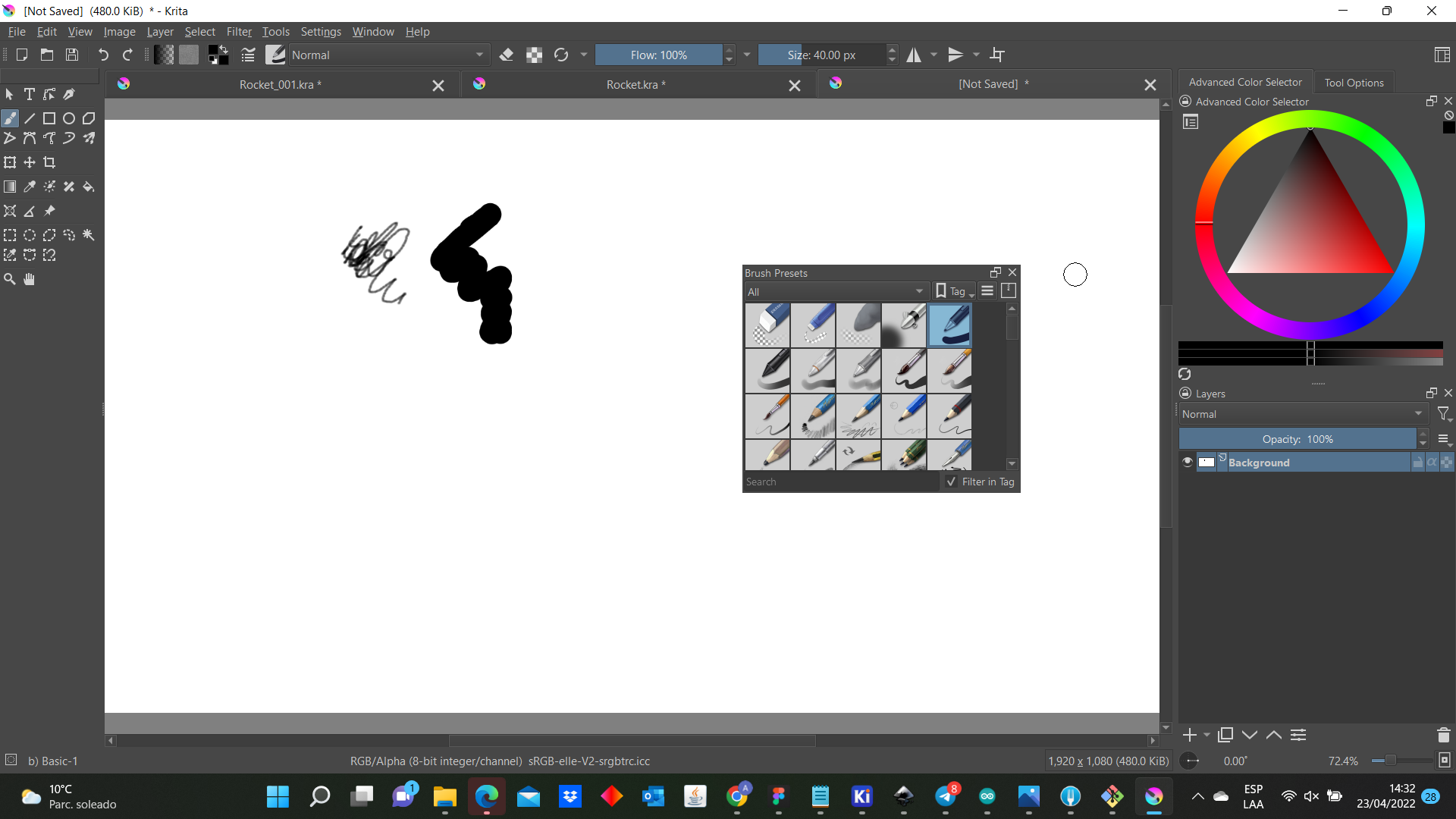
The command is easy to understand and it showed that is useful to create illustrations. Then, I started to create my design I pasted the image and I decided to work with bezier curva tool command which allowed me to draw the image’s outline. Then, I tried to use the others options and it helped me to create the part of the outline with more detail.
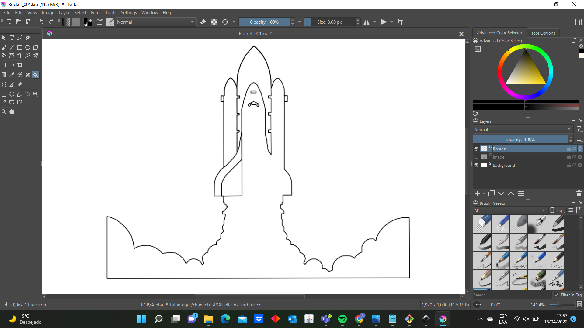
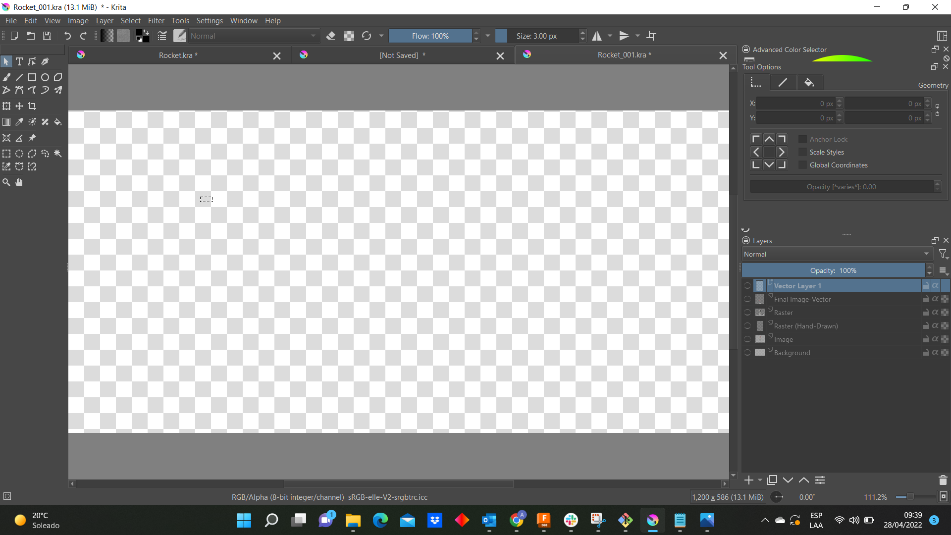
Definitely, it is not to easy start to create this image from zero because I had to use the erase command many times but it is just a matter of practice. Besides, I could practice how to use the layers and their functions. For example in the next you can see that I divided my sketch in 3 layers: Background, Image and Raster. Later, I added 3 more layers (Raster-Hand Drawn, Final Image-Vector and Vector Layer 1)
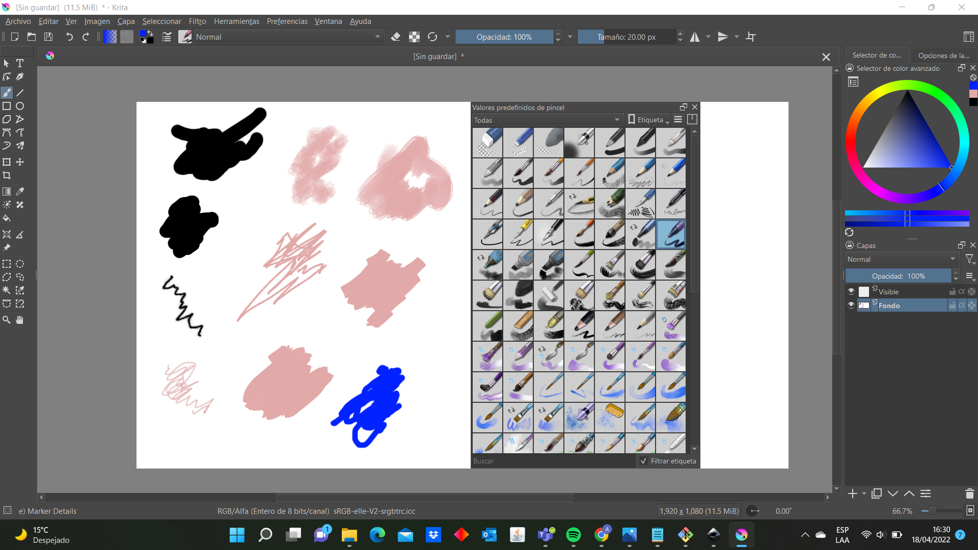
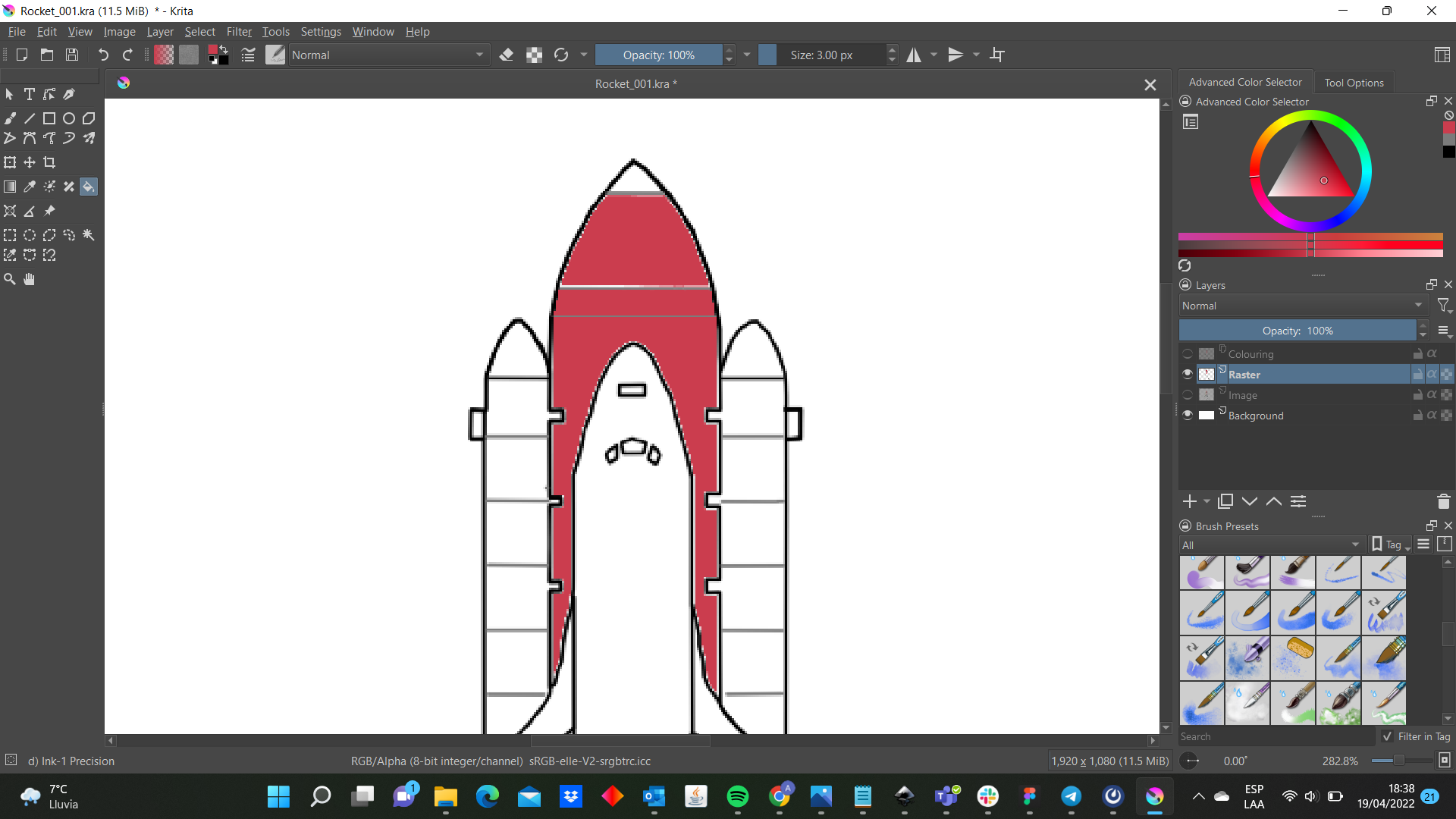
Then, The painting time began and I used the fill tool command (left side) and looked for the colors (the triangle on the right side).
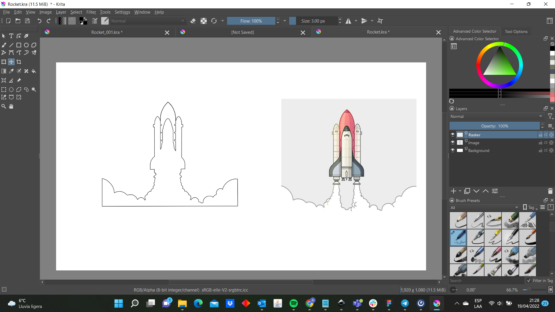
Finally, I practiced a little bit with the vector. By the way, I did not realize that If had started my drawing in a vector layer, I could have been able to use the bezier curva tool as well. However, I can see that the lines in a vector layer are thicker than drawing in a visible layer. Therefore, it depends on what you will be design to choose one command. Here there are son pictures of my vectors:


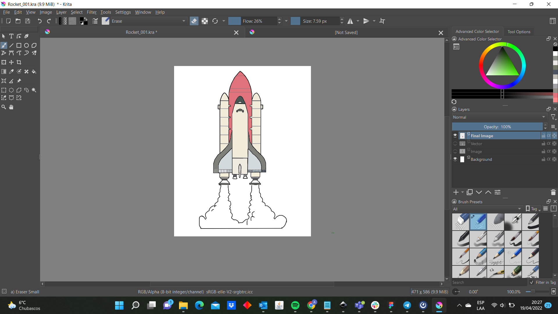
And my final result is:
I think that I will be use as icon for my web page. I have to say that really enjoyed working on Krita and I would like to design some illustrations later.
3D Design - SCULPTRIS
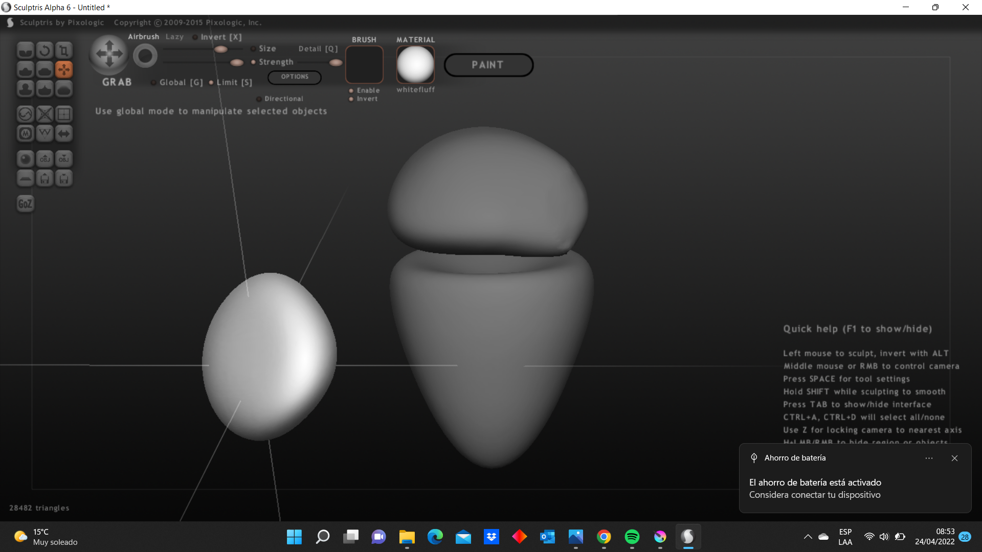
Now it is time for 3D Designs. Sculptris caught my attention because it seems very intuite and really interested that it will be useful for the upcoming weeks. I thought that some animated character of one movie or serie will be better for practicing and learning about this tool. I like pixar movies which have meaningful message on each of them and for me Wall-E is one of the best movie. So, I choosed to design Eve, the wall-e’s partner.

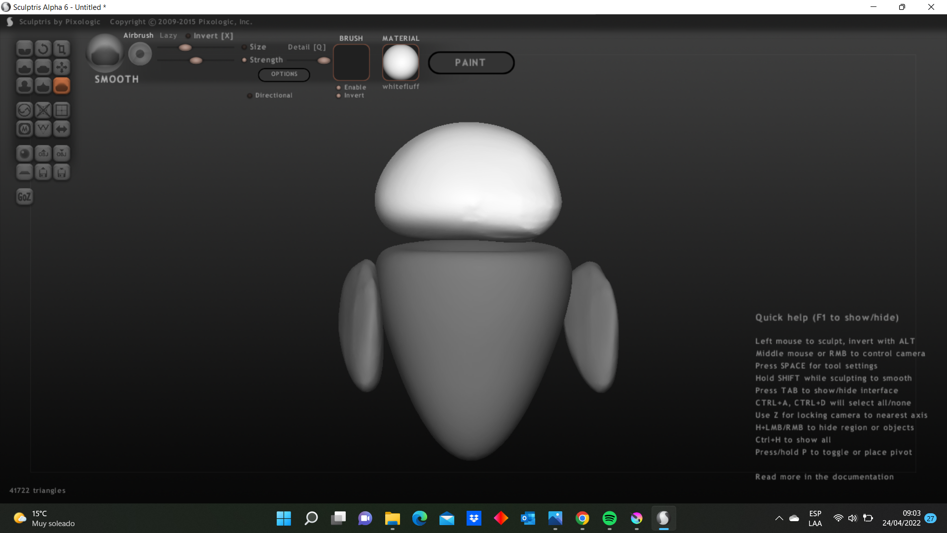
I started to use the grab command to stretch the lowest part of the sphere and change the size. Then, I added 3 spheres for the head and 2 arms. Also, I used the smooth command because when I stretched all the parts did not look nice so it allowed me to get a better finish of the body.

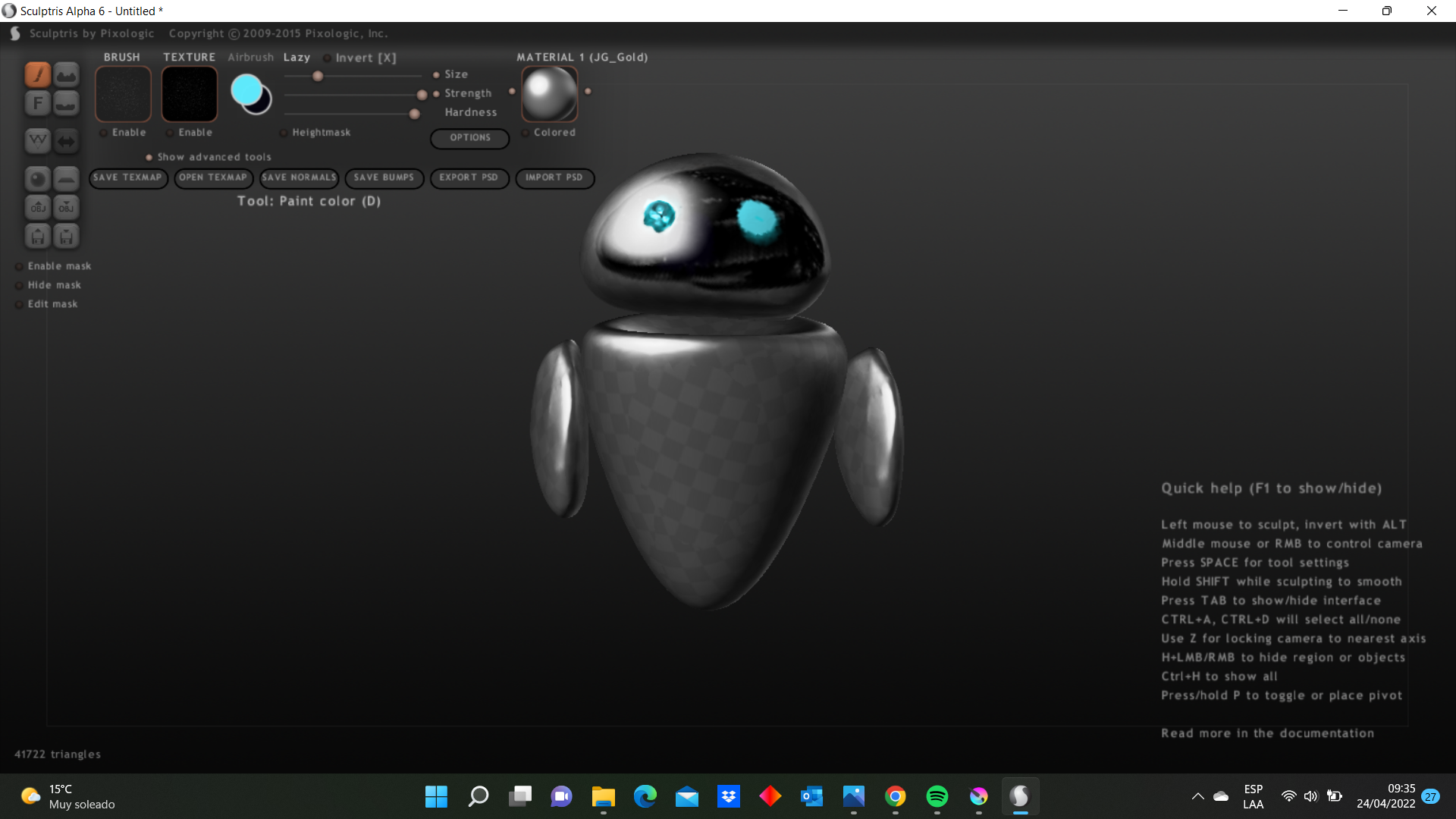
However, here comes one problem. However, here comes one problem. To design the face we must go to paint command but I did not realize that If I enter to this option I will not be able to come back and make changes in the model. That is why the design’s back does not look nice. So, I changed it. And my final result is this:
I like to work with this tool, I will try to use it later.
3D Design - FUSION 360
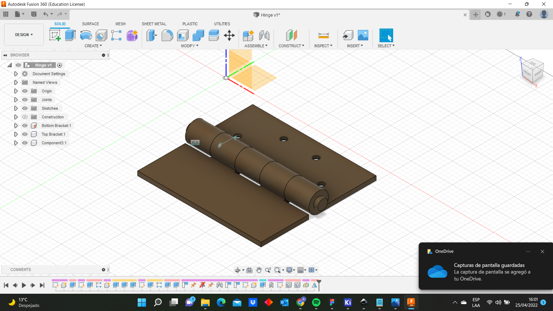
Next stop, Fusion 360 which is a software that it really liked and enjoyed practicing. Once I saw the interface I thought that it was very intuitive and definitely I am going to use it for the next assigments. I wanted to design an objet with articulated movements and finally I choosed a hinge because it is not a complex object but to design it I will need to use many commands. First I sketched a rectangle (120x70mm) then to add depth I used the extrude command and the design become in a solid (Leaf). Here are two images:
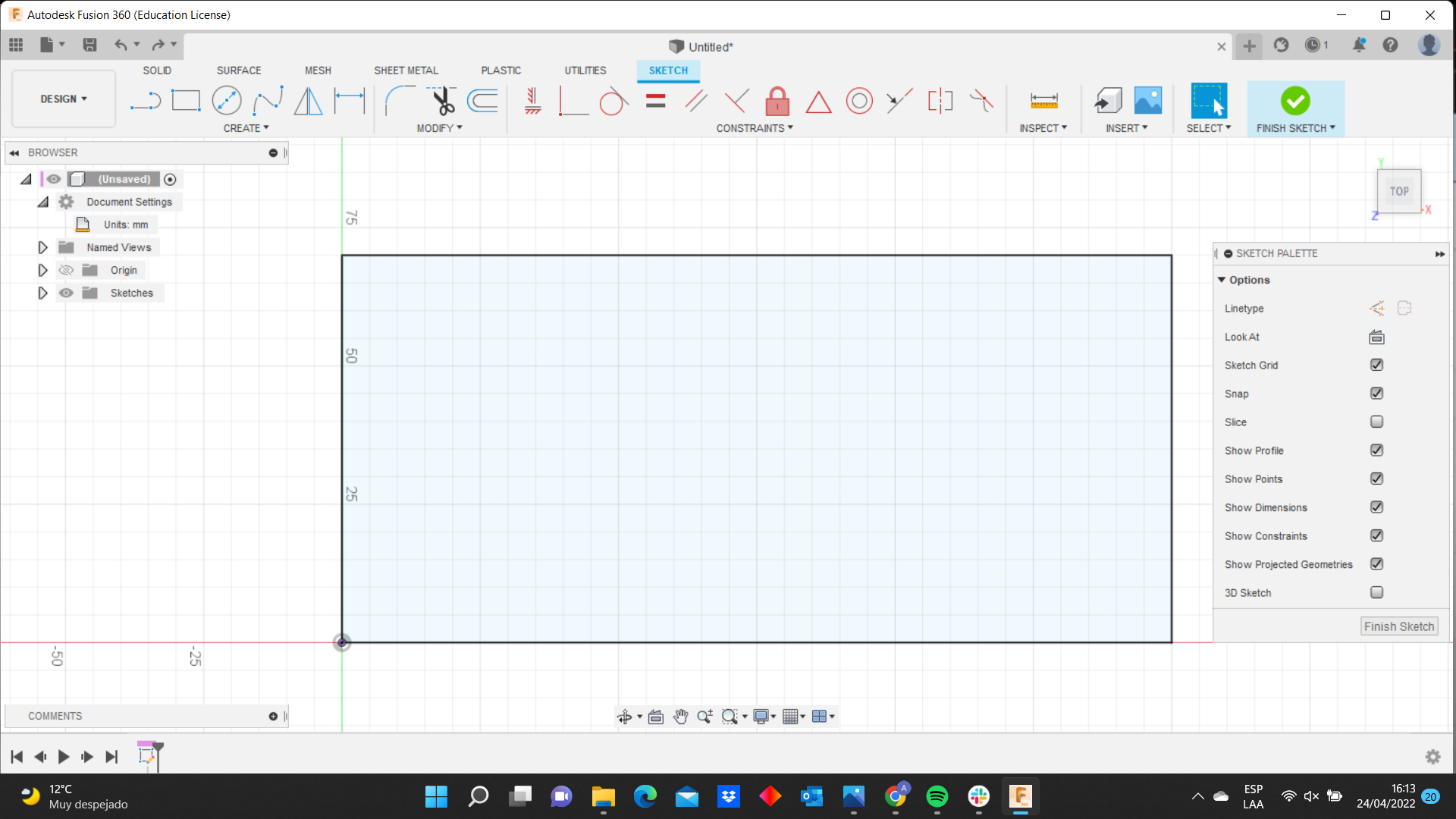
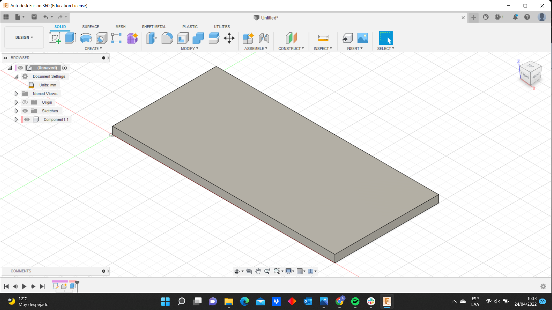
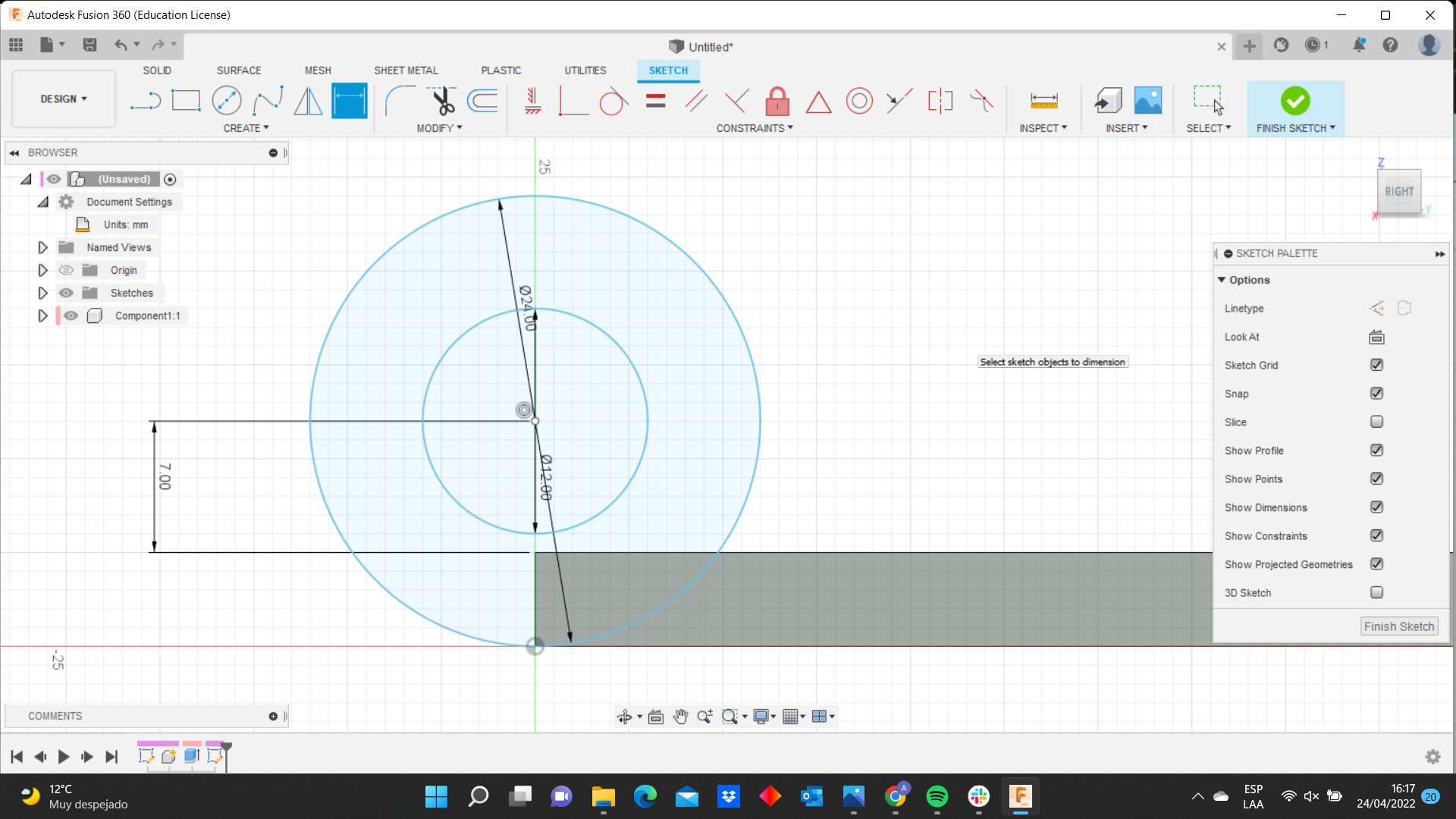
Something that it is important to mention is you can create a component with one or more sketeches. It depends on us how we want to divided our design. For example, I would have created a component only with my rectangle solid but I am going to create 3 components (you will see it in few moments). Afterwards, I designed two concentric circles on one side. Do not complicated as I mentioned the programm is intuitive so you only must select the side and you are going be able to create the polygon or line in the side that you want.
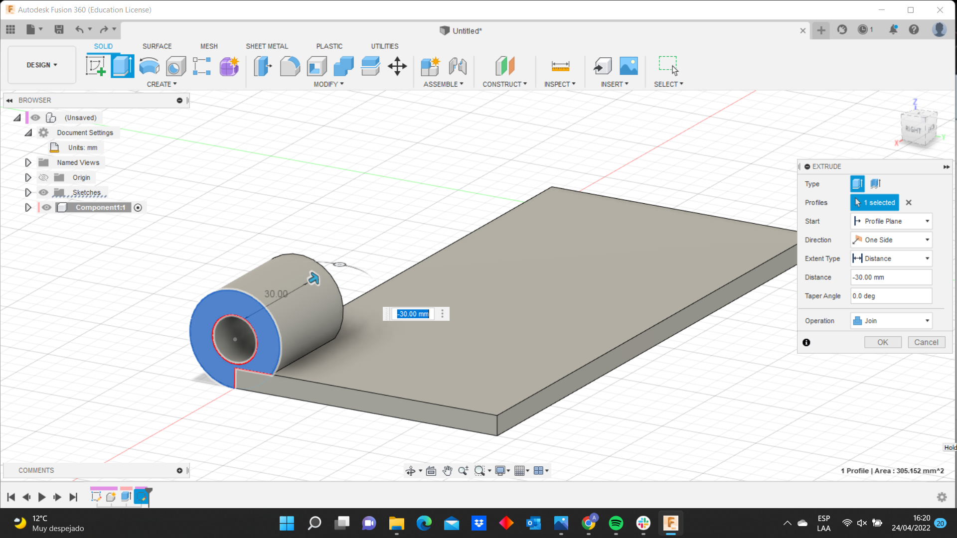
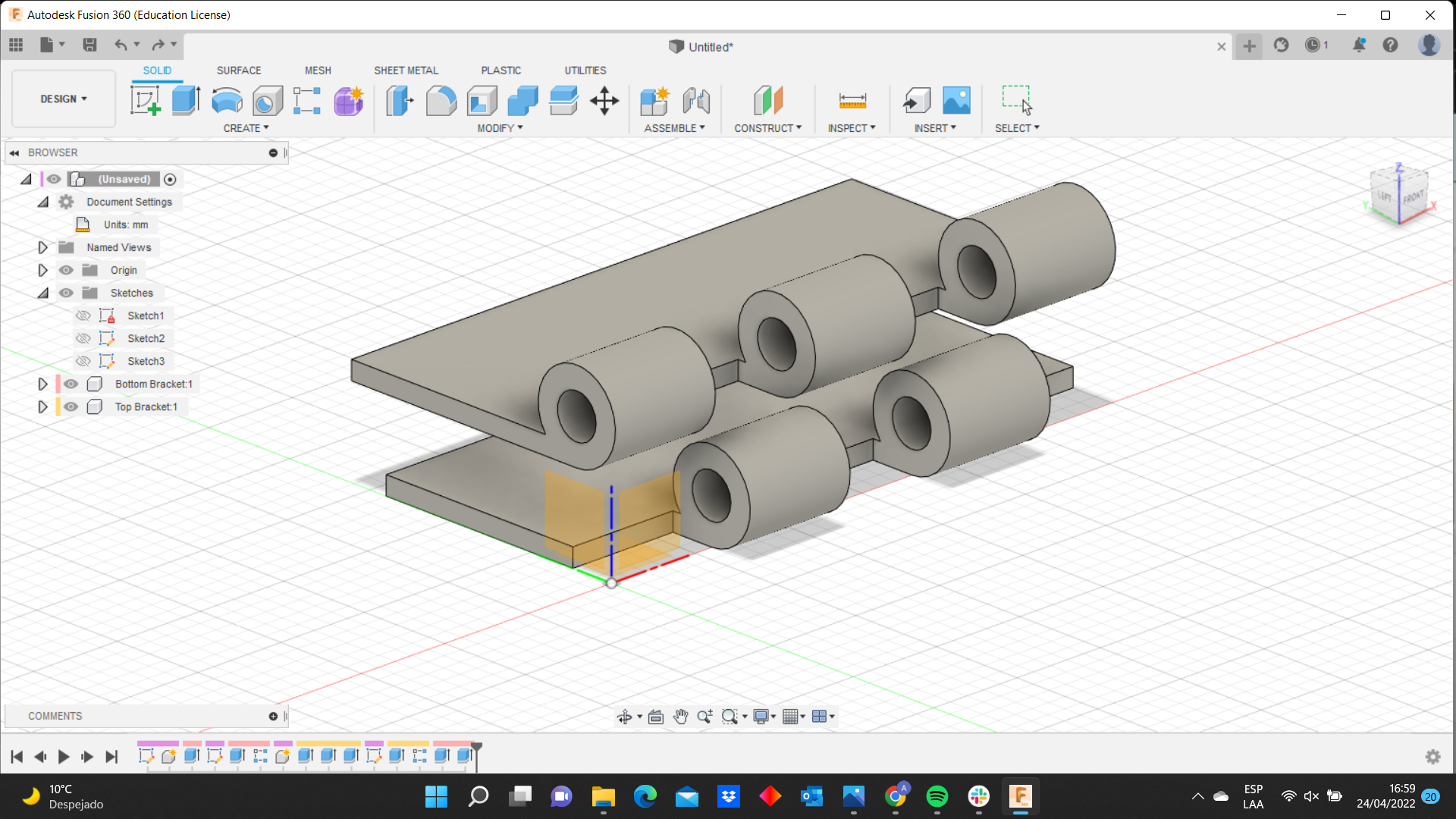
Now, I used the extrude command to create the first knuckle. To create the other ones I used the rectangular pattern. At the beginning I was designing 5 knuckles but then I realized if I wanted to use the joint command that allows me to show the hinge movement, I needed to create 2 components: one with two knuckles and the other one with three.
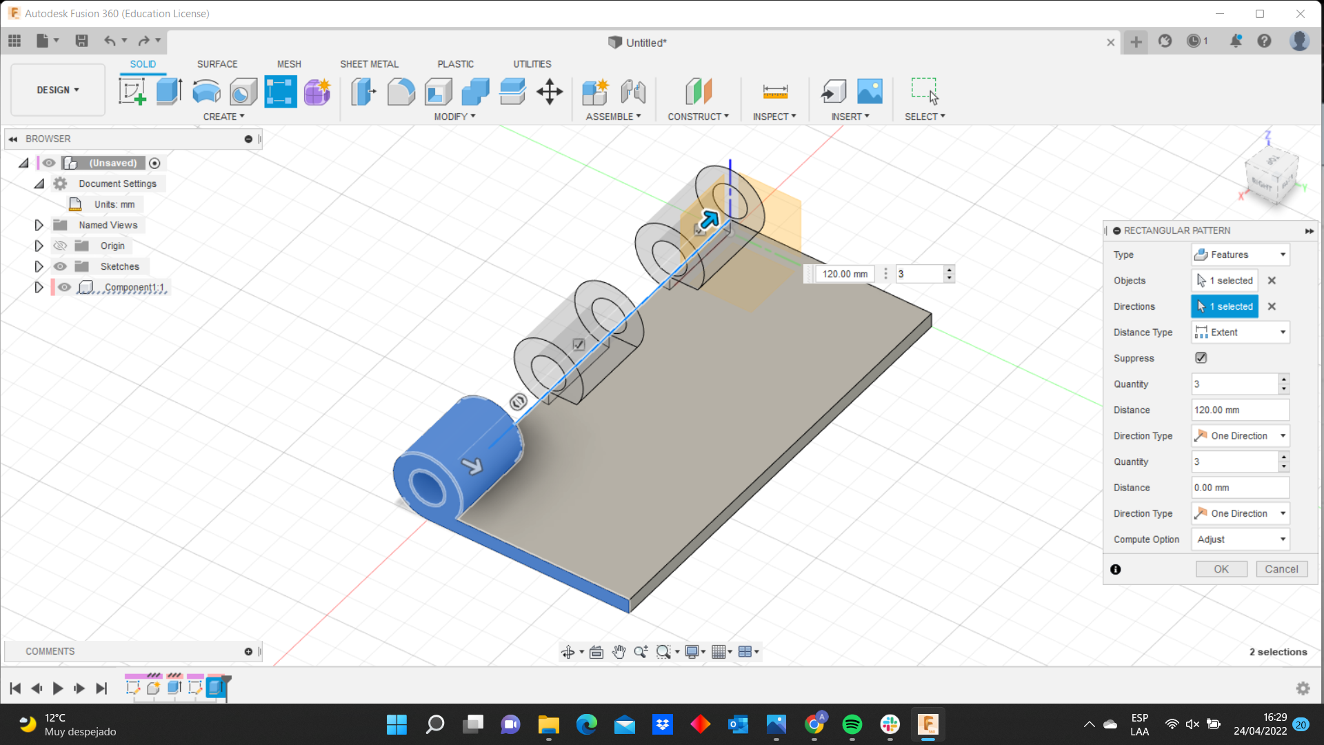
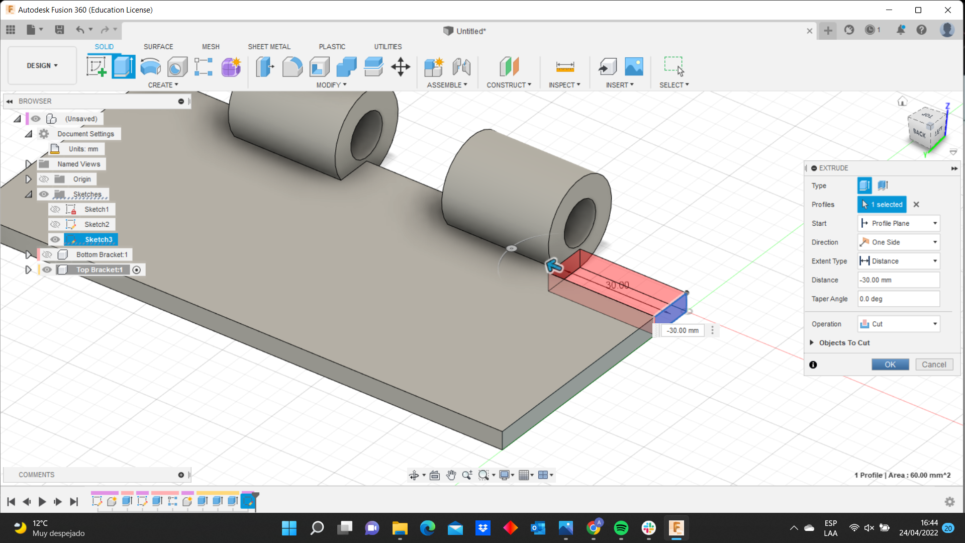
As you can see, I create the bottom bracket (which has 3 knuckles) and the top bracket (which has 2 knuckles). To create the two knuckles I used the extrude command but I changed the start in order to design the solid in other point, as you can see in the picture:
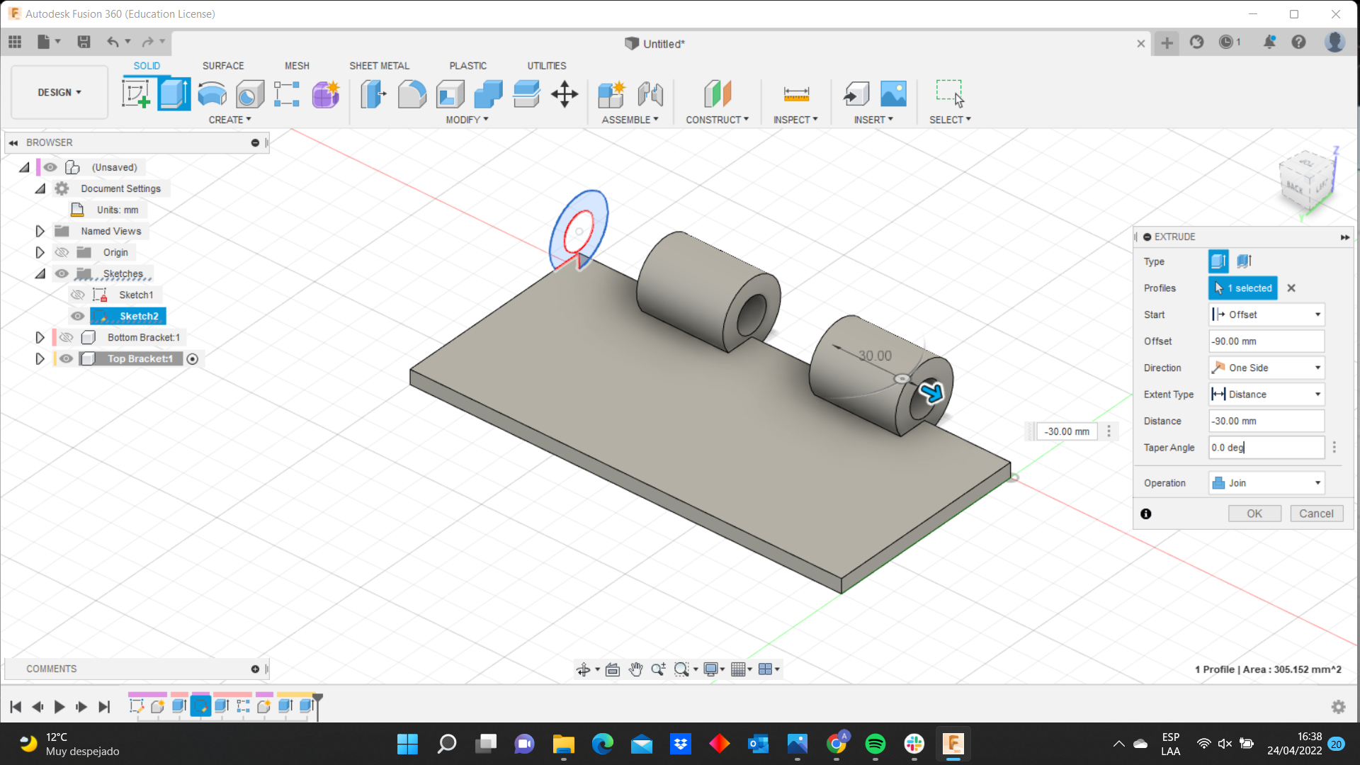
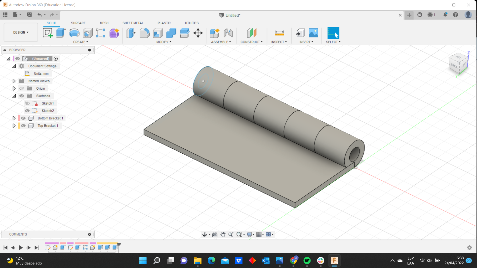
Afterward, I needed to cut a solid rectangle next to the knuckles. I sketched a rectangle on the base and I used the extrude command. Later, I used the rectangle pattern to replicate those solid rectangles in all the leaf. I repeated the same process in both leafs.
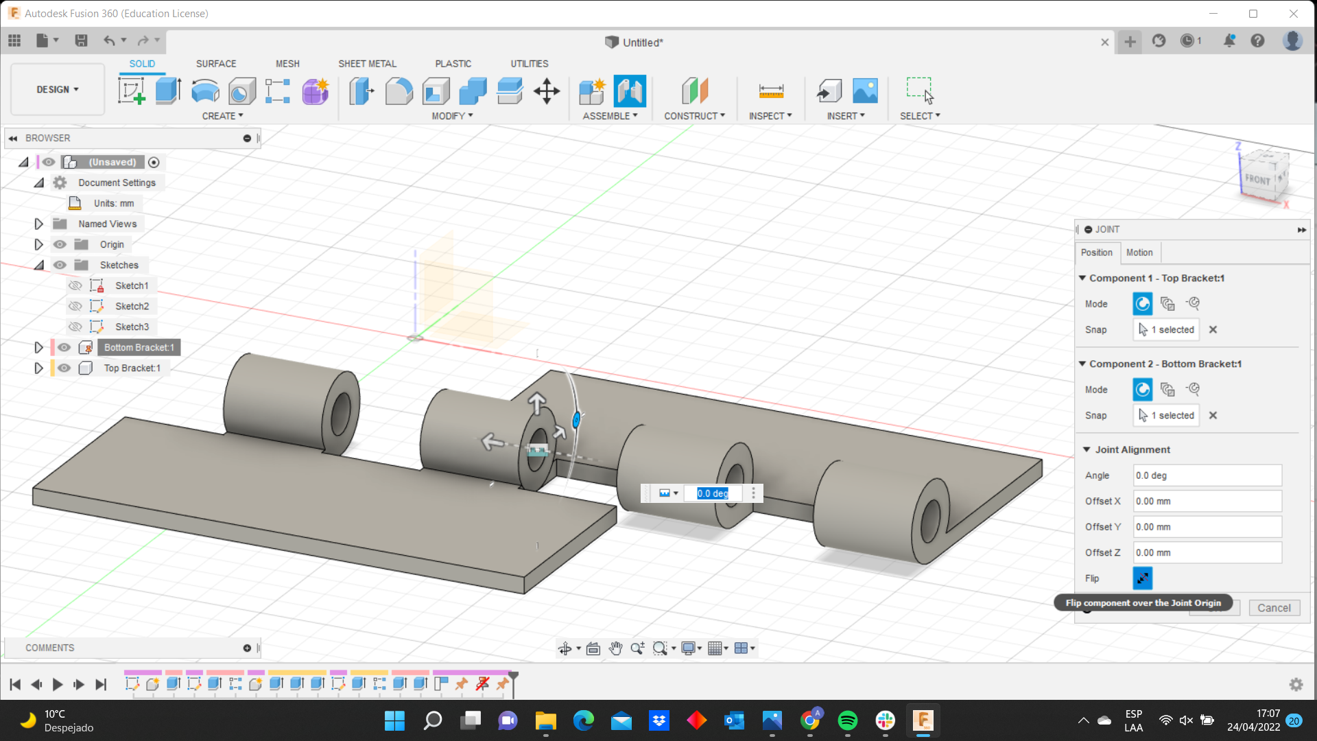
I have my two main components so I needed to separate and put them on the ground to use the joint command (by the way to find this command you must go to assemble>joint). It is simple use this command because you only select the components and then you can see in the software a simulation and you can change wherever you want.

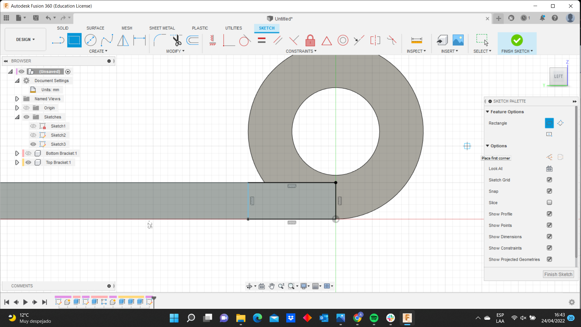
It is important to create the holes for the screw and we can do that in the hole command. Look this image:
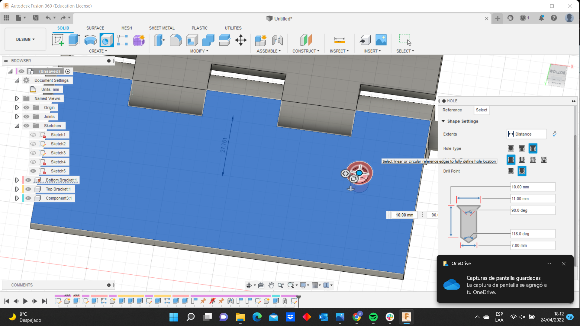
You can define the screw parameters and then replicate it with the mirror command.
Finally, I used the render functions to simulate the hinge in bronze.

 This a video of my final design on fusion 360:
Hinge Movement from Angel Erazo on Vimeo.