7. Electronics design
Indidual Assignment
For this week we have to design our own PCB. We have to redraw the echo hello-world board and add a LED and button, at least. The lecture was very interesting and the instructors gave us a tutorial for using Kicad. First, we have to download the fab components libraries and the components footprints to get a design correct with our components. Also, these componets will be used during all the fab academy. So, we must start!
Schematic
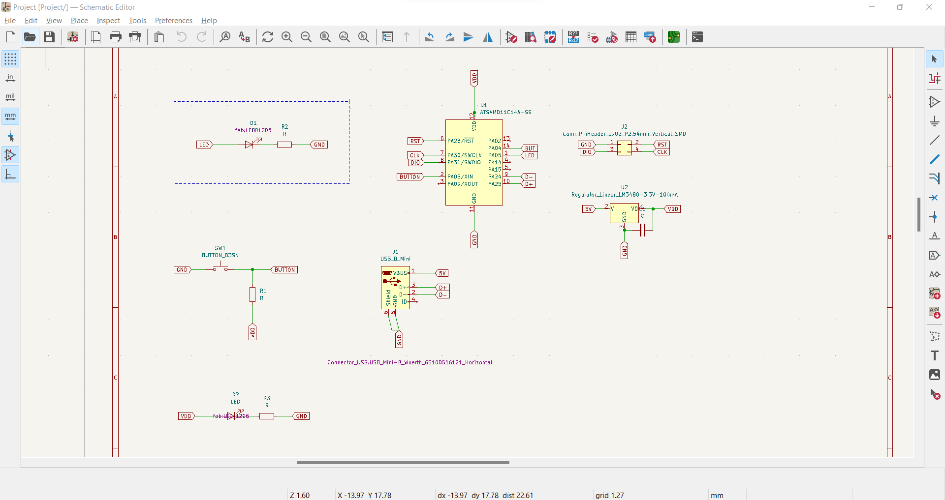
When we are creating the schematic, we are defining all the components that we are going to use and the connections between them. I have chosen the following componets:
- 1 Voltage regulator with its capacitor (1uF)
- 1 LED that shows us if the connection to the computer is right or wrong with 1 resistor (100Ω)
- 1 LED to the microcontroller that can be programmed. Also, with 1 resistor (100Ω)
- 1 button connected to the microcontroller to be protect and it needs a pull-up resistor (1KΩ) to protect it from little currents or bouncing.
- 1 Mini USB connector for durability
- 1 Pin 02x02 connector
- ATSAMD11C microcontroller
This is the final result:
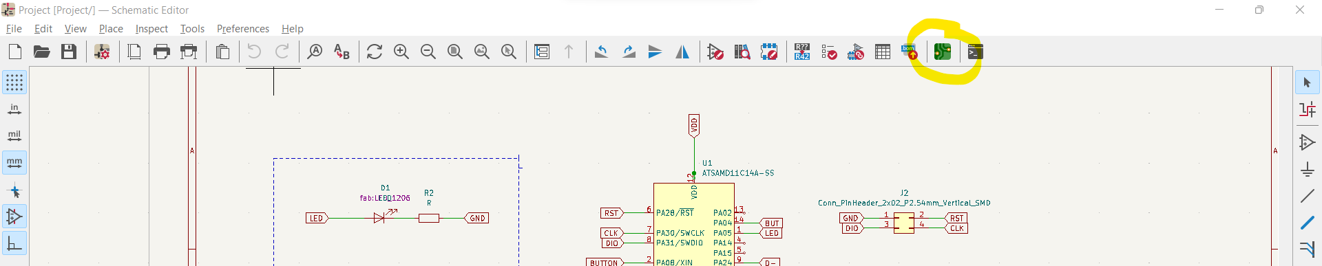
Once we finish the schematic, we can move to the other step which can be kind of frustating at the beginning.
Routing the board
Something important to mention is that on Kicad 6.0 we have an option that generates a PCB editor window, automatically.
 Here, we start with the routing. First, I set up the design rules and constraints for my board. In the PCB editor window we must following these instructions:
- File->Board Setup
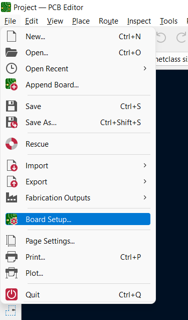
-
Design Rules->Net classes
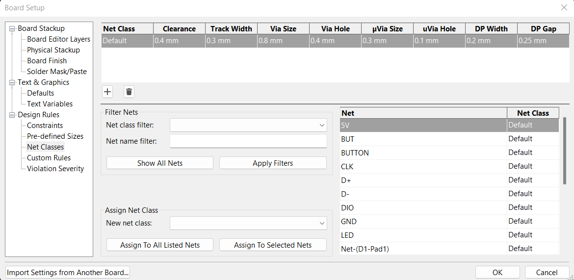
-
I set up the cleareance=0.4mm (distance between 2 paths) and track width=0.3mm Now I can start with the routing. This was the first time that I have done that and as I mentioned it can be very frustated however you realize that is just a matter of practice.
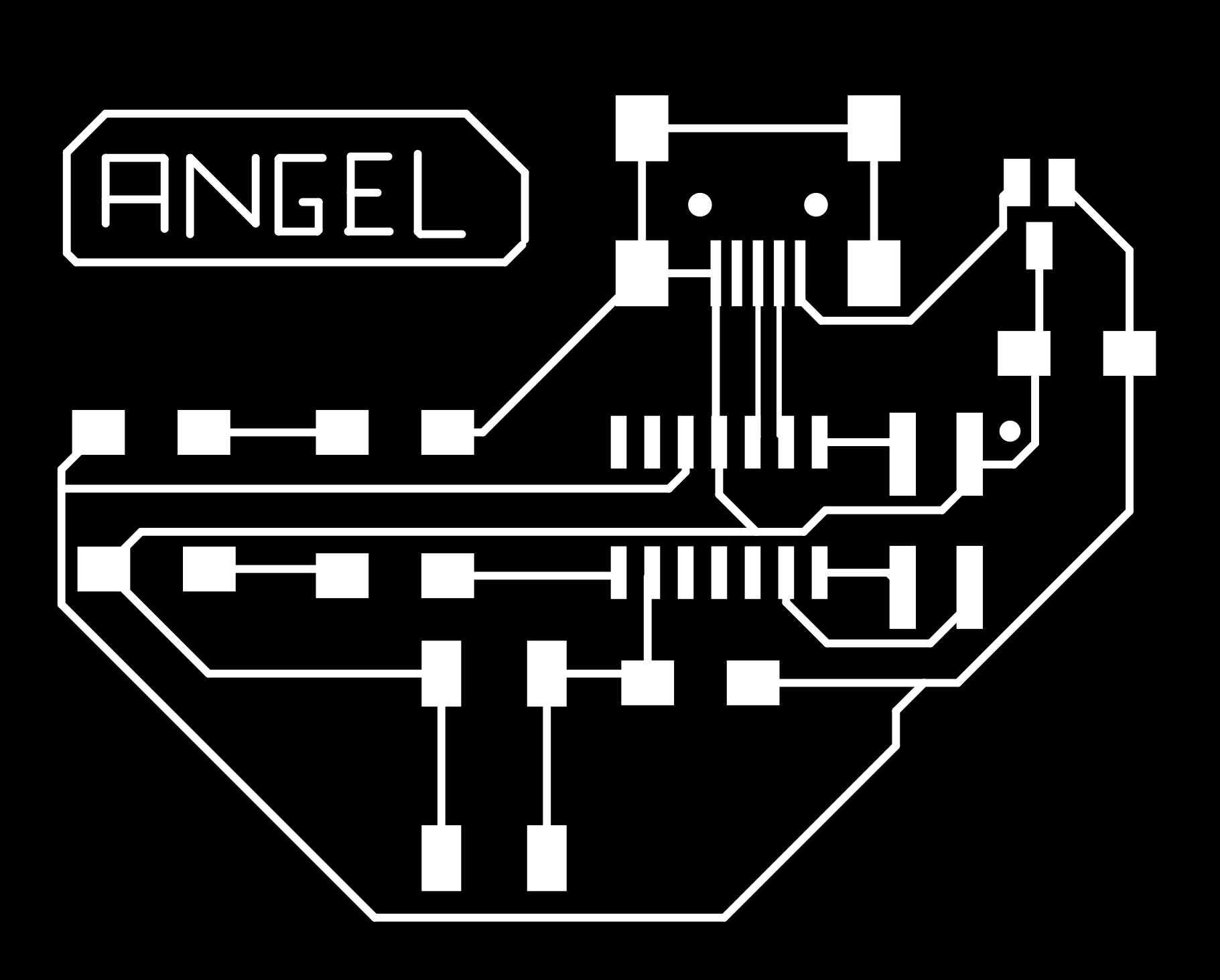
After all the afternoon, this is the final result:
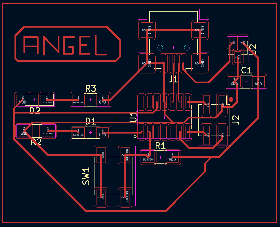
Now, we have to export the files as SVG.
Inkscape
Now, we generate the PNG file that we are going to use for modsproject. We must follow these steps:
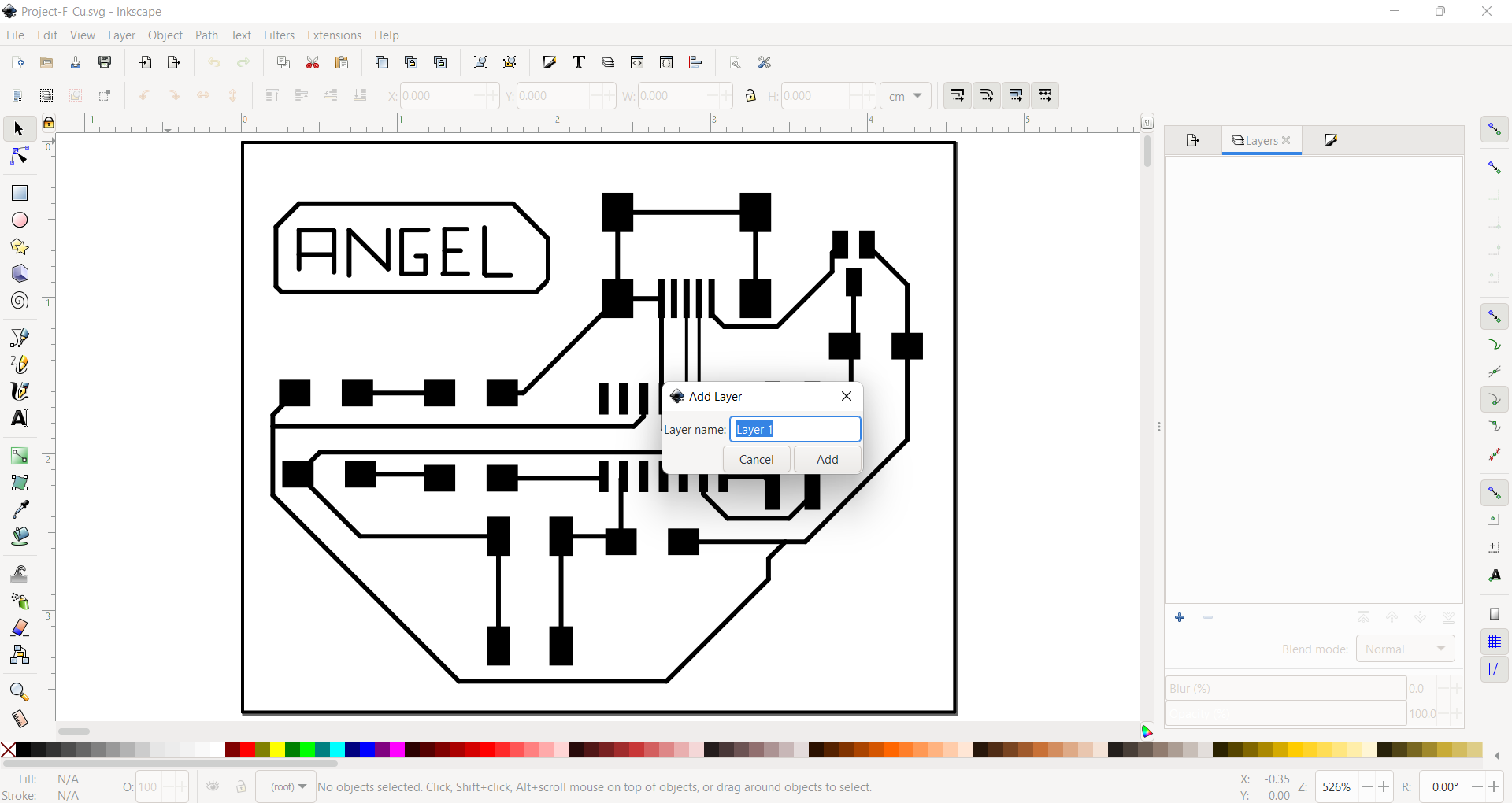
1.- We have to import the SVG file to the inkscape.
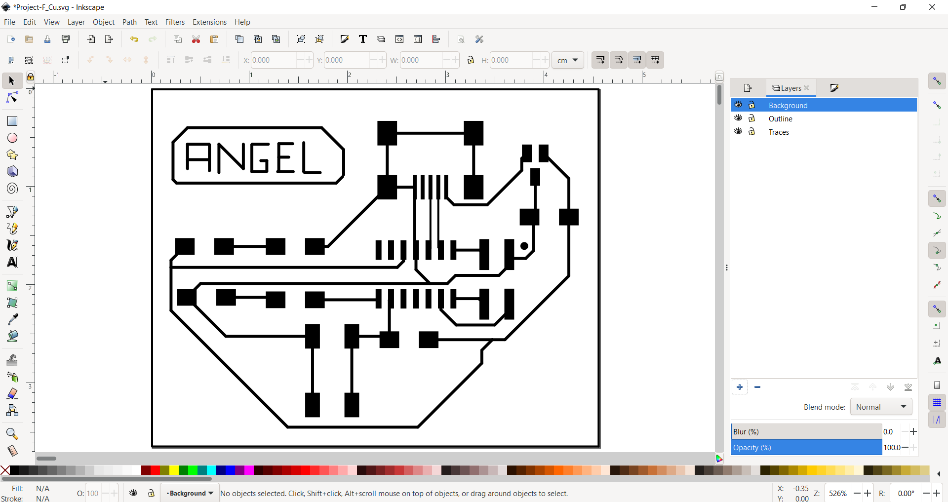
2.- We create the layers: Background, traces and outline.
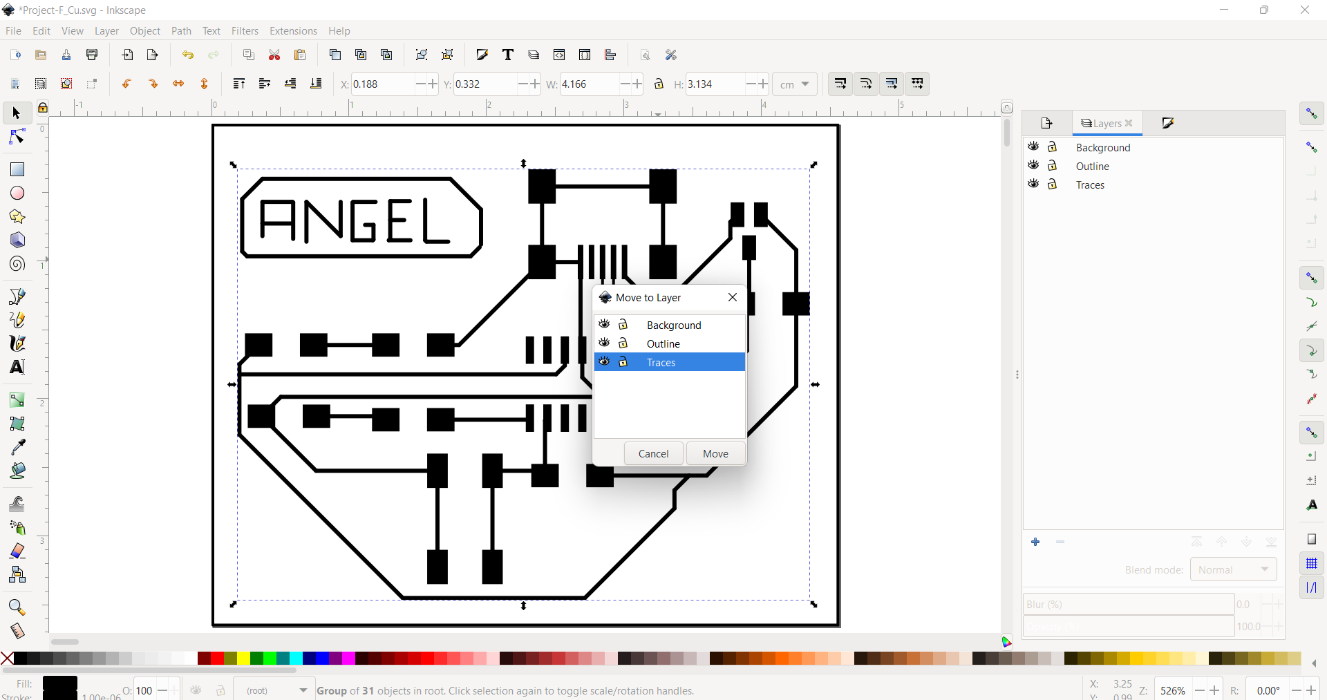
3.- We select the traces and move them to the traces layer.
4.- I did the outline with the draw bezier curves command. I moved the outline to the outline layer.
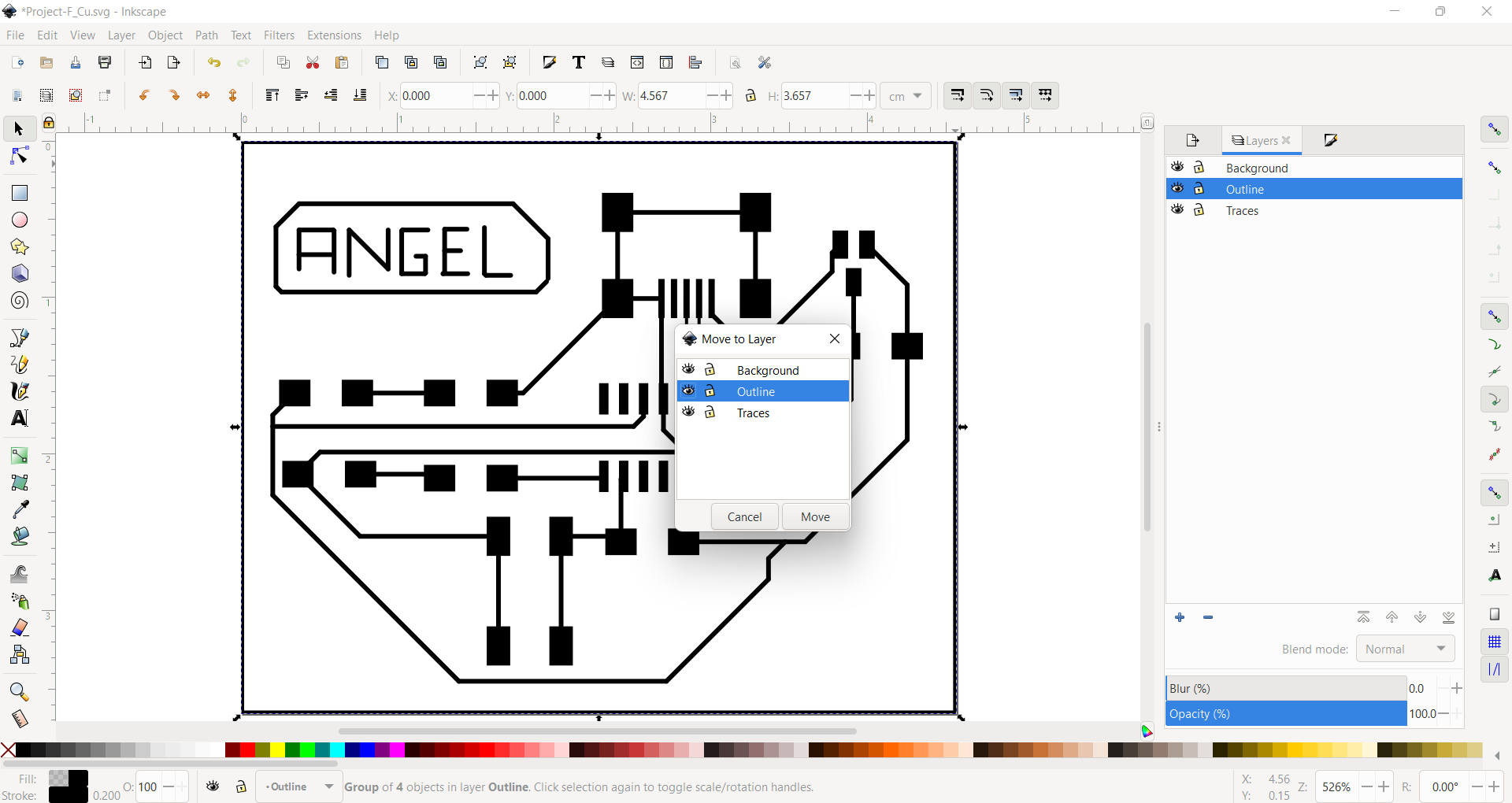
5.- We create a rectangle to move it to the background.
6.- We select all the traces and we fill the object in white and the strokes have to be in white.
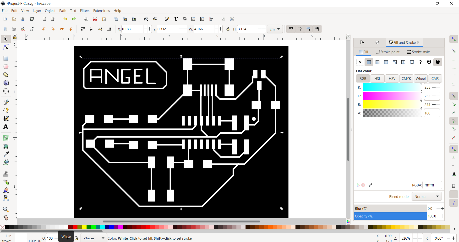
7.- Afterwards, we can change the outline and fill the stroke in white.
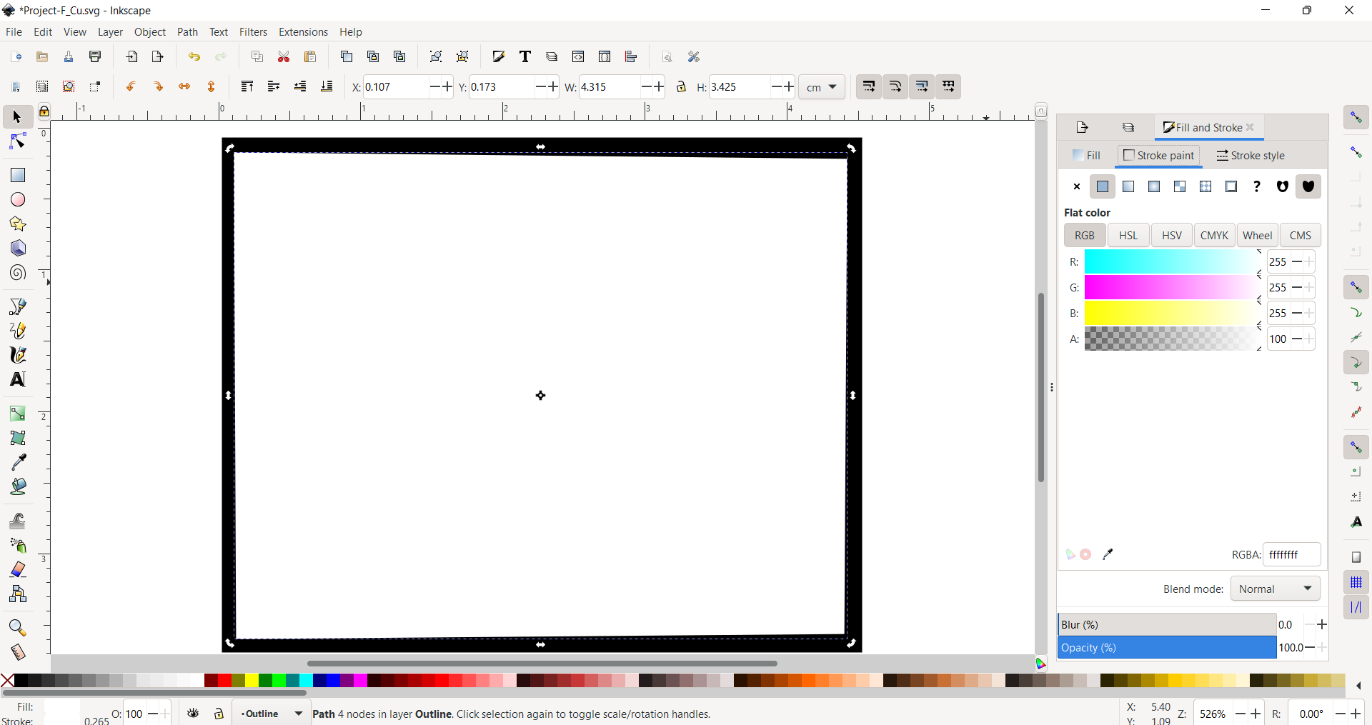
8.- Now, we can export the files as png, we must remember that we need two generate two file: traces and outline.
This is a picture of the pngs:


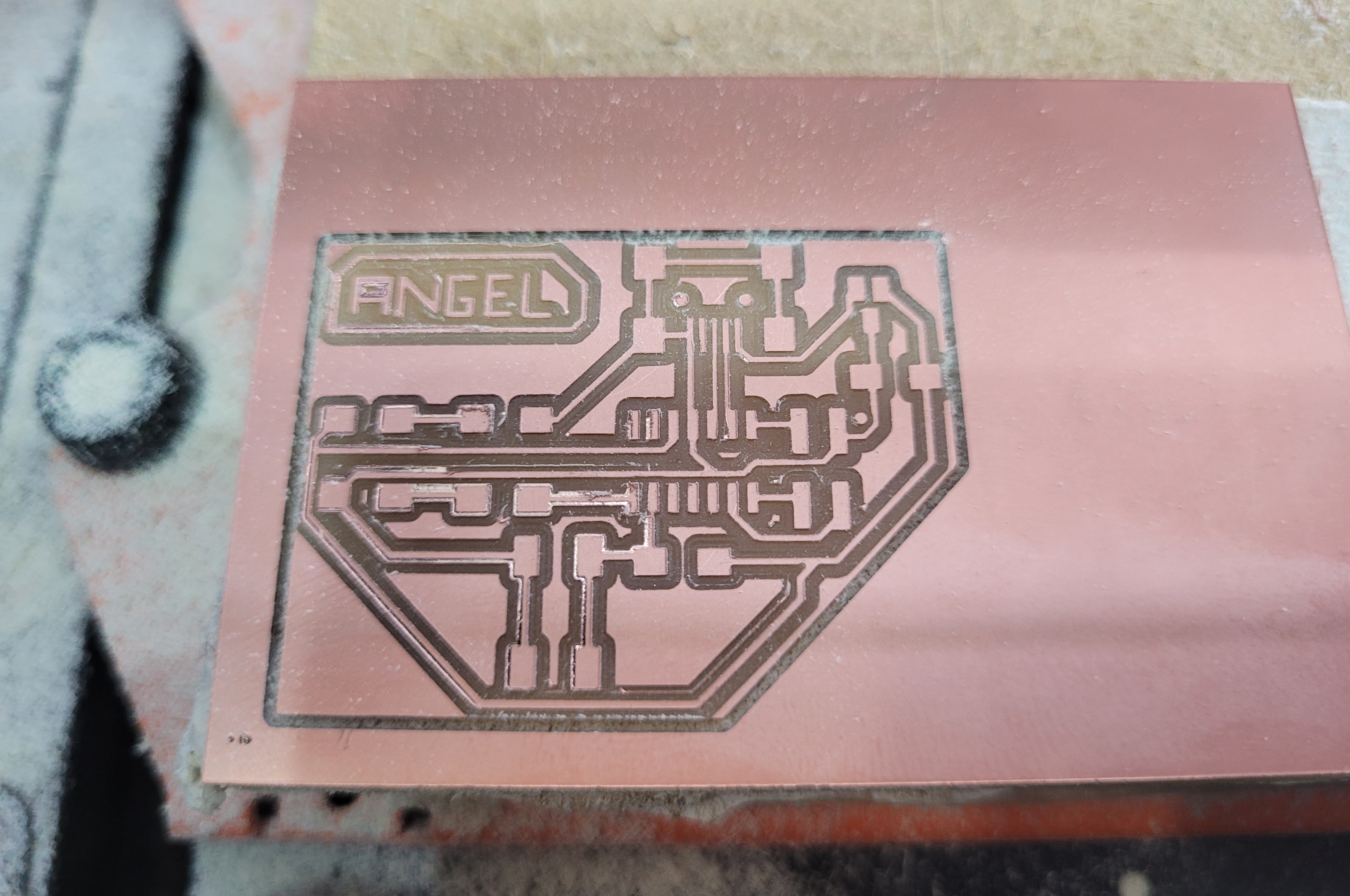
Milling the board
For this step, I had to do the similar process that we have done in week 4. First, I generated the G-code on Modsproject. You can take a look of some modsproject screenshots:
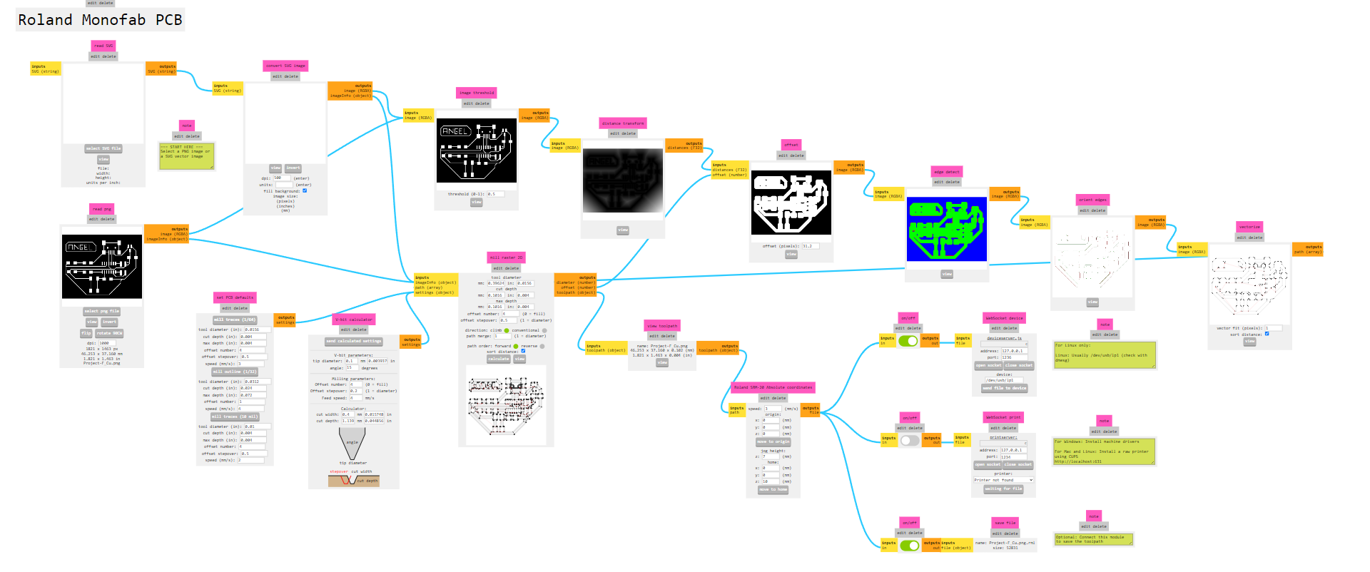
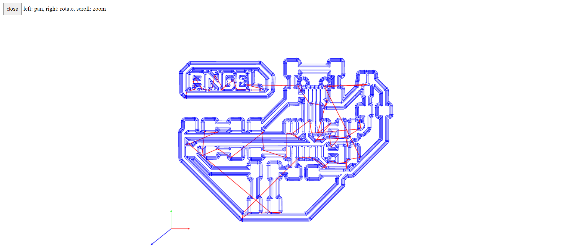
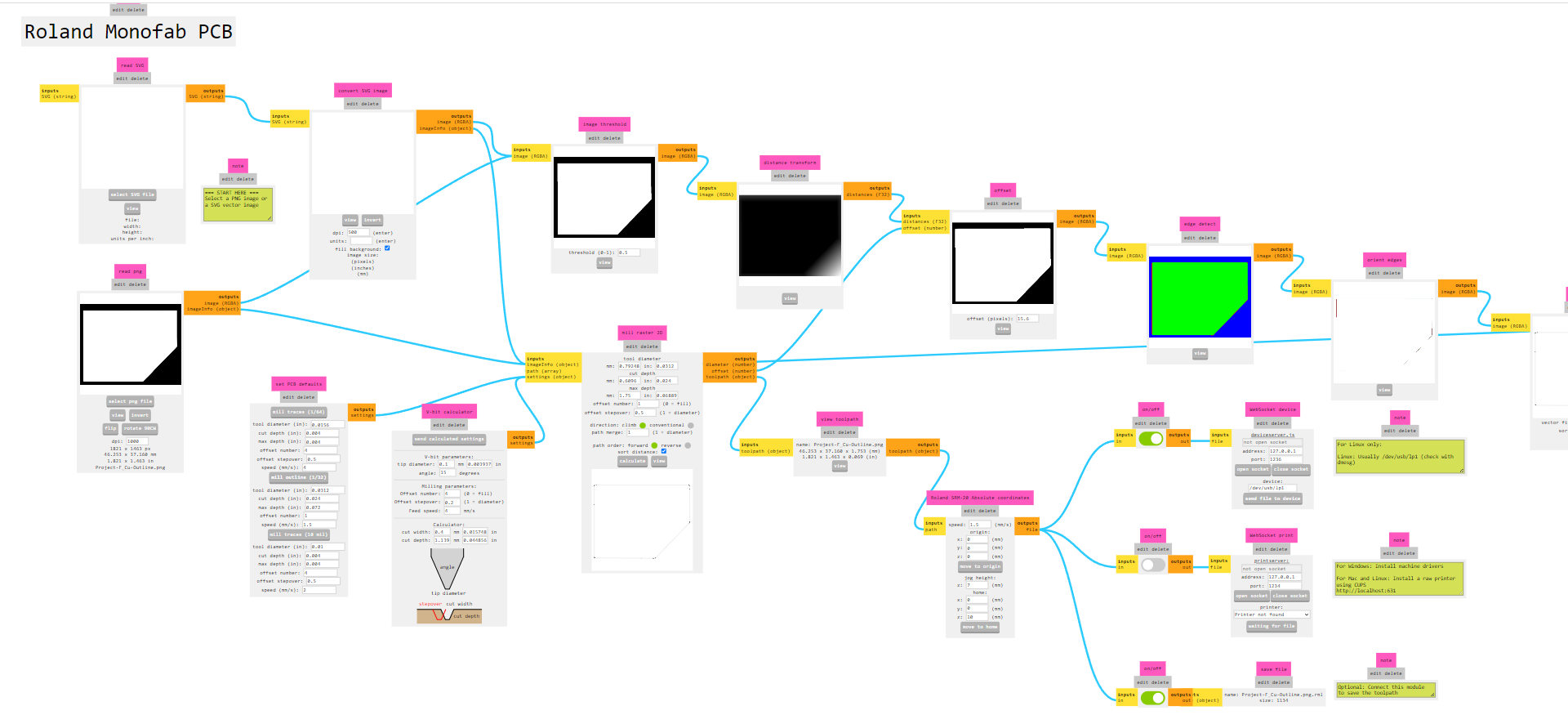
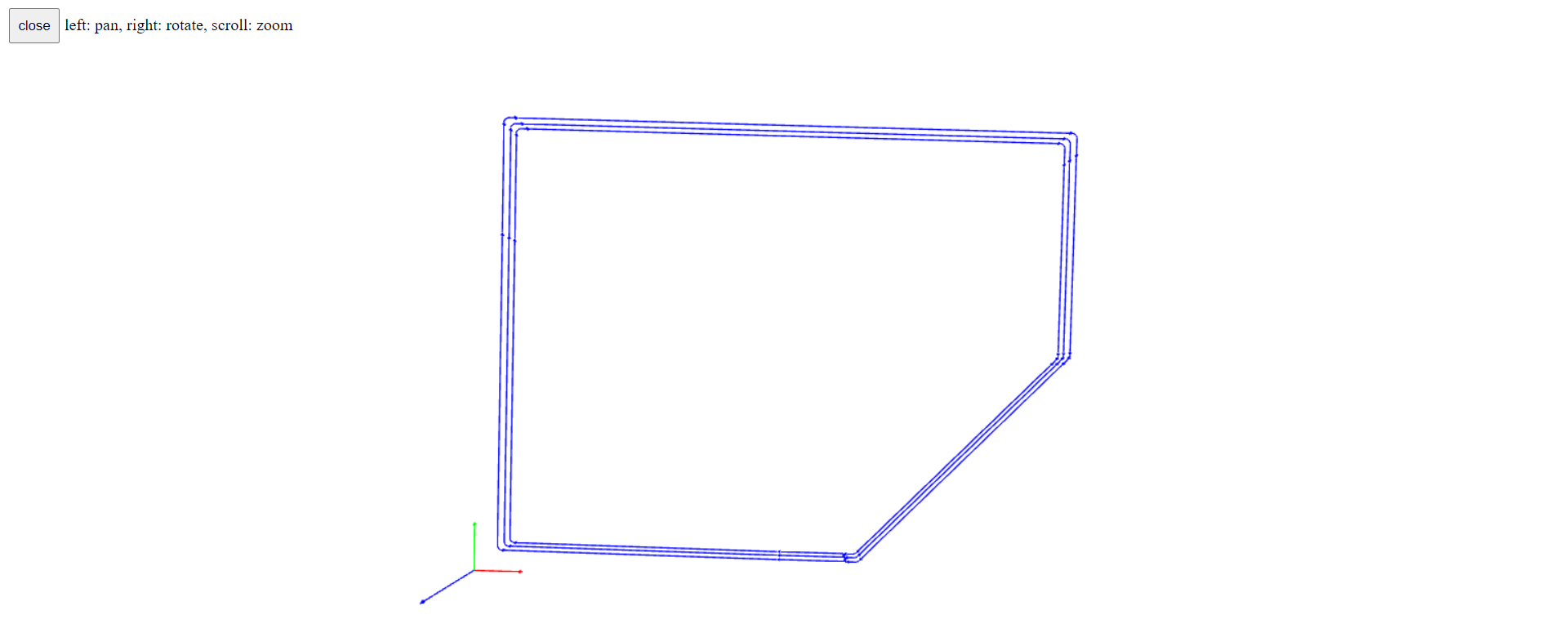
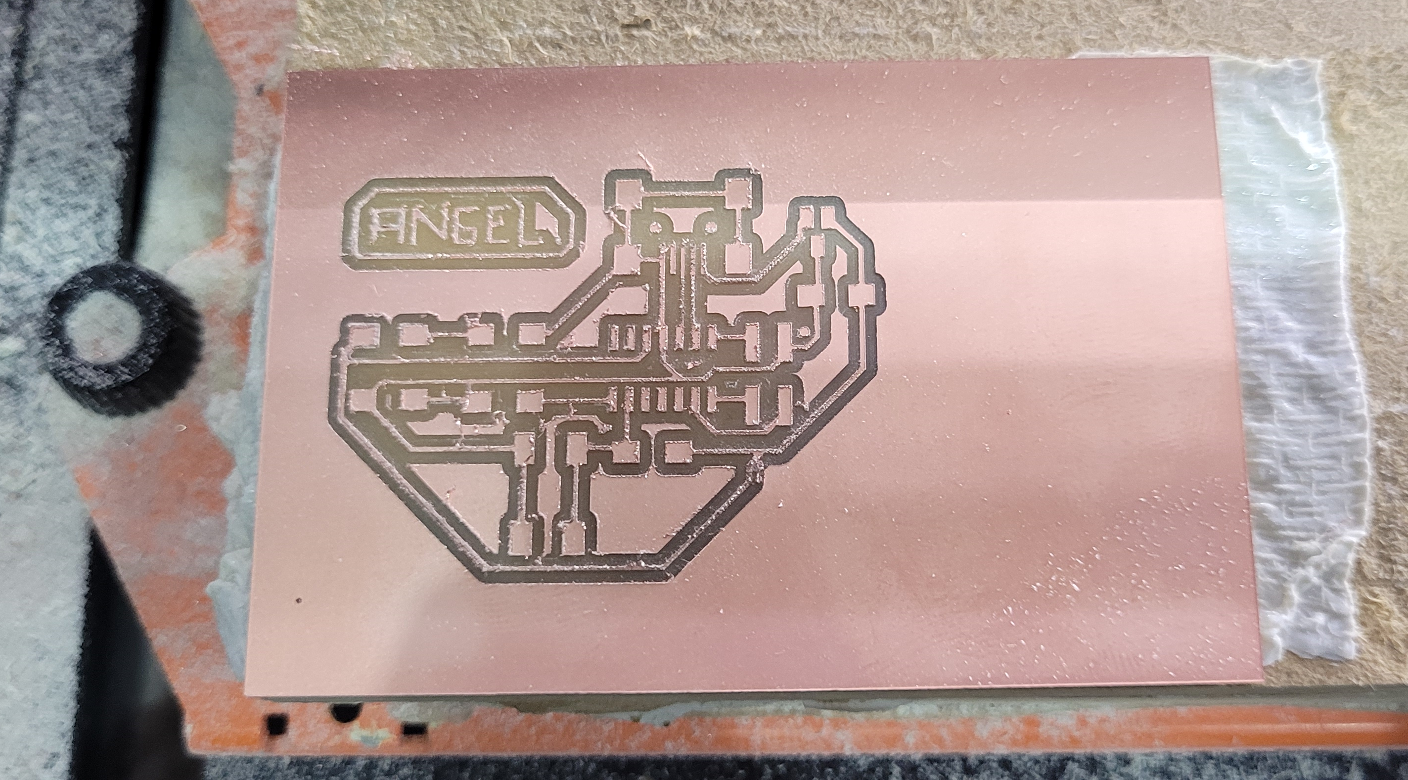
Then, I went to the CNC Machine and for the traces I used the 1/64 inches mill and the outline with the 1/32 inches. Here I have some pictures of the process:

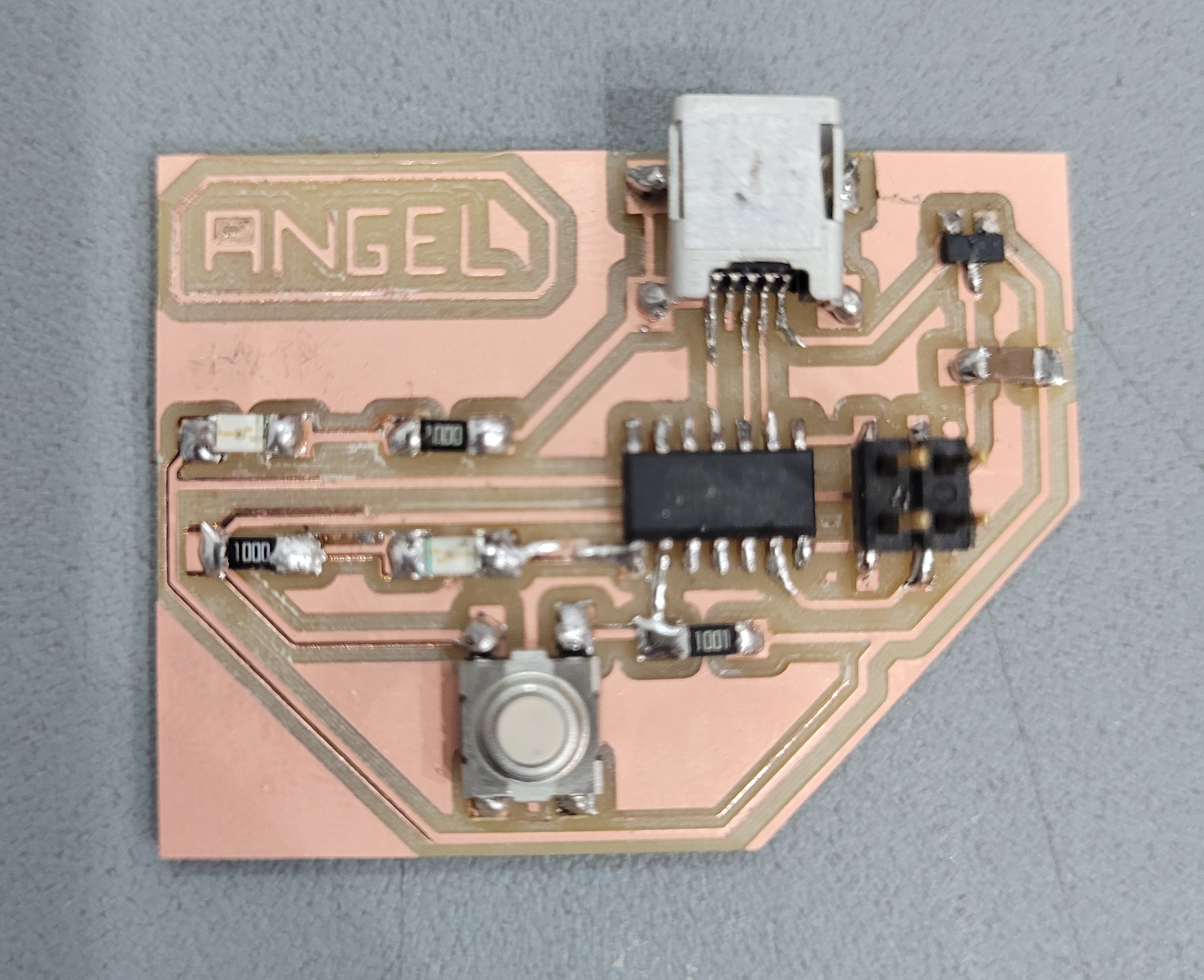
Soldering
I really enjoy this part! Even when I made a mistake because I did not realize that I had not soldered the connections between the Mini USB and the microcontroller. That is why, we always must check the board and clean it before soldering.
Programming the board
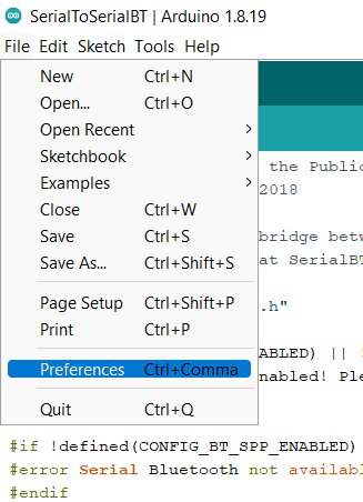
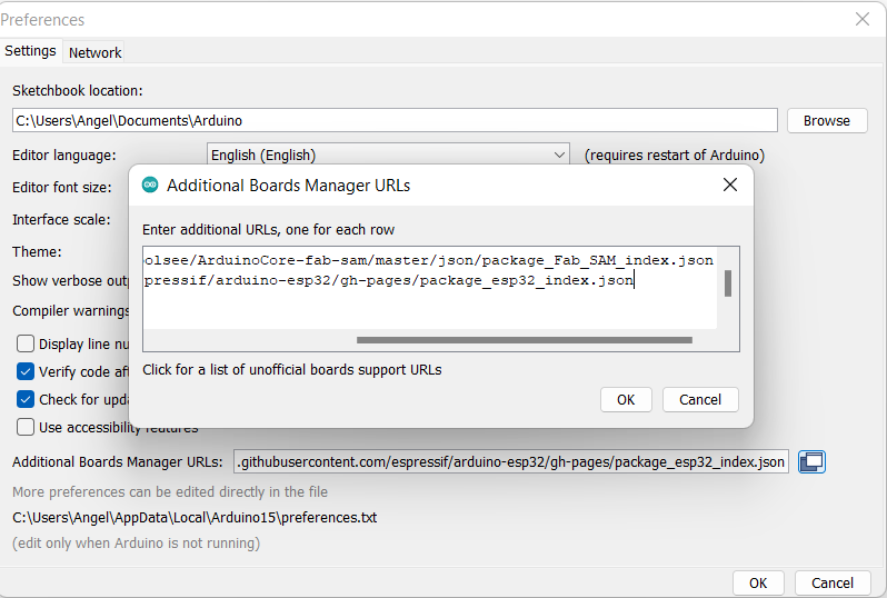
The first thing that I did was to download Arduino IDE. Then, I need to get the configuration ready to use a SAMD11C14A with Arduino. To do that, in Arduino IDE: 1.- File -> Preferences -> Additional Boards Manager URLs I copied this URL: https://raw.githubusercontent.com/qbolsee/ArduinoCore-fab-sam/master/json/package_Fab_SAM_index.json.
2.- Tools > board > board manager. In the browser I typed “fab”, I can see the Fab SAM core for Arduino by Fab Foundation and I installed.
3.- Finally, with the board connected, it is important to burn the bootloader to set your configuration to the chip.
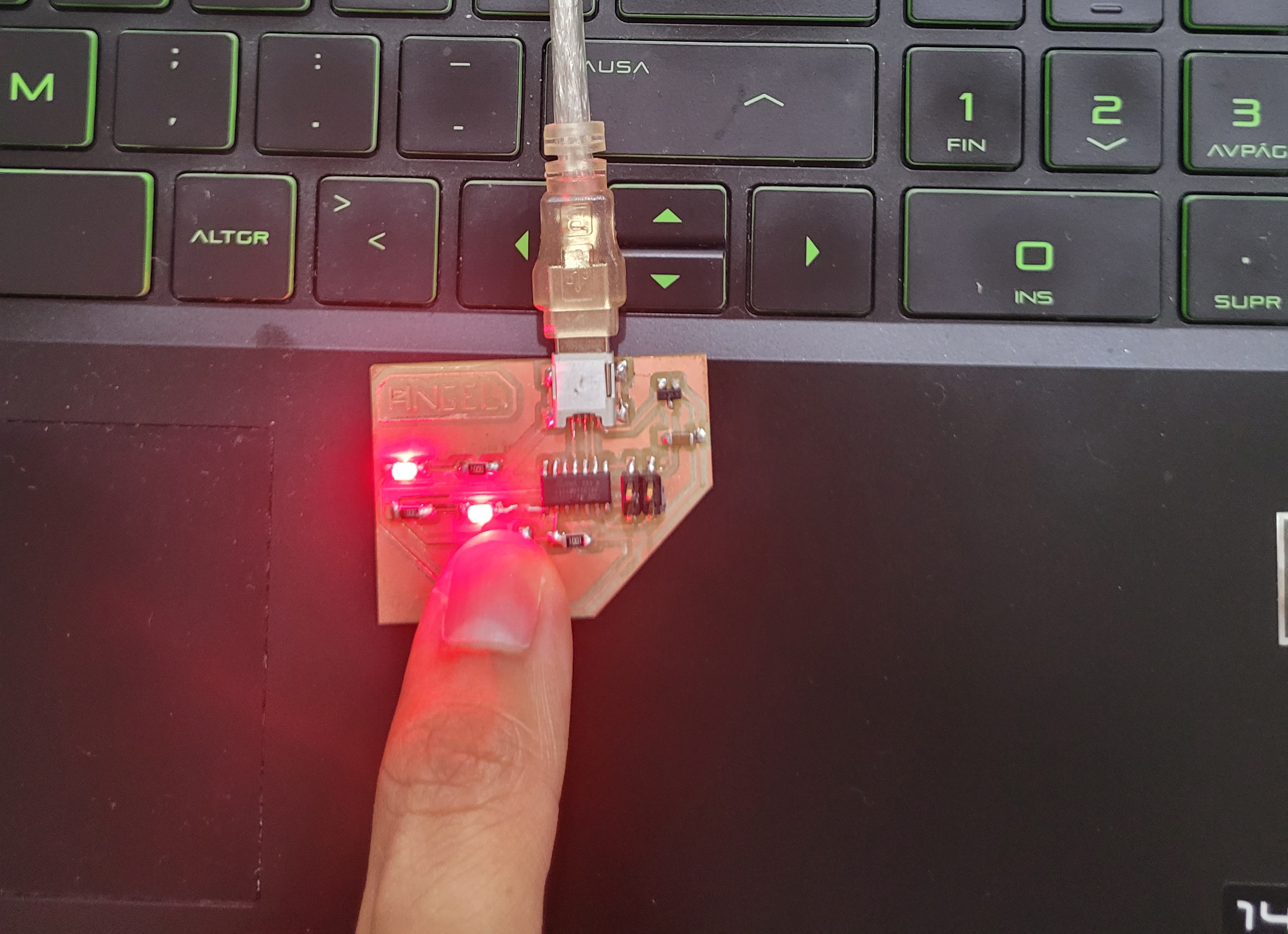
Now I can program the board. I did a simple code where the LED will turn on when I press the button and turn it off when the button is not pressed. This is the code:
void setup() {
  // put your setup code here, to run once:
  pinMode(8, INPUT);
  pinMode(5, OUTPUT);
}

void loop() {
  // put your main code here, to run repeatedly:
  if (digitalRead(8) == HIGH){
    digitalWrite(5, LOW);
  }
  else {
    digitalWrite(5, HIGH);
  }
  delay(100);
}
This is the finalresult:
Video-Programming from Angel Erazo on Vimeo.
Group Assignment
Here is the link.