4. Computer controlled cutting
Individual Assignment
The assignment for this week is create something that has been designed with parametric constructions to be cutted on the laser cutter machine. Then, for the vinyl cutter I want to design a nice sticker. Let is start!
Designing on Fusion 360
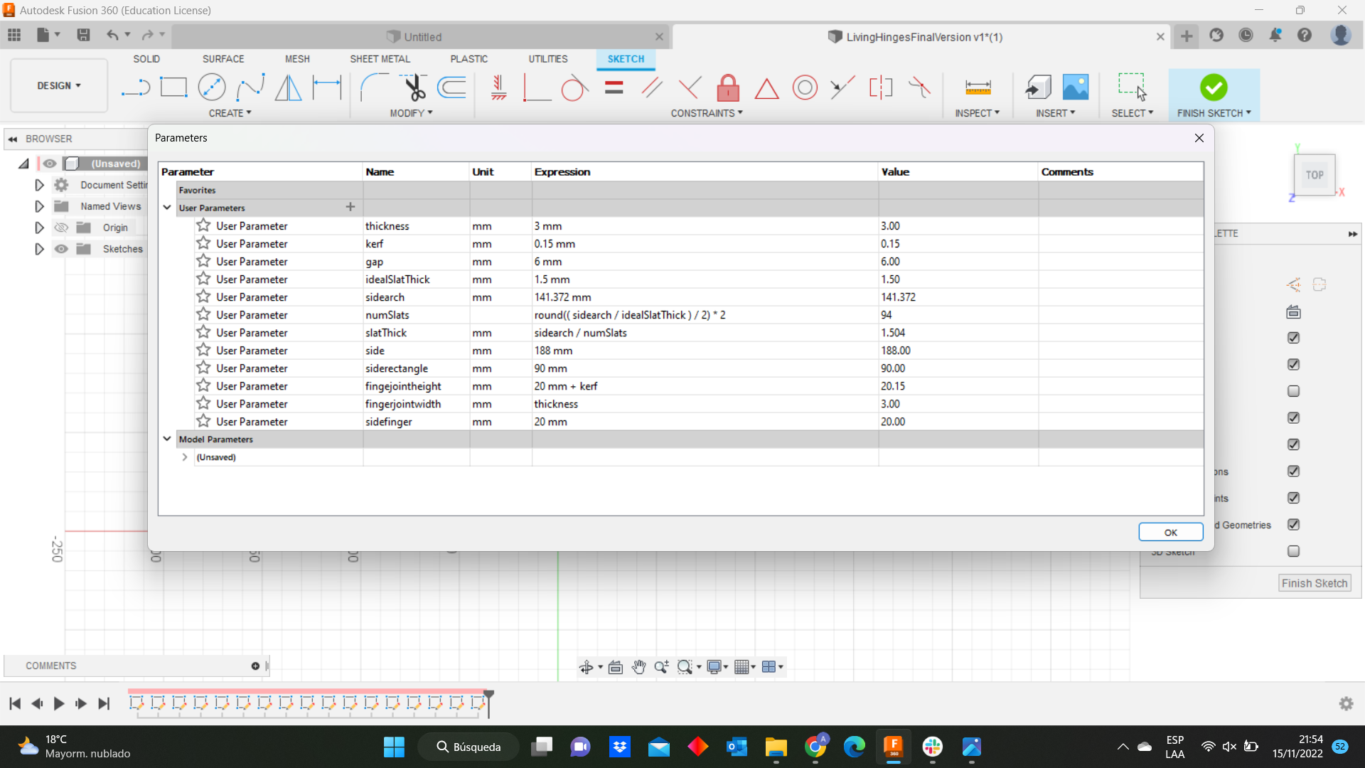
I thought to design an object with living hinges and besides I wanted to use it as box. Therefore, my design will have 3 pieces. Before to start with the design, I need to do the parameters definition so we are going to create a parametric design which is very useful because we do not know the exact tolerance and changing it with only one number. Therefore, if you wanted to change your design is as simple as changing those numbers. The parameters were defined on Fusion 360 and it can be changed and showed immediately on the design. You can see what parameters I defined in the following picture:
Then, I sketched a rectangle then I drew an arc using the arc command with the option 3-point arc . Here, There is one image about what I am explaining:
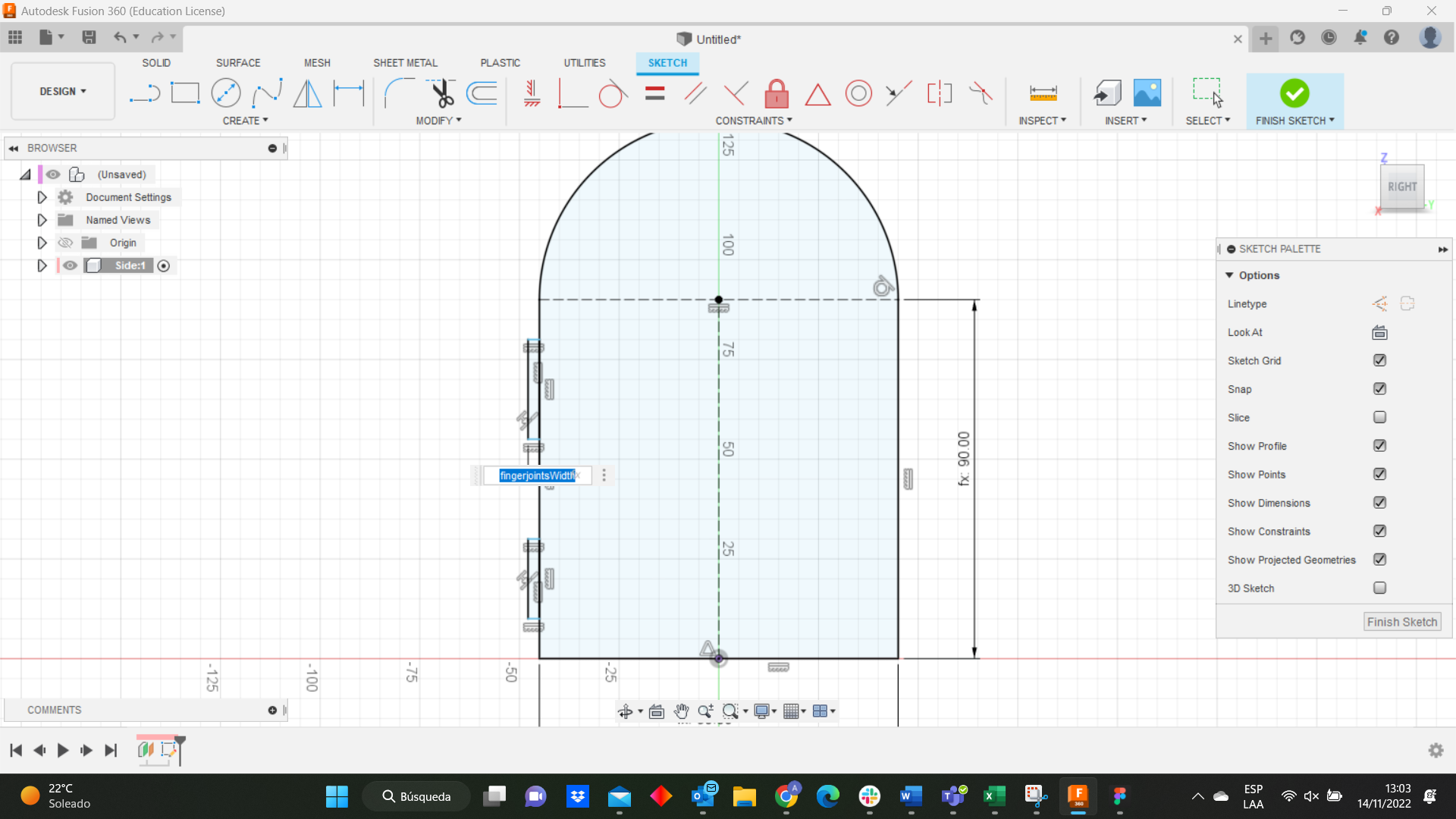
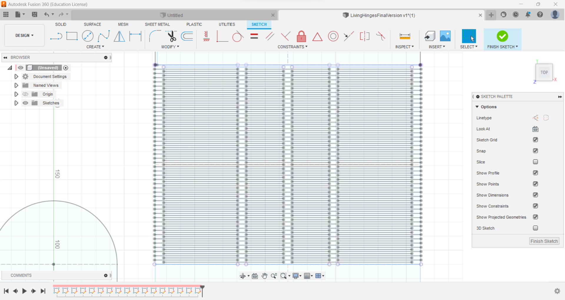
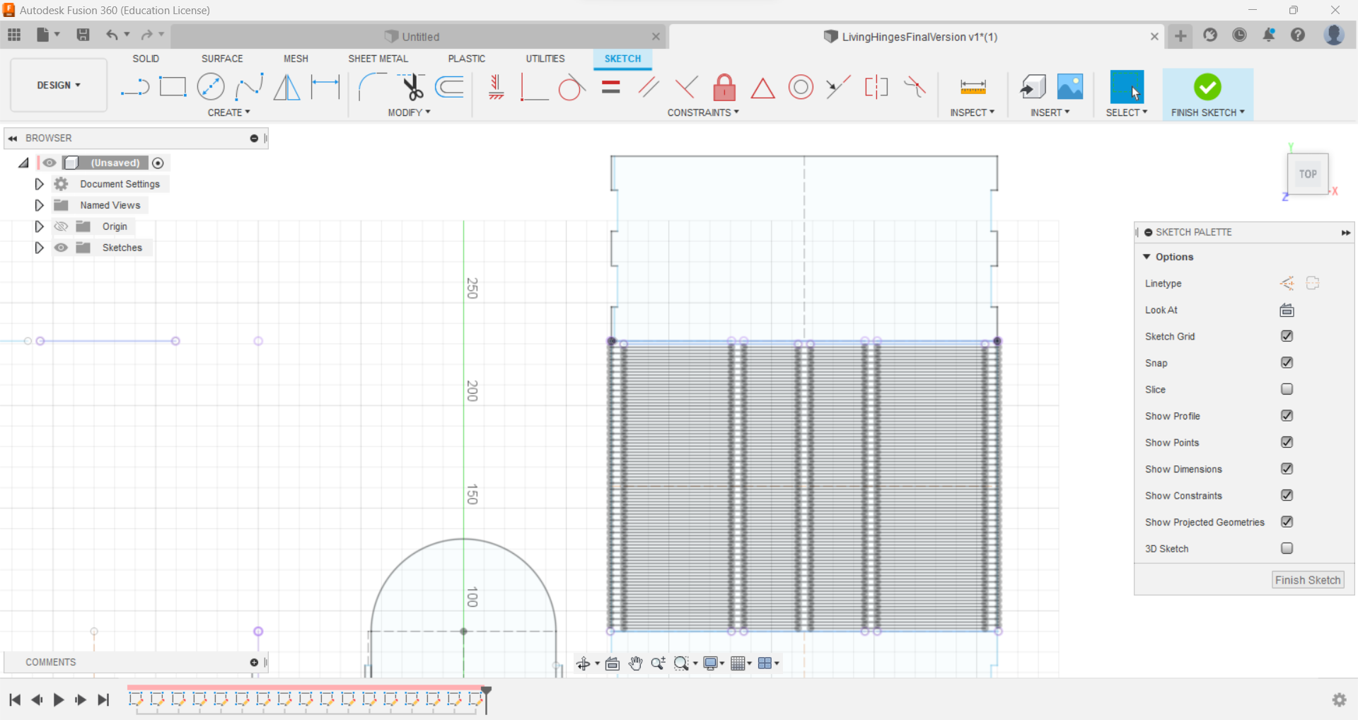
Afterwards, I created two rectangles that are going to be the finger-joints and here I defined the kerf which is the material lost in any type of cutting process. If we do not take in account the kerf then our pieces does not fit into each other. During the week we could determine that for our laser cutter the kerf is equal 0.15mm. It is important to mention that in my case the height of these two rectangles were set up thickness + kerf.
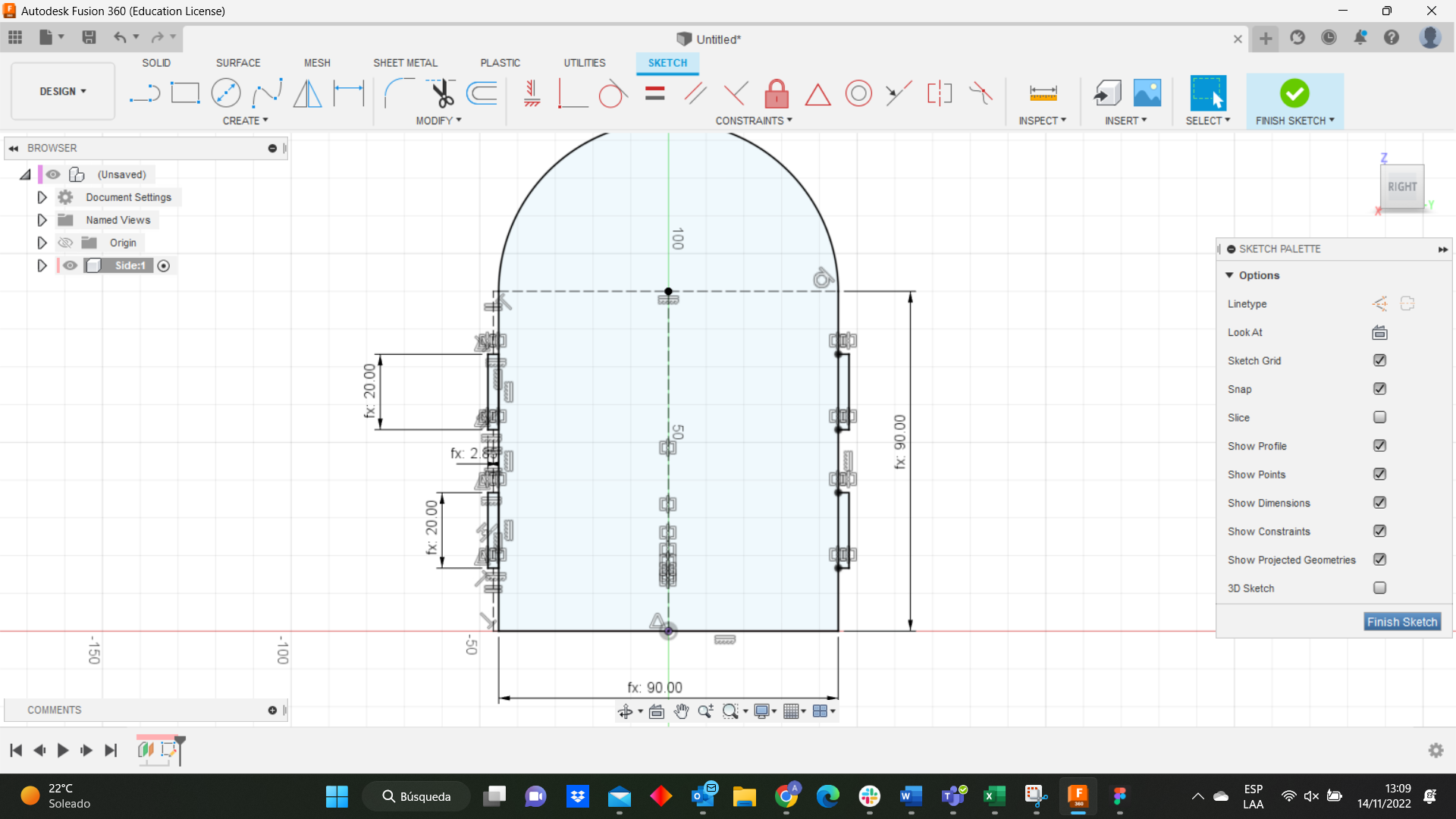
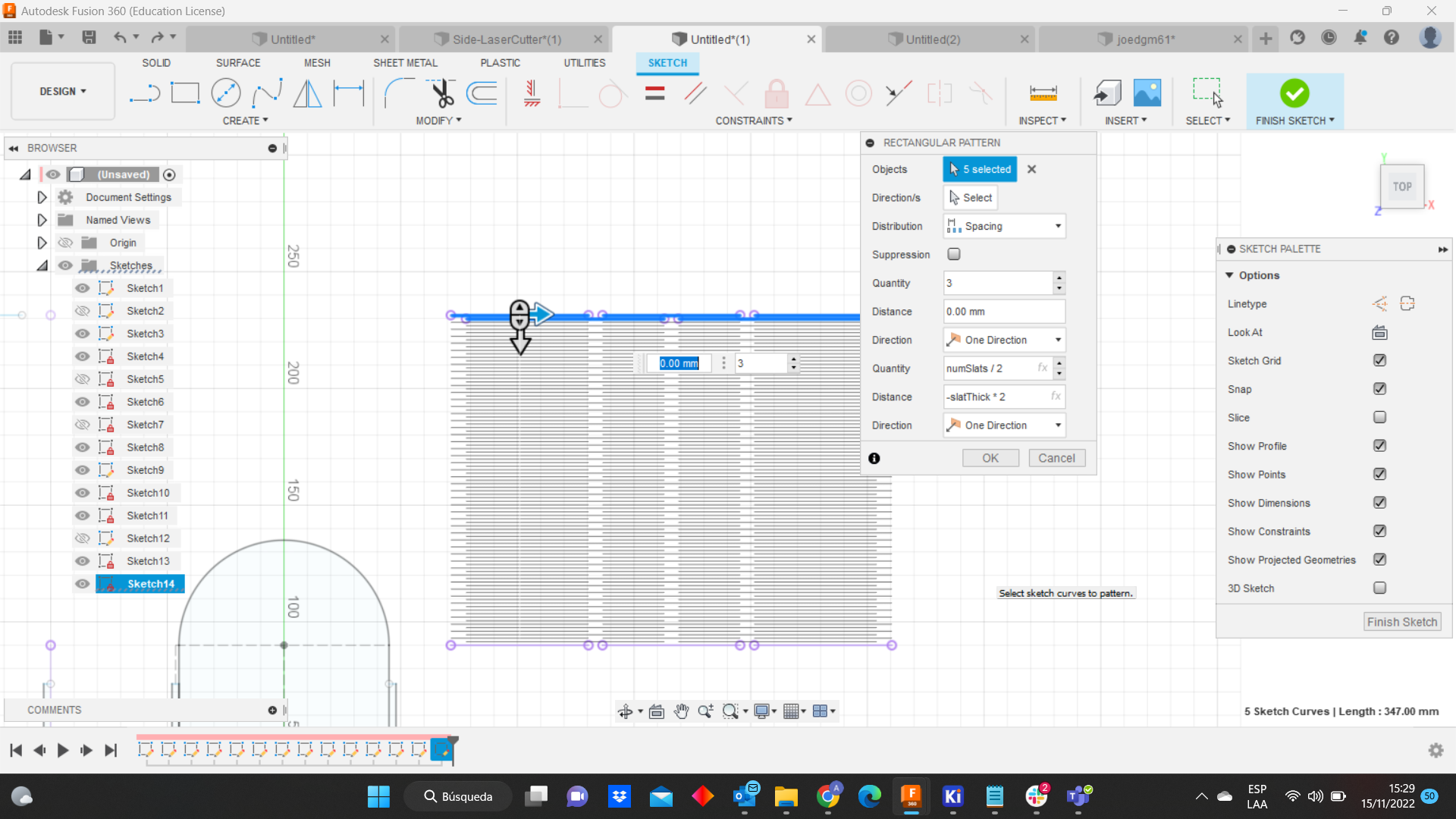
I did not care about the other side because I am going to create it in the Rhino software next to the laser cutter. Now, I need to create the arch and the sides and I sketched it in 3 parts. First, I did a rectangle and I cutted the sides which are the finger-joints. The arch where I sketched the living higes. At the same plane at the top of the arc, I created 3 lines with a gap by 6mm and under them I sketched 2 lines more with the same gap. Then, The measure of the dimension from the sidearch is 141.372mm, I have got this value using the formula: 2piR*Angle/360 -----> r=45mm; angle=180° Value=141.372mm. So, I started to draw the 3 lines at the top of the rectangle and the 2 more lines under them. I used the mirror command ony for the first group of lines. To create all the living hinges I used the rectangular pattern, I selected the 5 lines and wrote the quantity and the distance, as you can see the following pictures:
After that, we got the living hinges.
Finally, I drew the last rectangle cutting the finger-joints.
Afterwards, I exported the design in .DXF format to open it in the rhino software.
Laser cutter
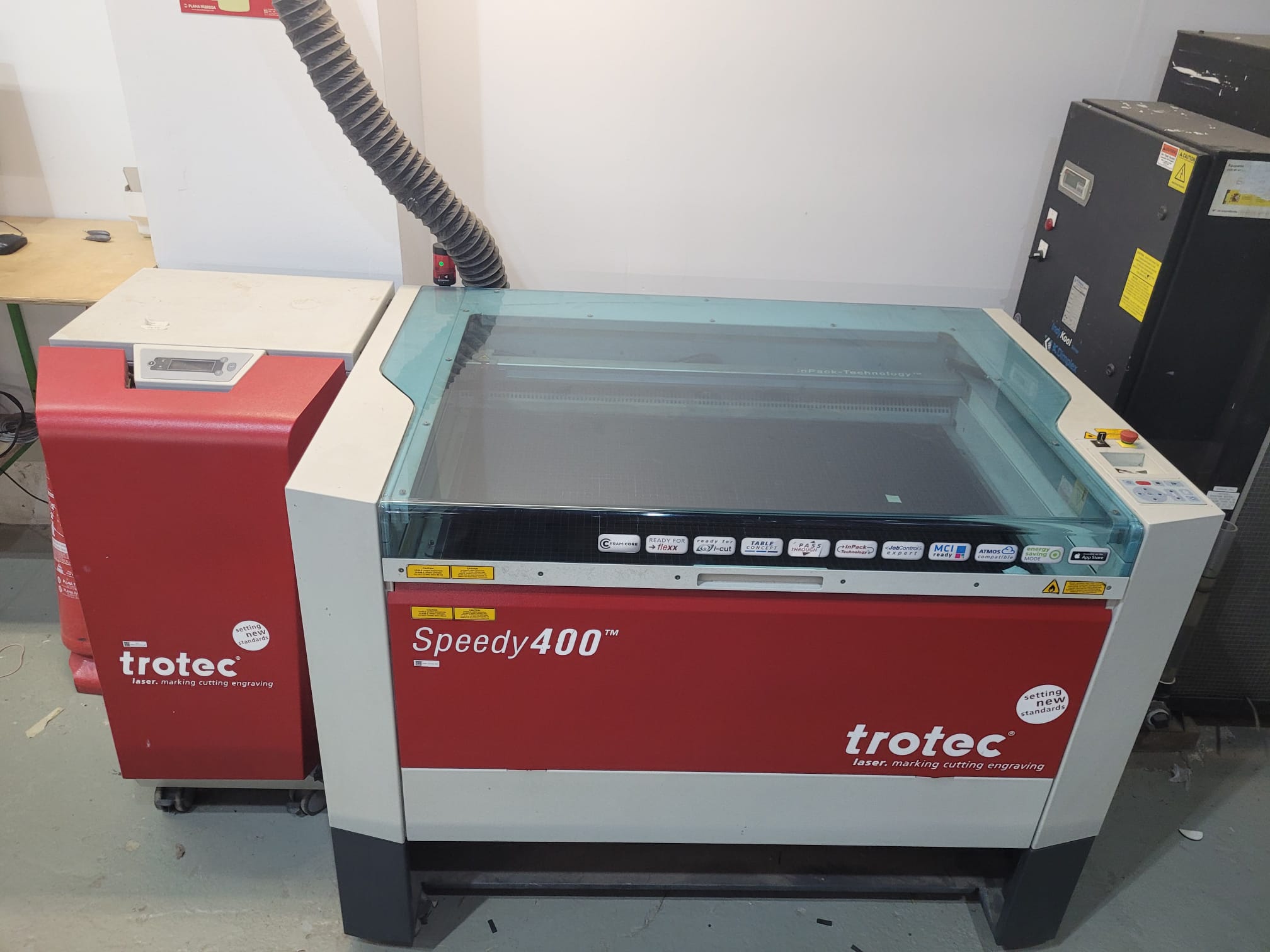
Here in the fab we have the Trotec Speedy400. It is a 1000x610mm 100W machine. This one was used in the group assignment. The trotec uses rhino and its own interface to send the file to cut. The software is basically used for importing files and assigning colors and layers.
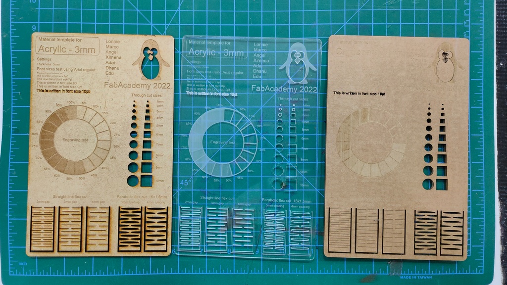
It is important to mention that we did some tests with a standard template for 3 different materials. These were the settings:
-
Acrylic
-
Cutting: 95 Power, 0.5 Speed, 20,000 PPI
- Engraving: 70 Power, 100 Speed, 20,000 PPI
- Raster (low): 40 Power, 100 Speed, 1,000 PPI
- Raster (med): 60 Power, 100 Speed, 1,000 PPI
-
Raster (high): 80 Power, 100 Speed, 1,000 PPI
-
Cardboard
-
Cutting: 40 Power, 1 Speed, 1000 PPI
- Engraving: 40 Power, 2 Speed, 1000 PPI
- Raster (low): 70 Power, 80 Speed, 1,000 PPI
- Raster (med): 80 Power, 80 Speed, 1,000 PPI
-
Raster (high): 90 Power, 80 Speed, 1,000 PPI
-
MDF
-
Cutting: 55 Power, 0.5 Speed, 1,000 PPI
- Engraving: 40 Power, 2 Speed, 1,000 PPI
- Raster (low): 70 Power, 80 Speed, 1,000 PPI
- Raster (med): 80 Power, 80 Speed, 1,000 PPI
- Raster (high): 90 Power, 80 Speed, 1,000 PPI
We have a datasheet on the right of the laser cutter. That will be used to cut our design. Here we have a picture of the result of the 3 materials.
Laser cutter Workflow
- Turning on the machine.
-
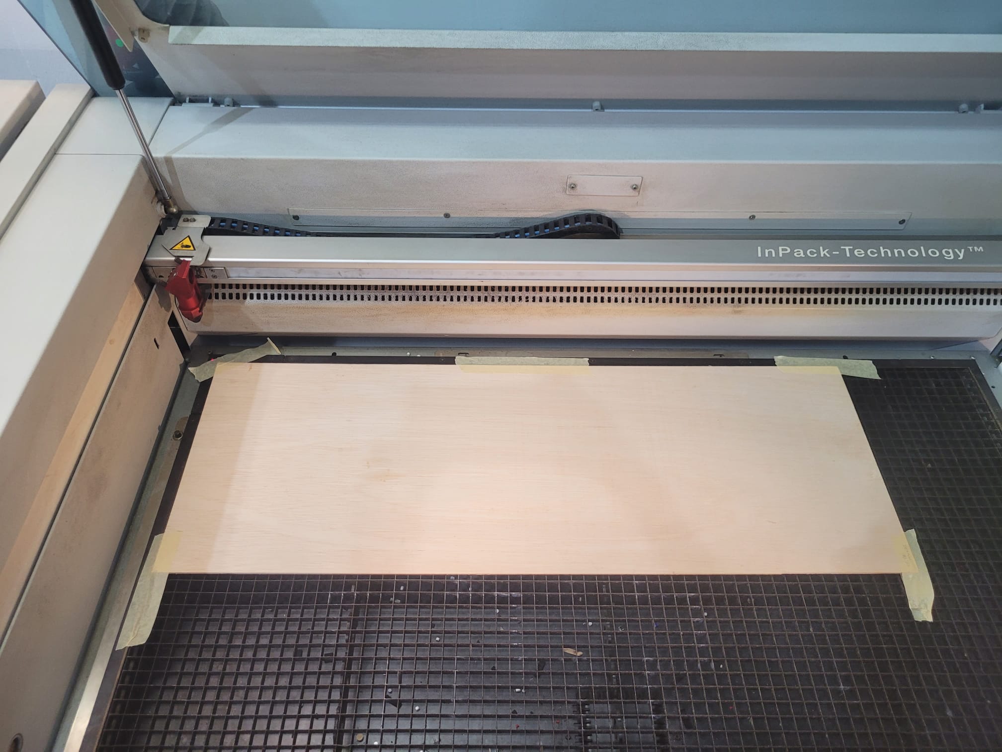
Loading the material.
-
Setting focus and starting position for the laser.
- Turning on the air extraction.
- Exporting the file, it has to be a 2D Design, that can be read by Rhino, DXF recommended.
- Opening the file with Rhino on the computer connected to the cutter.
- Checking settings and dimensiones of the file to make sure that everything is fine. This a picture of the final design made it in rhino.
-
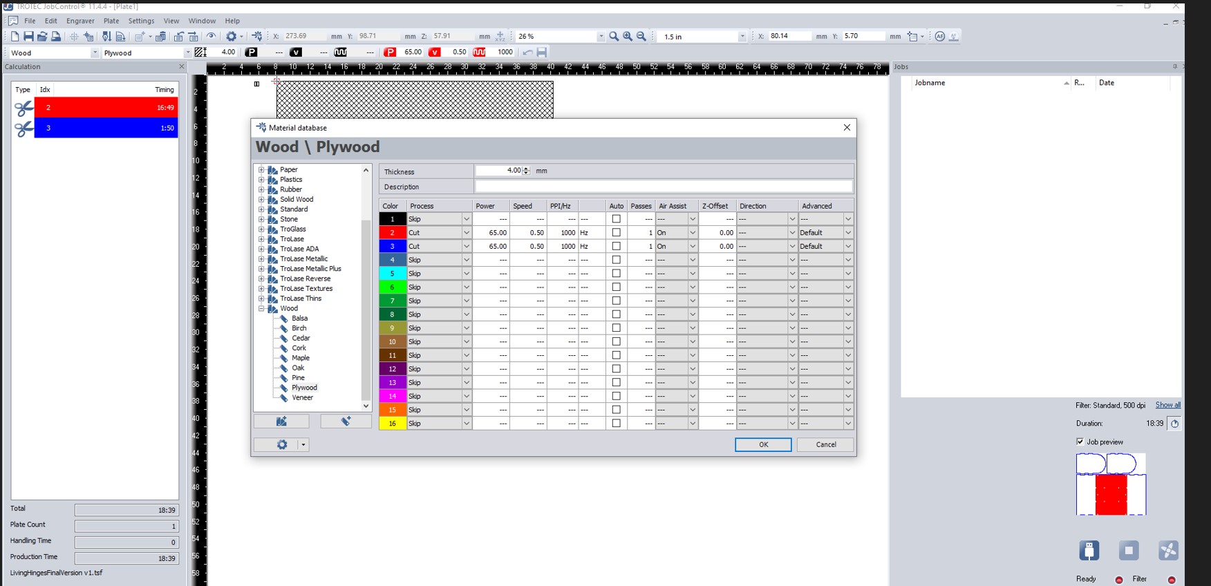
Setting up colors/layers to control cut order and group things that need the same laser settings. I used The reed and blue.
-
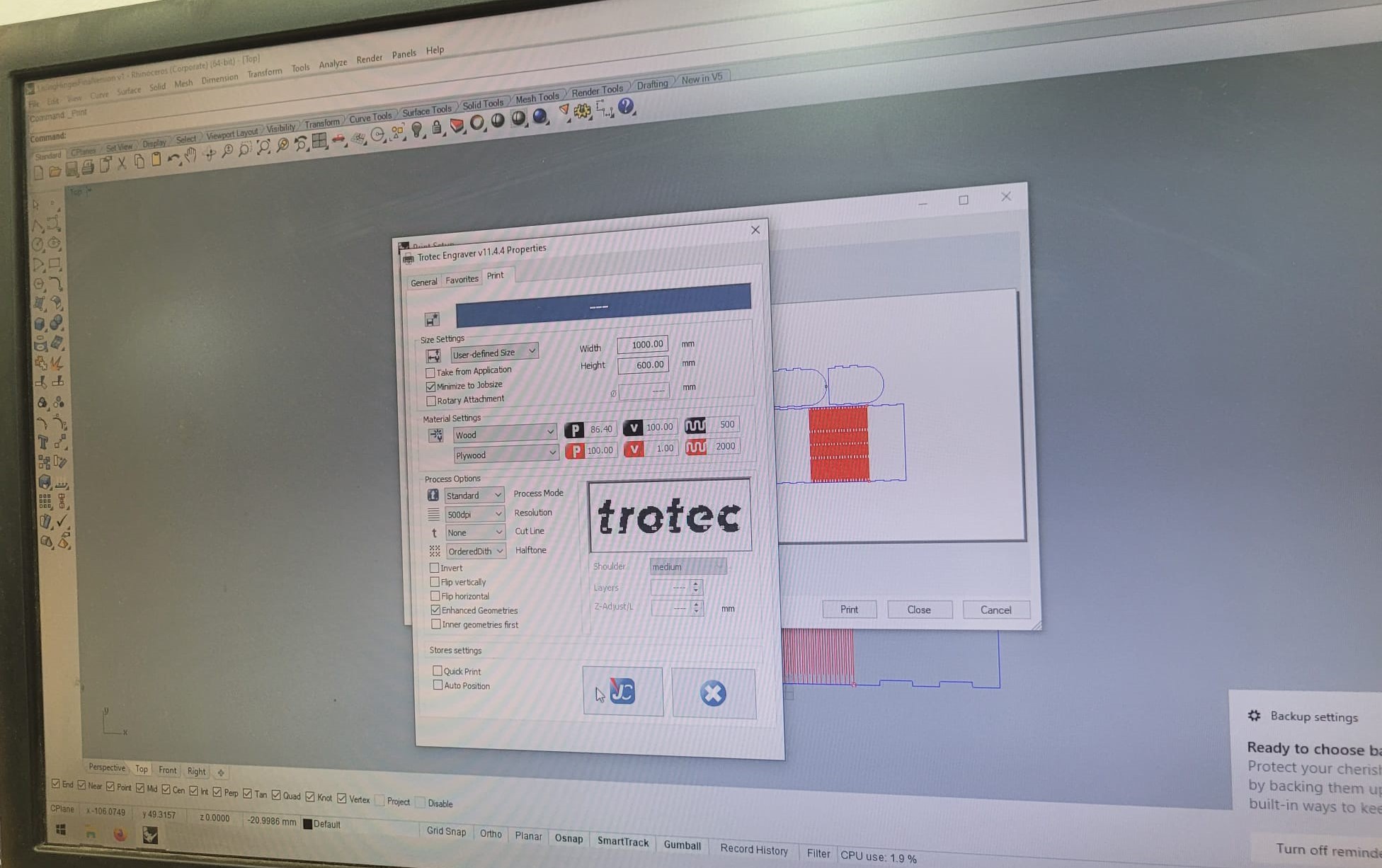
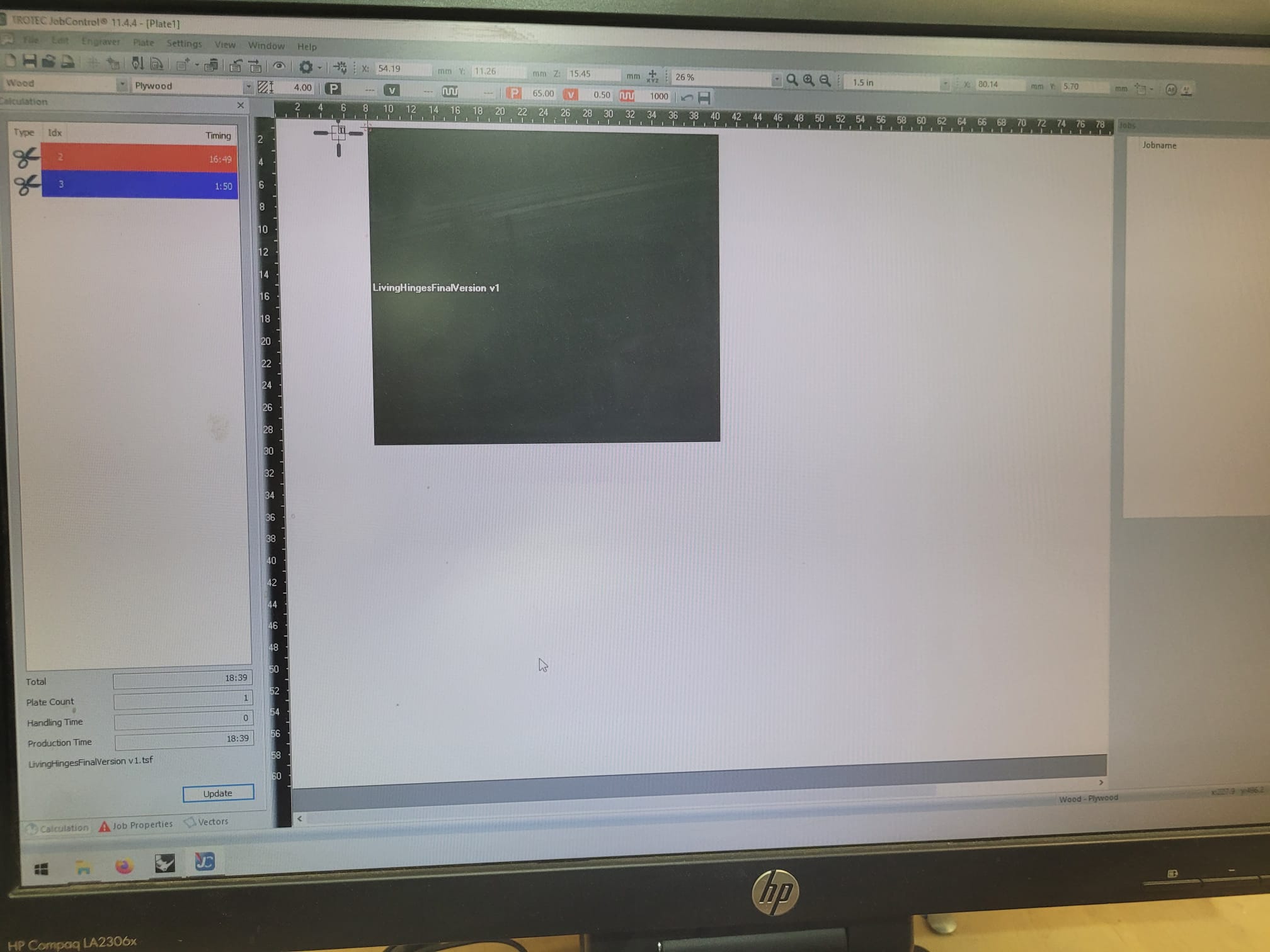
Doing file -> Print to the cutter job control software.
-
Looking at the file in the job control software to make sure the dimensions are ok. I recommend you to see the screen and the material on the machine.
-
Setting up the proper cut order using colors/layers. Another important thing here is to do a small test cut It’s good to do a small test cut to verify that the speed, power, and frequency settings are appropriate for the material you are using. Having done the test I had to change my settings for the values from the polywood of 4mm.
- Clicking on the run icon.
Here a process video:
LaserCutter from Angel Erazo on Vimeo.
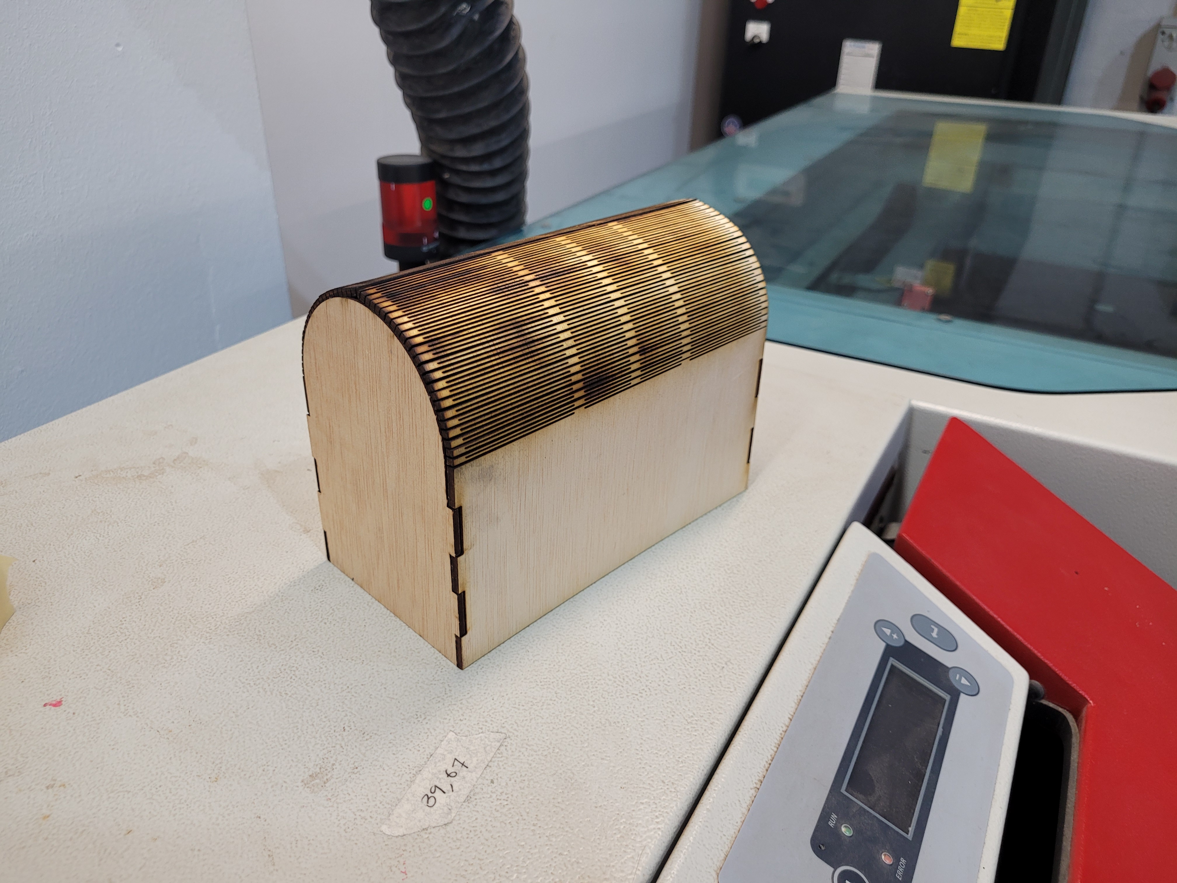
The final result is:
Vinyl cutter
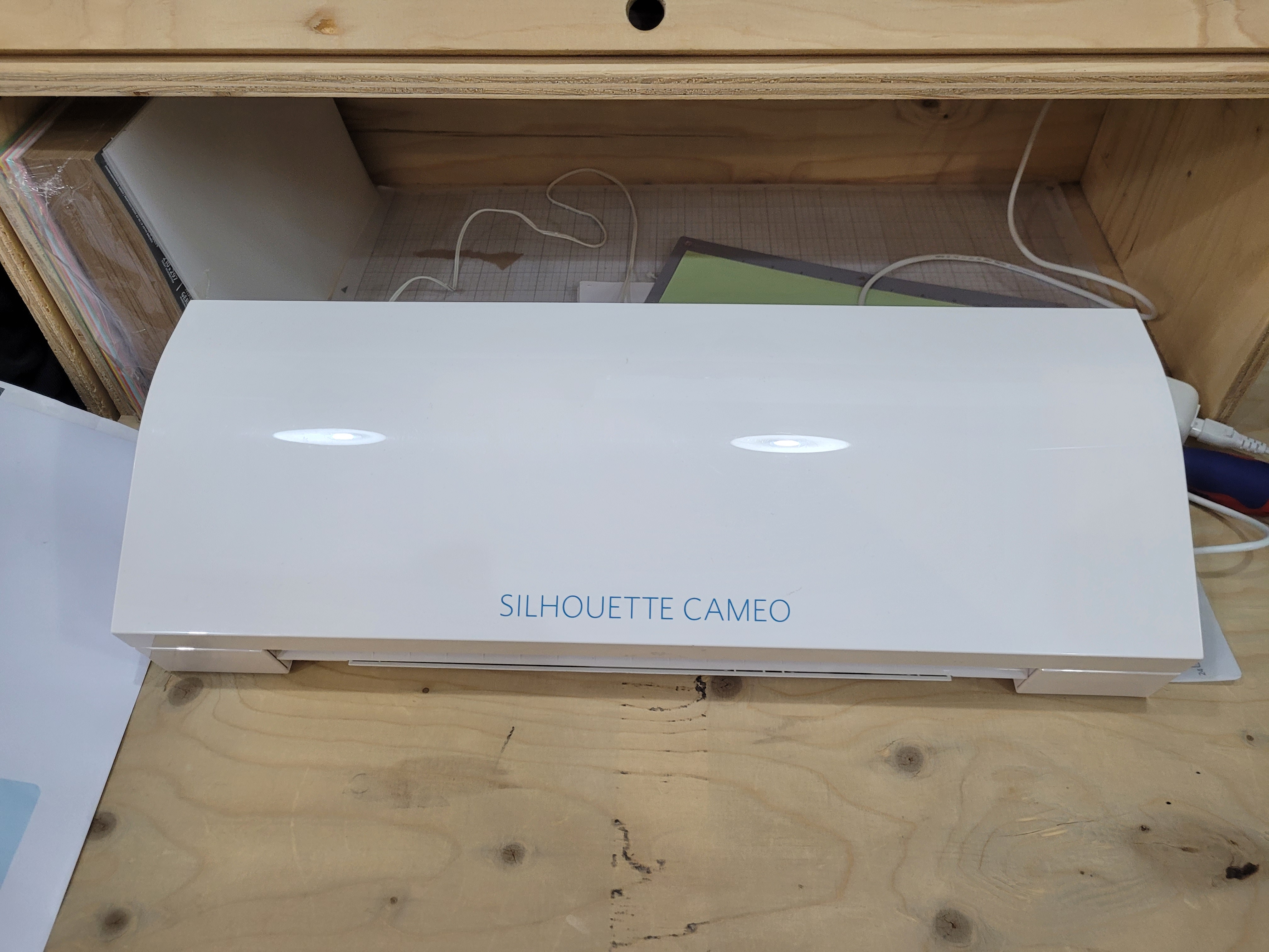
Here in the FabLab we have two vinyl cutters, the Roland CAMM-1 and the Silhouette Cameo 3. The Roland has more power than the Silhouette and it is better for bigger cuts and figures. On the contrary, the Silhouette is easier to use, with a more intuitive software, and offers a really good resolution for small cuts. For this reason I decided to work with the Silhouette as I need to do really small cuts for my design.
Sketching
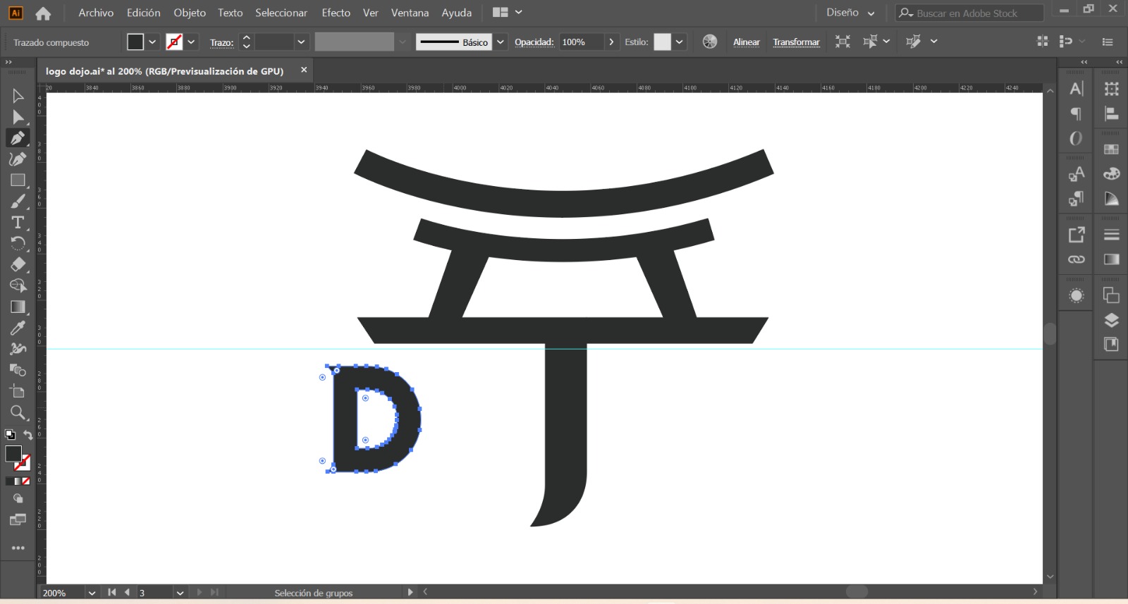
I had some ideas in mind for my drawing but I decided to do my own logo. I sketched a dojo in Adobe Illustrator and inkscape.
Vinyl Cutter Workflow
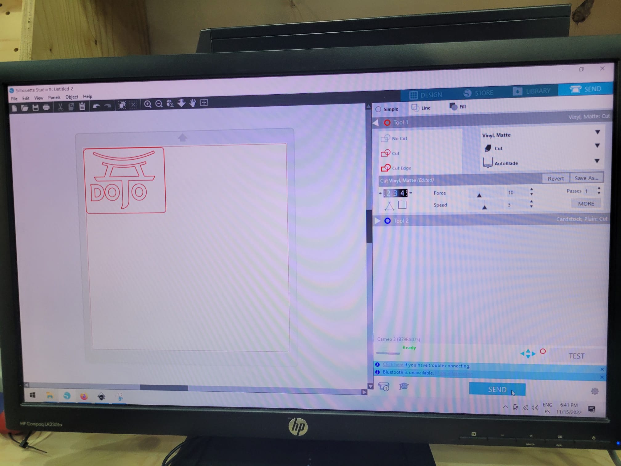
- Import .dxf file into Silhouette Studio software.
- Select material as Vynil Matte.
- The tool is set to Cut.
-
I had to experiment with the force and speed and go through a set of tests, eventually I set the force 10 , speed 5 ands passes 1.
-
Make sure the tip of the pen is not too soft as it might bend under pressure.
- The file should contain only vectors.
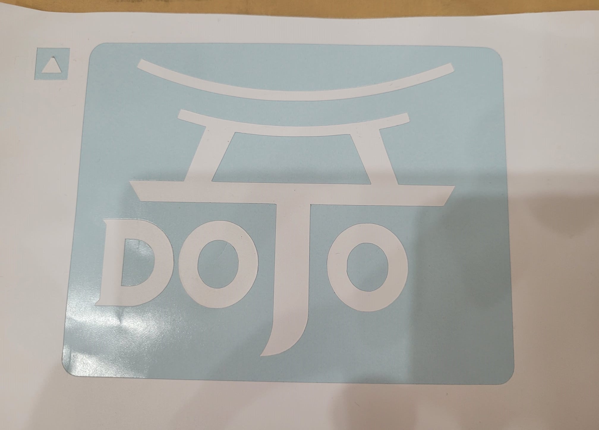
- Testing the setting If you can take the material off easily is ok and you can start. You can see a image of my testing.
- Set the origin by pressing the “Origin” button on the control panel.
There is a video of the process:
VinylCutter from Angel Erazo on Vimeo.
Then, I took the part of the square off, you have a picture of it:
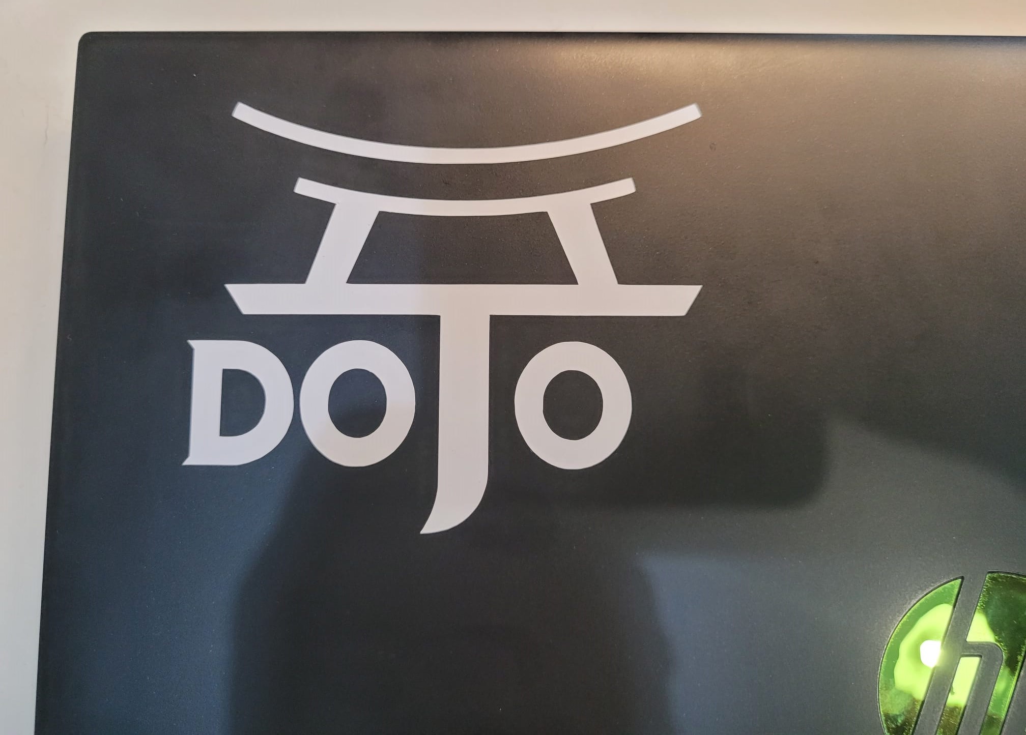
To transfer the sticker to my laptop I used a sticky tape to avoid damage.
![]()
The final result:
Group Assignment
Here is the link.