13. Input devices
For this week, I have to measure something adding a sensor to a microcontroller board that I have designed and read it. There are many sensors and it depends on what you want to do to choose one. In my case, I choosed to practice with a capacitive sensor.
A little of theory behind capacitive sensor
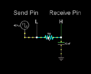
The principle of a capacitive sensor is detecting something conductive or that has a significantly different permitivity than air, like a human body or hand. So, in a resistor-capacitor circuit board is measured the time it takes to go form one state to the other. I find one example in this link. This a picture of a RC circuit:
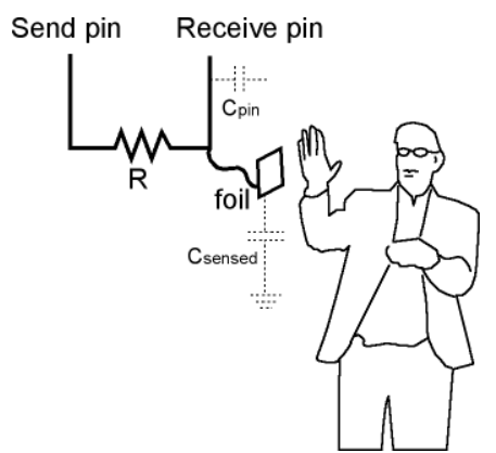
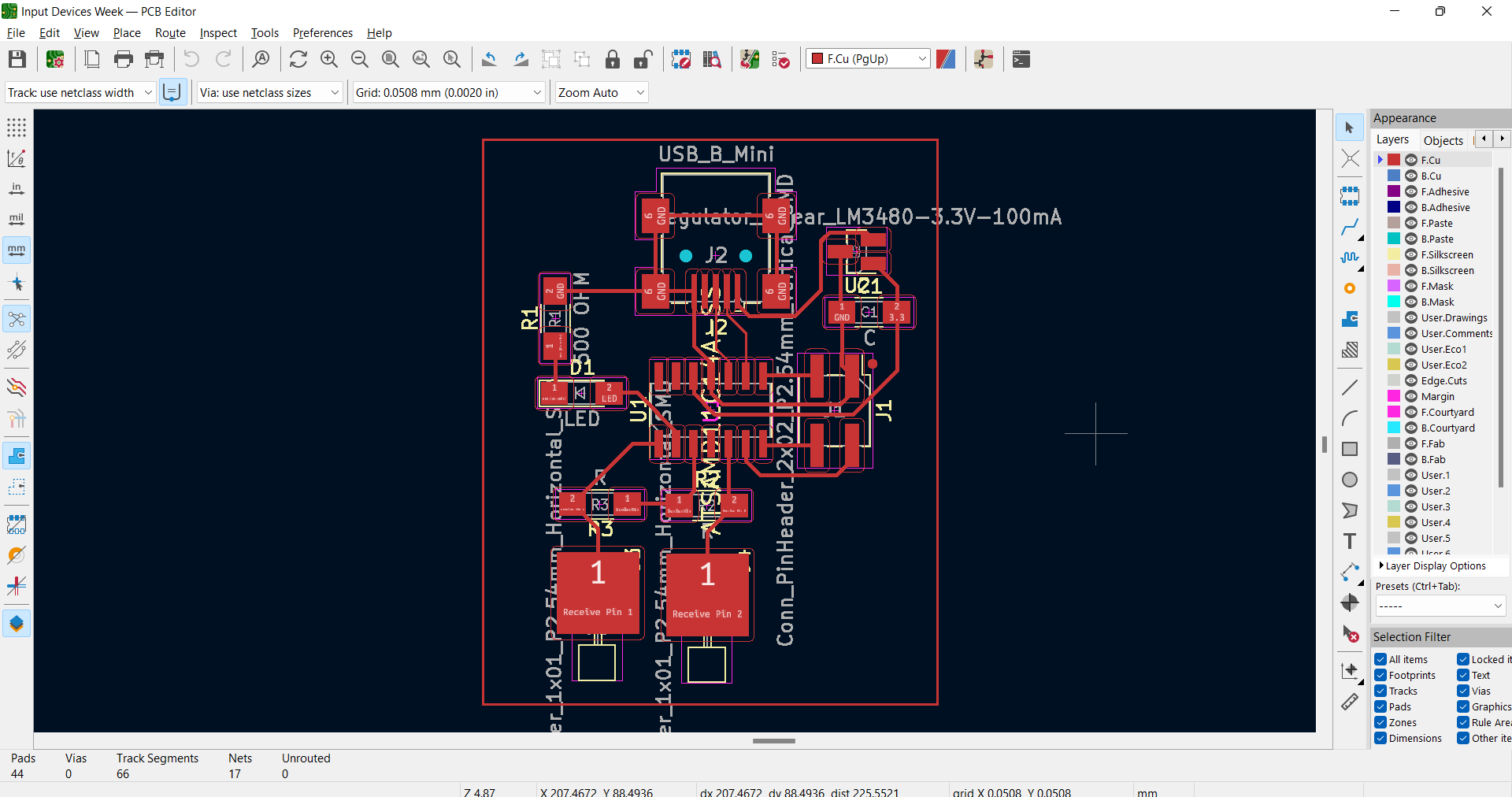
Now, we can take all this concepts to design a capacitive sensor. However, instead of using a capacitor, I am going to design a new board which can perceive the electrical capacitance of the human body. On the board, we need to choose a microcontroller send pin and receive pin because those will read the voltage when we touch the sensor. We can use as sensor material any metallic objects such as coin, aluminium foil, a copper piece, etc. Do not forget that the recieve pin must be connected to the sensor material, you can see it on the PCB Editor on Kicad.
By the way, I recommend you checking this documentation from the oficial arduino website here. It helped me a lot.
PCB Designing
Understanding how the capacitive sensor works, it was more easy to design the PCB. We must start with the schematic, this is a screenshot:
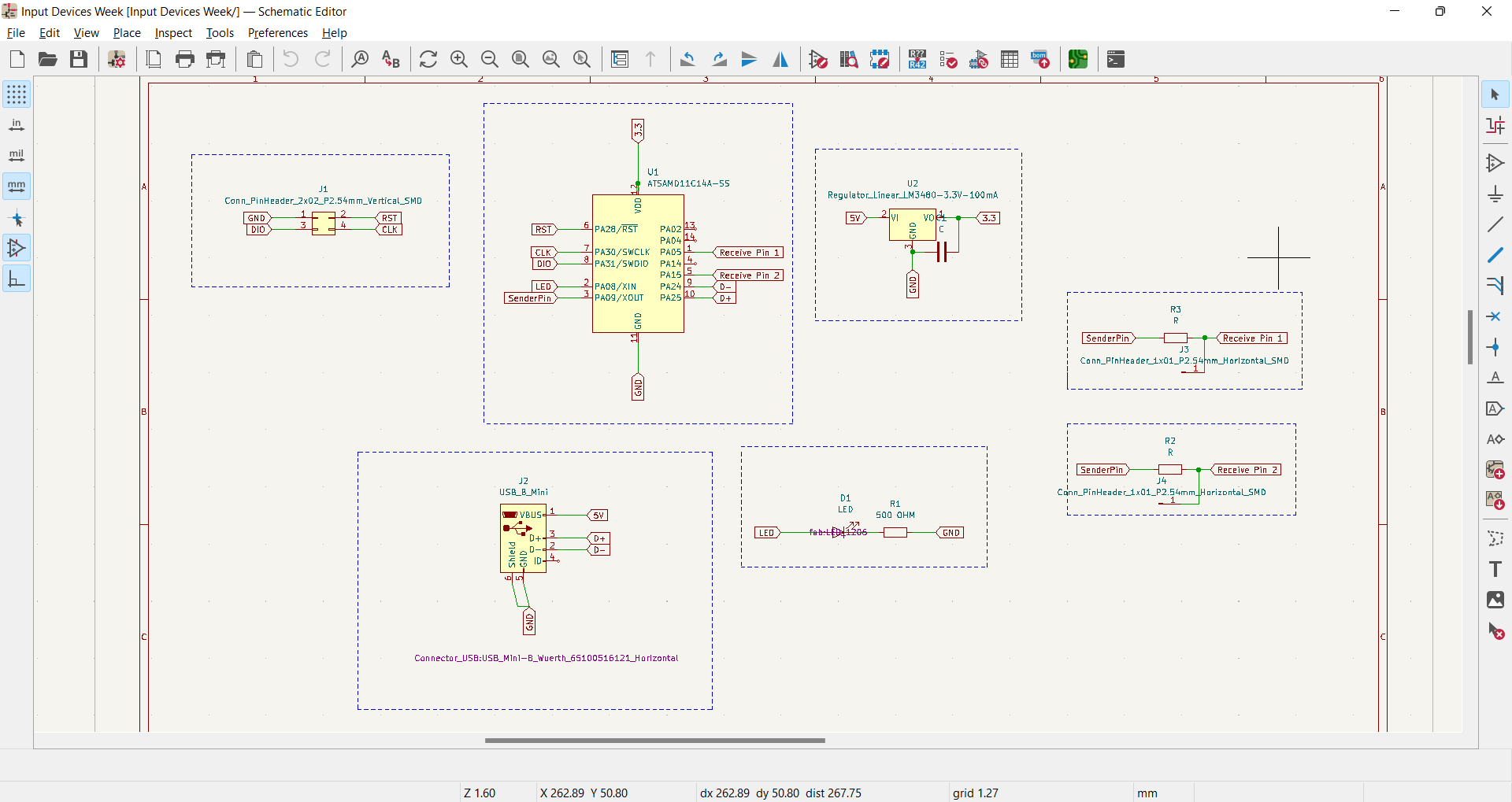 As you can see, I choosed to add 2 sensor on the board and it depends on each person to put the sensor outside or inside of it. Besides, many sensors can have only one send pin, but each must have its own receive pin. That is why, I have one “sender pin” for the two sensor. Another important thing is to add a 1M Ohm Resitor that allows us to regulate the voltage when we touch the copper square on the board.
Milling the board
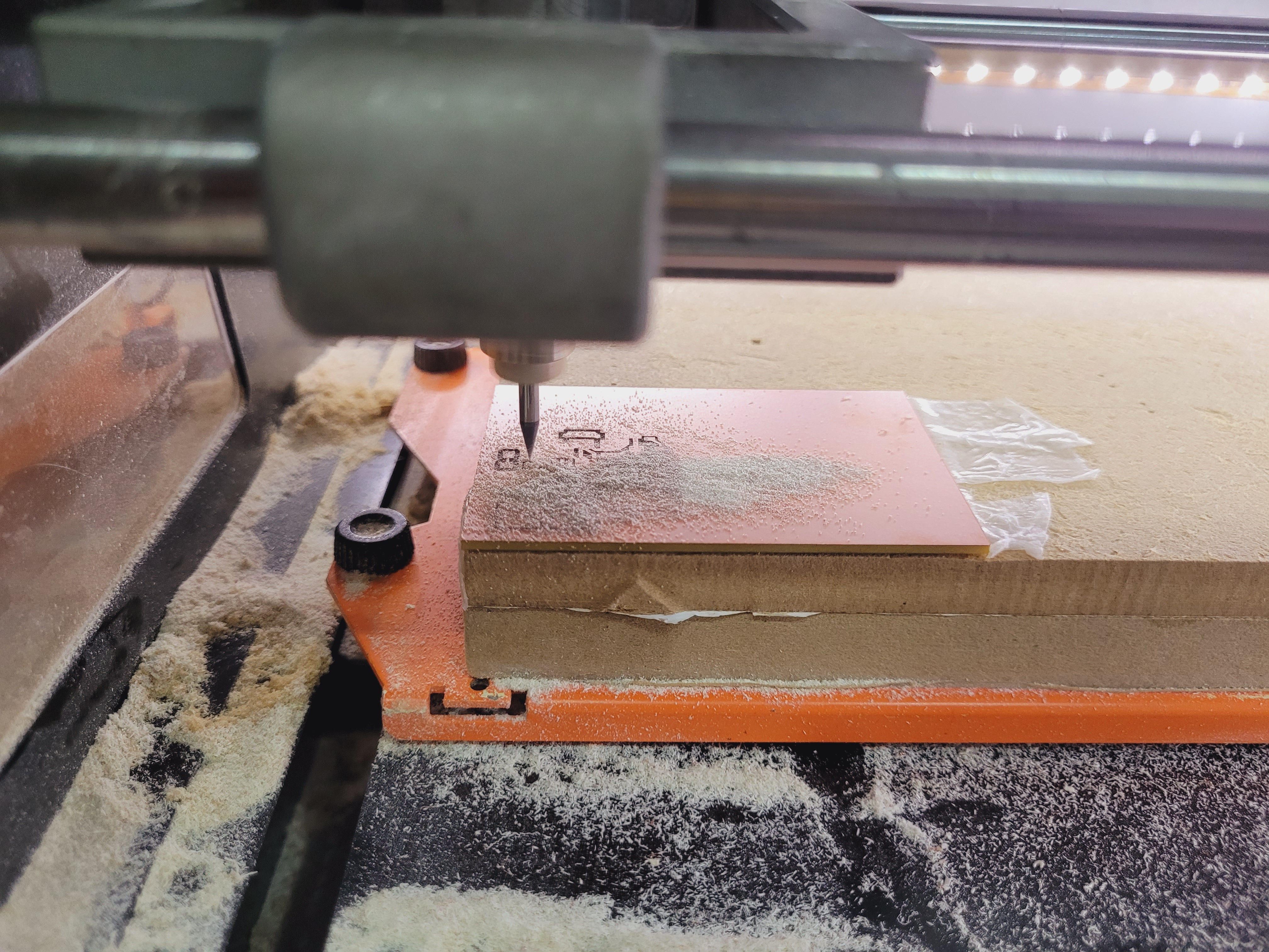
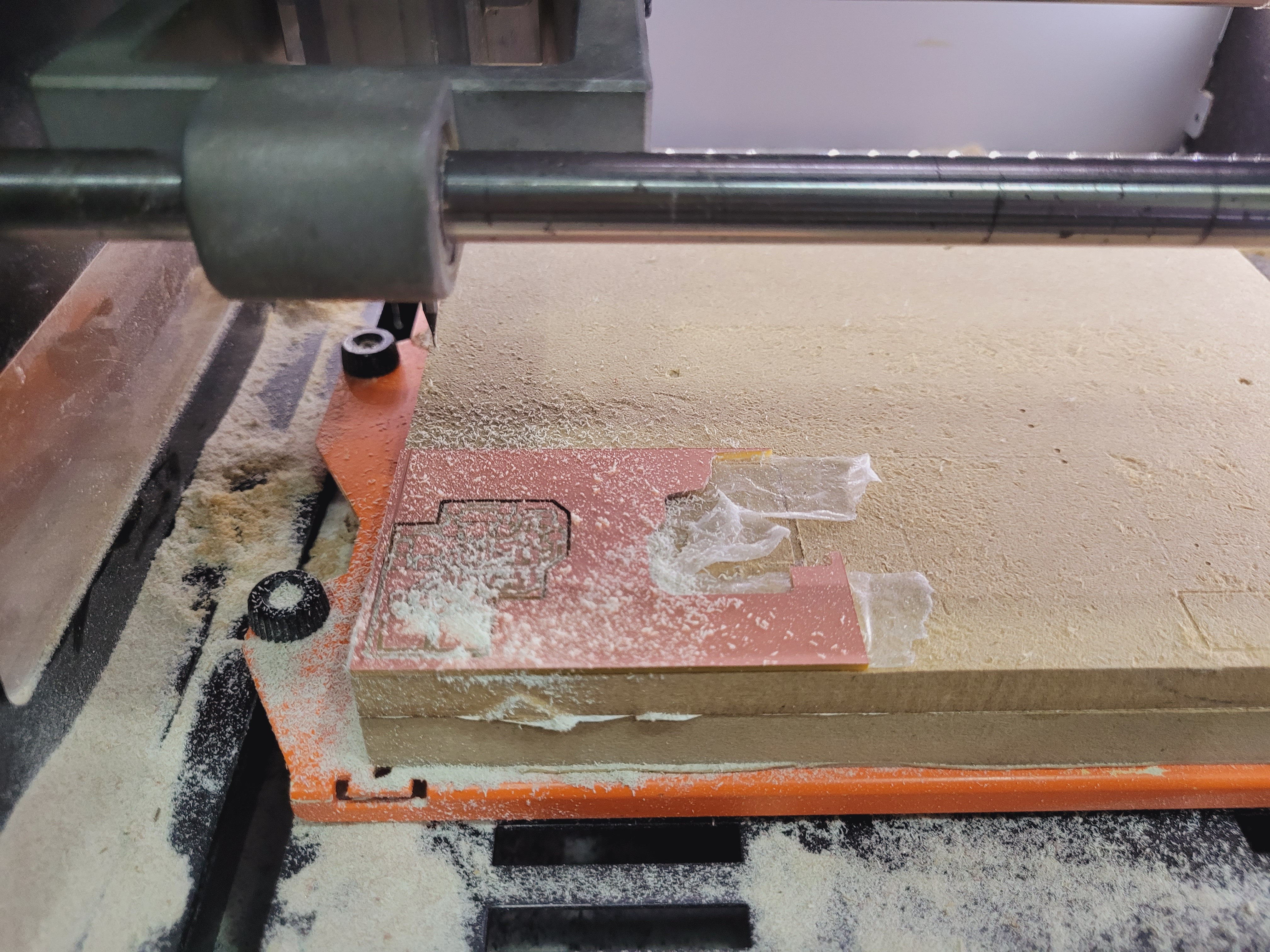
I have been follow the same workflow for milling. I have some pictures of my milling process:
Programming
Then, we have to flash this board with the programmer but here I had some problems because the new board was not recognized. Later, I realized that I made a big mistake I had not changed the pad size:
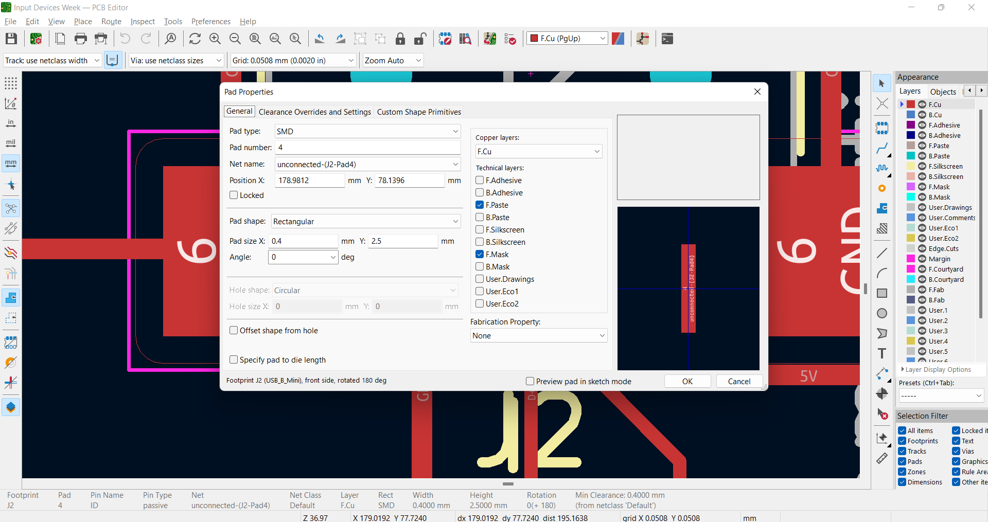
It took me many hours to figure out the solution but I will never forget to make this change because I had to repeat all the milling part again.
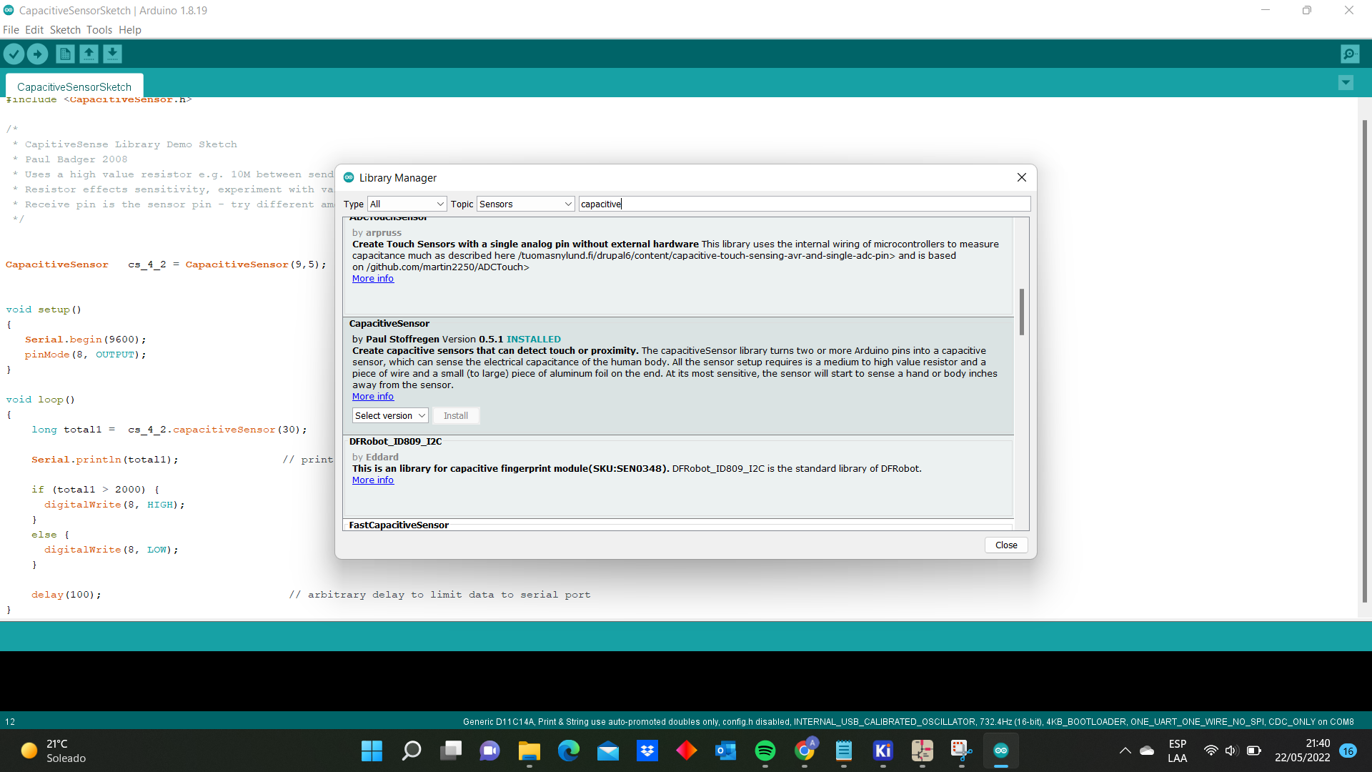
Once everything was soldered I made a program in Arduino IDE. The first step was to install the library in Arduino IDE:
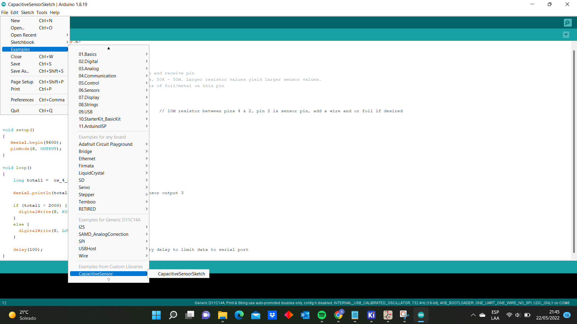
And then I opened the example given in the library:
#include <CapacitiveSensor.h>

CapacitiveSensor   cs_4_2 = CapacitiveSensor(9,5);        // 10M resistor between pins 4 & 2, pin 2 is sensor pin, add a wire and or foil if desired
void setup()
{
   Serial.begin(9600);
   pinMode(8, OUTPUT);
}

void loop()
{
    long total1 =  cs_4_2.capacitiveSensor(30);

    Serial.println(total1);                // print sensor output 3

    if (total1 > 2000) {
      digitalWrite(8, HIGH);
    }
    else {
      digitalWrite(8, LOW);
    }

    delay(100);                             // arbitrary delay to limit data to serial port
}
This is the final result:
Input Devices from Angel Erazo on Vimeo.
Group Assignment
Here is the link