08. Computer controlled machining
Group assignment:
-
Complete your lab’s safety training.
-
Test runout, alignment, spe-eds, feeds, and toolpaths for your machine.
-
Document your work to the group work page and reflect on your individual page what you learned.
Individual assignment:
- Make (design+mill+assemble) something big .
extra credit: don’t use fasteners or glue. extra credit: include curved surfaces.
1. GROUP ASSIGNMENT:
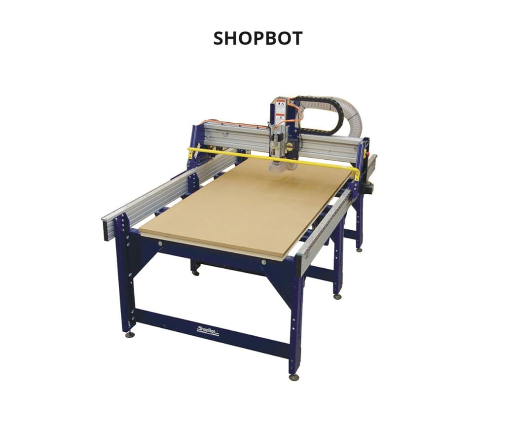
In the Fab lab Esan, we have the following CNC milling machine:
SHOPBOT PRSalpha 96-60
The PRSalpha 96-60 is a 3-axis CNC for working with full plates of various types of materials, mainly wood and engineering plastics. It is not suitable for metal working.
It has a chip suction system and a removable fourth shaft.
You can obtain more information in the following links:
FEATURES
-
CATEGORY: CNC Routers
-
FRAME CONSTRUCTION: Gantry
-
NUMBER OF AXES: 3-axis
-
X - AXIS TRAVEL: 2591mm
-
Y - AXIS TRAVEL: 1575mm
-
Z - AXIS TRAVEL: 203mm
-
RESOLUTION: 0.0102mm
-
MAXIMUM SPEED: 152 to 635 mm/sec
-
SOFTWARE: VCARVE
SAFETY TRAINING
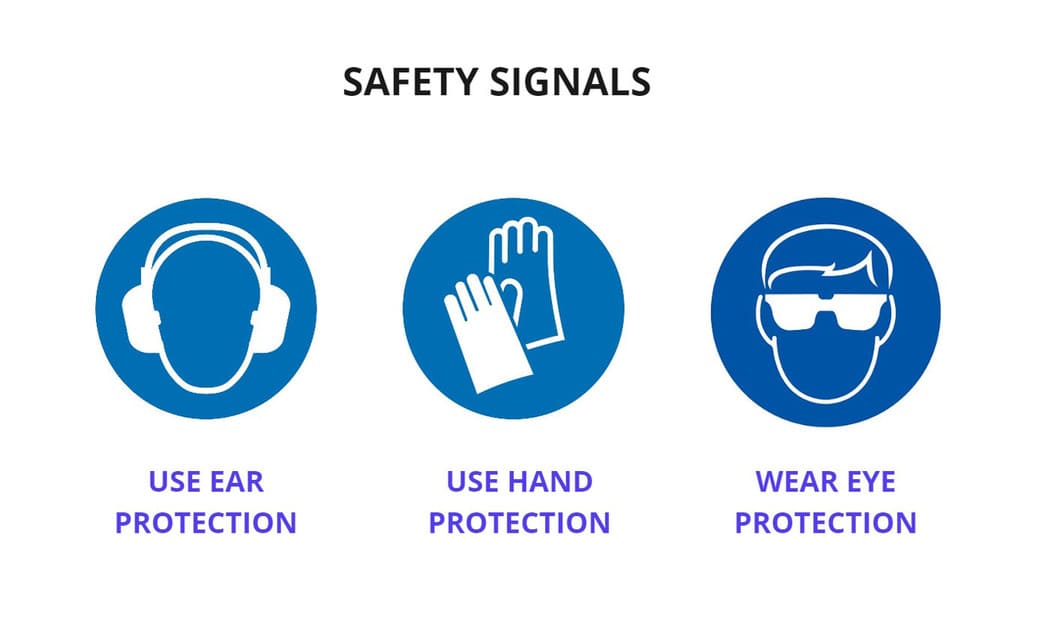
Something we learned in class is that we must be very careful with this type of machine, because if we do not take the necessary safety measures, it can be deadly. Because of this, we are going to explain the necessary procedures and safety equipment, so that we can protect ourselves and the work can be done properly.
-
SAFETY EARS: Is a noise insulator to prevent damage to the inner ear, as the machine generates too much noise when working.
-
SAFETY GLASSES: Prevents residual material from reaching our sight. Flying sawdust, material chips, and other debris can cause serious eye injury.
-
SAFETY GLOVES: Prevents chipping of hands.
-
GRAPHIC SIGNS: There is a yellow line on the floor that outlines the machine, this indicates the limit that we must not exceed when the machine is running, to avoid possible accidents with the moving parts of the machine.
-
YELLOW BAR: This is a yellow bar that allows you to move the machine head without having to touch the moving part of the machine. Never place your hands on the rails of the ShopBot. Be aware that the machine may move unexpectedly in any direction, which can cause serious injury if your hands are in the path of movement.
-
NOISE INSULATION: The machine causes a noise of 87 decibels, this noise level is harmful in prolonged exposure. It should be in isolated rooms in the laboratory in order to isolate the noise as it is harmful to the operator.
-
EMERGENCY BUTTON: The machine has emergency buttons in case of jamming and you must know the location of each one.
-
WRENCH FOR NUT AND IGNITION KEY: The machine only works if the ignition key is in place and the wrench is used to change the end mill. They are connected by a short cord, if you want to change the end mill, you will have to disconnect the key (because the cord is not so long), so you will avoid accidents because there is no way to turn on the machine without the ignition key.
-
CLOTHING AND ACCESORIES: Do not wear loose or baggy clothing because it may get caught in the machine. Short sleeves are recommended. Do not wear jewelry, such as necklaces or rings. It is preferable to wear your hair short or if it is long it should not be loose but tied up.
HOW IT WORKS
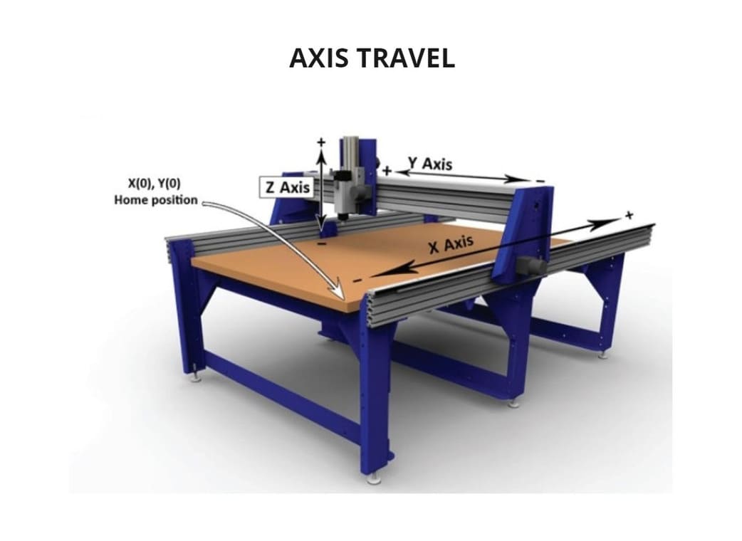
There are some things that we have to be very clear about and that is the starting point where the cutting begins. Remember that there must be a sacrificial bed underneath, to avoid damage to the end mill.
I show you how the axes work and what is the starting point in the following image:
TEST RUNOUT, ALIGNMENT, SPEEDS, FEEDS, AND TOOLPATHS
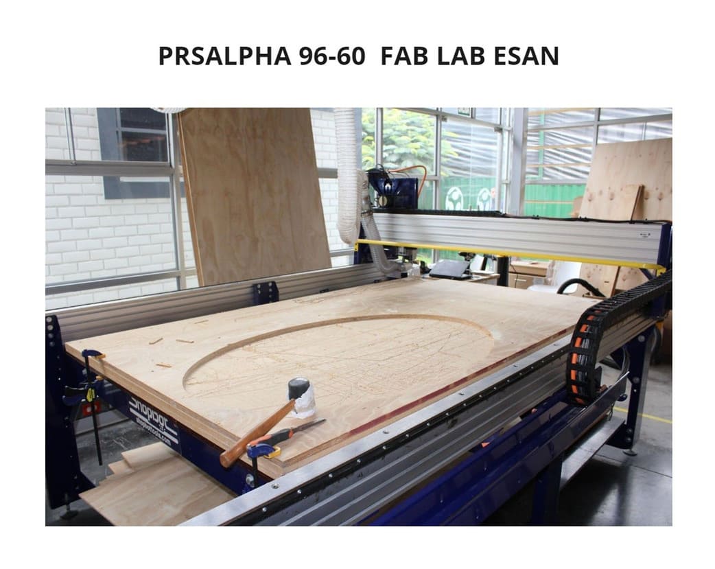
It’s time to test, for that I first designed the parts I was going to cut and then I used the Vcarve Software to configure the cuts, both speed, trajectory and other parameters.
You can see the PRSAlpha 96-60 we have in the Fab Lab ESAN below:
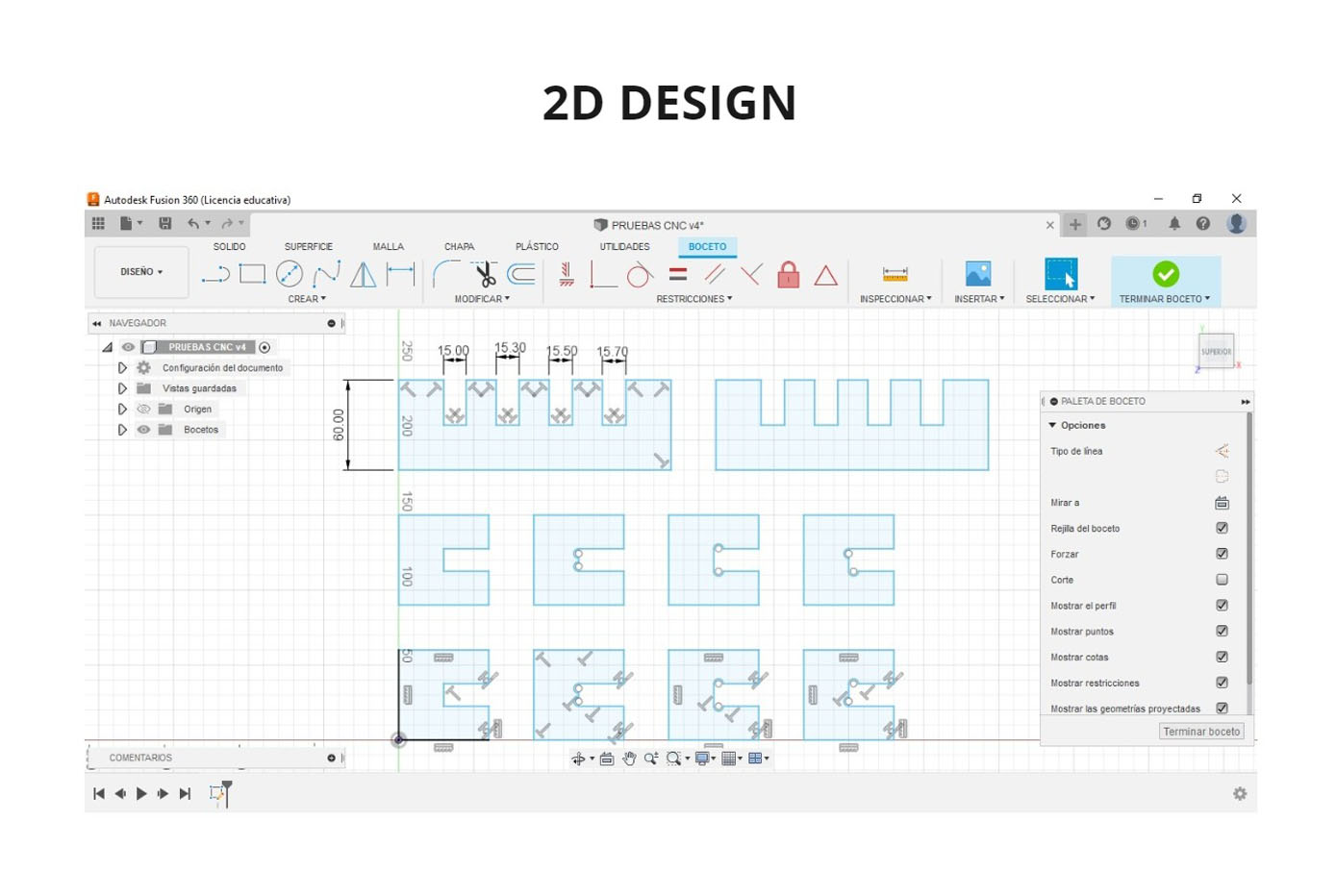
I made the design in Fusion 360, first I made 2D traces and then a 3D test.
-
The MDF board has a thickness of 15mm according to its data sheet, but in real life it varies by a few millimeters, not all the boards will have the same size. That is why it is important to make tests.
-
I made two comb-shaped pieces, with openings that vary in ascending size: 15mm, 15.30mm, 15.50mm and 15.70mm. I will cut these pieces to test the sockets.
-
Additionally I made small pieces with different endings, this is because the milling machine must make an additional run because otherwise the corners will not be visible and the pieces will not fit completely.
-
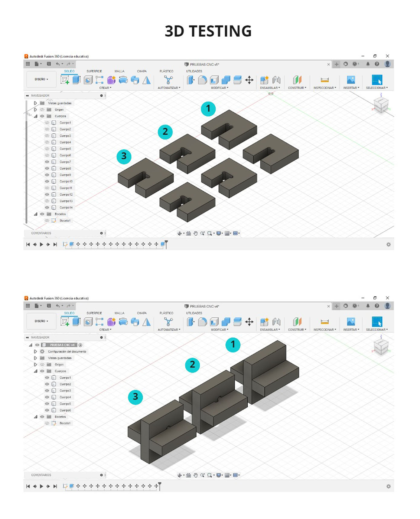
I made small terminations in the inside corners so that the end mill makes the path and lifts them in 3D. I divided them into MODEL 1, MODEL 2 and MODEL 3.
-
MODEL 1 : No visible holes when assembling. The problem is that if the end mill makes a few millimeters more of its path, the pieces would be fitting further inside, exceeding the limits that we had set.
-
MODEL 2 : Visible holes, you can see small semicircles in the corners of the socket, but it is the safest as there will be no problems when joining the pieces.
-
MODEL 3 Visible holes but also some hidden ones, I found it interesting and I will use this one for testing the lace.
SETTINGS
In order to cut the pieces, we need to use the VCARVE software and follow the steps:
-
When you open the program, first click on:
CREATE A NEW FILE. -
Then you configure the
JOB SETUP, this depends a lot on the type of machine you have, you indicate the size of the work table and the starting point. -
More options will appear to create, edit and transform objects, you can also create vectors, add text, etc.
-
I exported the design I had made in FUSION 360 to .DXF and opened it in VCARVE.
-
My design was missing the additional path that I made in the 3D testing, but no problem, the program has the
CREATE FILLETSoption and with that you can add it. You can find different kind of fillts, I used theT-BONE FILLETSto all the internal corners. -
For
T-BONESI choose aTOOL RADIUSof 3.2mm. This depends on the size of the end mill you are using, my end mill is 1/4’‘, that means it is 6.34mm(almost 6.4mm), so the radius of theT-BONEhas to be 3.2mm to make a good stroke. -
Now, it is time to set the
TOOLPATHSthat is on the right side of the window. There you configure the necessary settings such as the type of end mill to be used, the speed, the number of passes, etc. -
Our traces are only in 2D, so we are going to work with the following option, click on
PROFILE TOOLPATH, a new window will appear called2D PROFILE TOOLPATH. -
My material has a thickness of 15mm, so I chose the option:
CUT DEPTH:15.5mm. WHY? It is recommended to have an additional depth of 0.5mm or 1mm because this will help the part to be cut completely. In case you set it to the exact value, there may be parts that do not come out well and you will have to use additional tools to make the cut. -
Next, I clicked on
TOOL>WOODand I choose:1/4 DOWN-CUT(57-910). I chose this option because it is the most used for straight cuts, it is 1/4’‘ in diameter and the type is DOWN-CUT because the chips go downwards, leaving less waste.
The recommended values for FEEDS AND SPEEDS are:
-
Spindle feed: 12000 RPM
-
Feed rate: 3.0
-
Plunge Rate: 1.0
If you change these values, be careful not to exceed the parameters too much because the end mill may break or heat up and cause a fire. For example, I changed from 1400 RPM to 1200 RPM, this is an acceptable value and allows to have a continuous and stable work.
Consult with your instructor before changing the parameters.
- I set the
PASSESto3.
HOW TO KNOW HOW MANY PASSES?
The number of passes varies depending on the thickness of your material, there is a tip that can help you to know the number of passes: the end mill can go down the same size of its diameter in each pass. This means that if I have a 1/4’‘ (6.35mm) diameter end mill, It can go down a maximum of that amount in each pass.
For example, if I have an 18mm thick material, a 15mm thick material and I am using a 1/4’‘ end mill, for both of them it will be 3 passes, but the CNC will calculate the depth of each pass in each case. But if I have a 12mm thick material, only 2 passes will be necessary.
-
In the
MACHINE VECTORSsection I choseOUTSIDE/RIGTH, because my cut for this piece is external and in this way the size of the piece does not vary. -
I also used the
ADD TABS TO TOOLPATHoption. This helps to prevent the workpiece from moving or slipping out of place during the milling cutting process, you will only need to make a small effort to remove the workpiece when the machine has finished working.
It is not necessary for all parts to have TABS, for very small parts it is not necessary. The amount of TABS will depend on the size of the design, you can add them automatically or manually, the program gives you those options.
-
After you have made all the settings, you must give it a name and click on
CALCULATE. I named mine as externo_prueba. -
You can visualize all the strokes with two options:
PREVIEW TOOLPATHSorTOOLPATHS SUMMARY, with the second option you can see how long the machine will take to cut your design, remember that theSCALE FACTORmust have a value of1.3to see the real time of each cut. My test pieces only took 00:01:23min.
IMPORTANT: After configuring, you must save the file, go to FILE > SAVE AS and save it in the folder of your choice, it will be saved in .CRV format.
Finally it is time to save each TOOLPATH, in my case I only have one type, so I went to the TOOLPATH LIST section, select toolpath that I had named as external_test , then I clicked on SAVE TOOLPATH (it is an icon that has the shape of a floppy disk).
Then, choose the option POST PROCESSOR: Shopbot TC (MM)(*.sbp) , because .sbp is the format supported by the shopbot and (MM) is because I set the file in millimeters so it should be saved in that format as well.
You can see more detail in the following pictures:

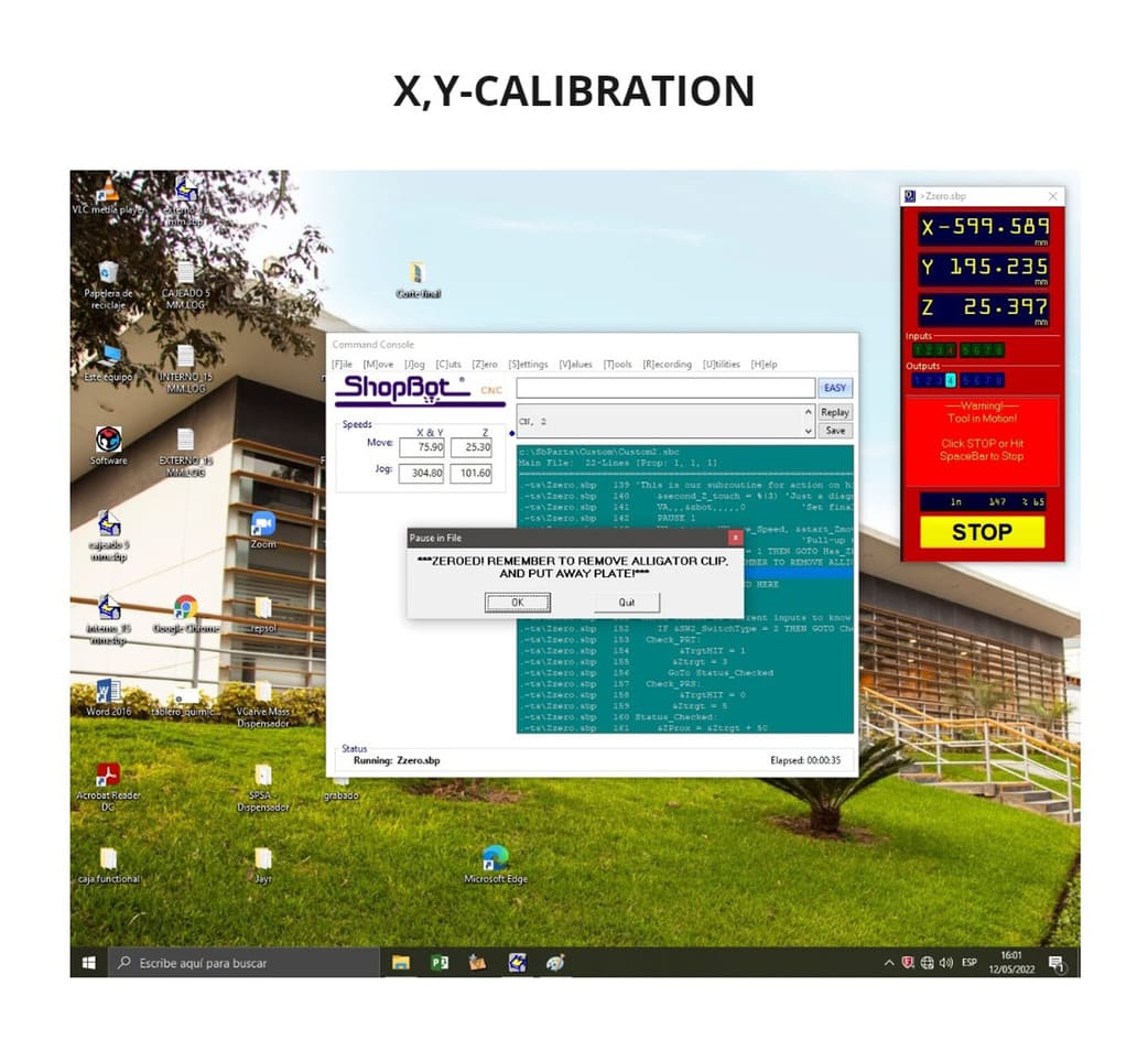
After you have the design set up in VCARVE an the toolpaths in .sbp format, it is time to go to the SHOPBOT console and calibrate the axes.
First we calibrate the Z axis and finally the X,Y axis. Remember that this is handled by the machine control that is away from the work area.
You can see the detail below:

With all the parameters ready, the cutting of the pieces began, with the supervision of my instructor since it is a very dangerous machine and it is recommended to have more people supervising during the process.
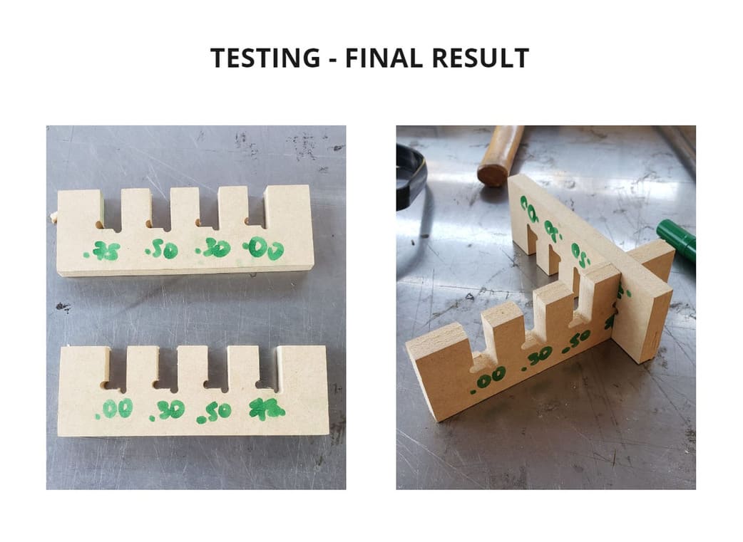
TESTING
After the cutting process was completed, I tested the parts with the sockets:
I gave the measurements of 15mm, 15.30mm, 15.50mm and 15.70mm, these are the data I obtained:
-
0.00 (15mm): Adequate, neither too loose nor too tight.
-
0.30 (15.30mm): Slightly looser.
-
0.50 (15.50mm): It is moderately loose.
-
0.70 (15.70mm) : Very loose
The perfect KERF was the 15mm (pictured as .00 in green) and this is the one I will be using for my individual assignment, as I will be using the same MDF board.
You can see the pictures below:
2. INDIVIDUAL ASSIGNMENT:
For this assignment I need to make something big and I made it 😅 one piece took up almost the entire workbench. More details below:
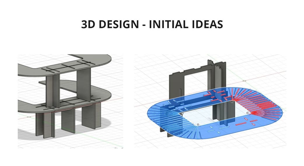
DESIGN
-
I started making sketches, but I wanted to add curved shapes to my design, so I made a mock-up model with cardboard in 1/10 scale, making the curved shapes and support structure.
-
Then I started to design in FUSION 360, I indicated the measures, but it was complicated to make the curved volume, so I made the central piece in a flat shape but with the necessary design so I can make the curves.
-
To make the shape curved, I started from the radius of each corner and began to make strokes according to that. Finally I added a prudent space from which the end mill can cut without any problem.
-
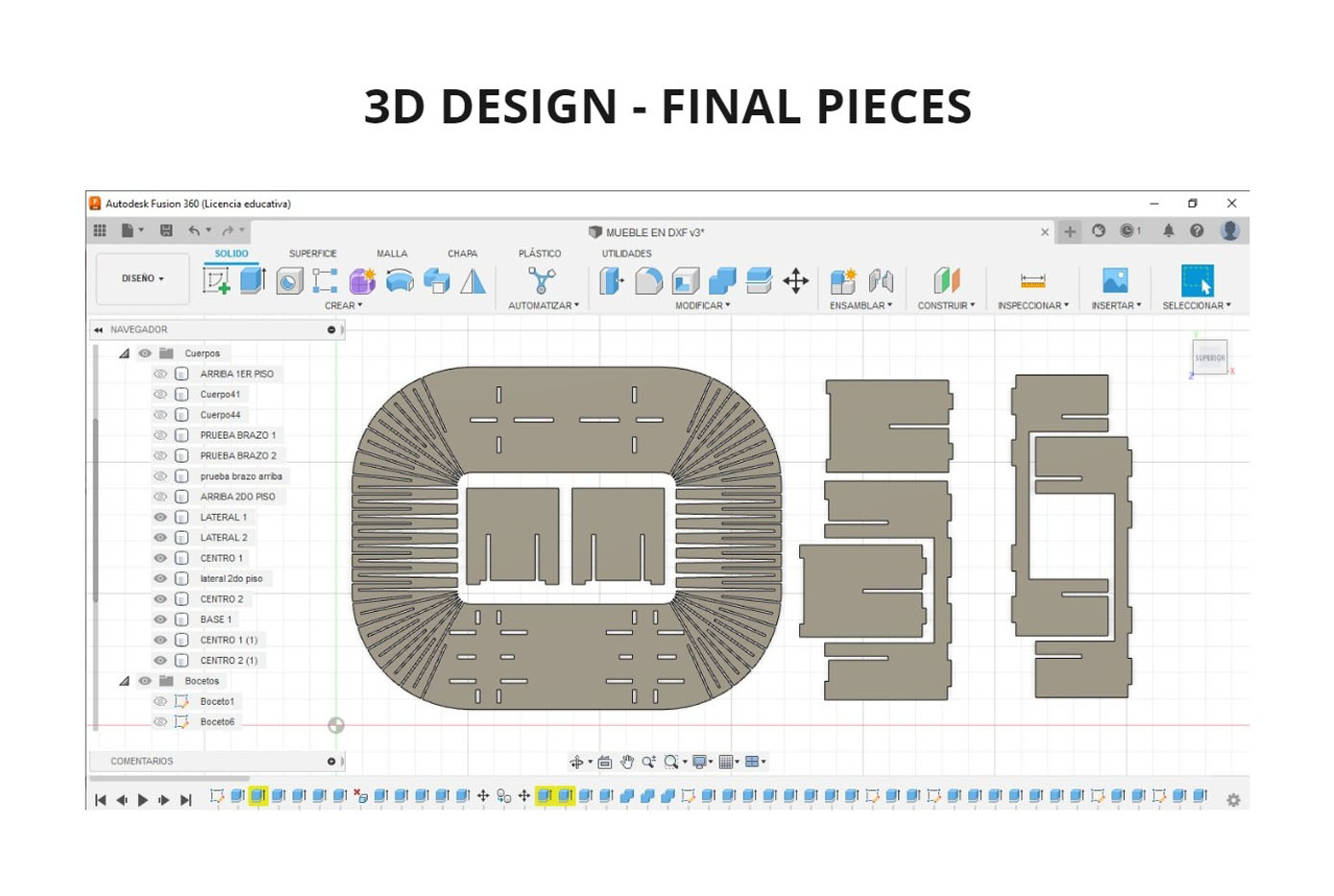
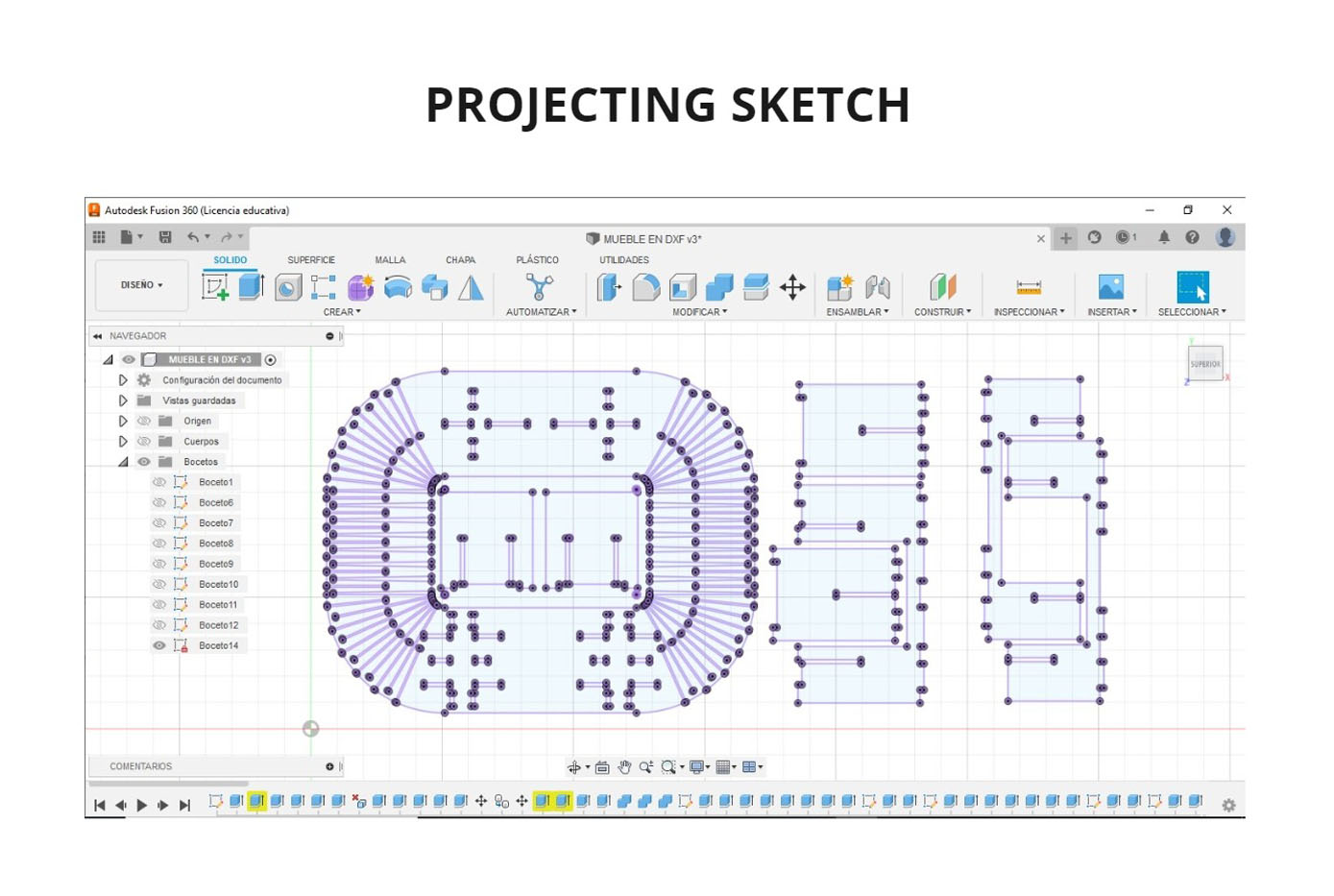
Finally, when I finished giving the exact measure to each piece, I placed all the volumes in the same height, this way I could project everything in a single layer, I followed the same steps that I did in Parametric construction kit and exported the design in
.DXF, so that it can be opened in theVCARVEprogram.
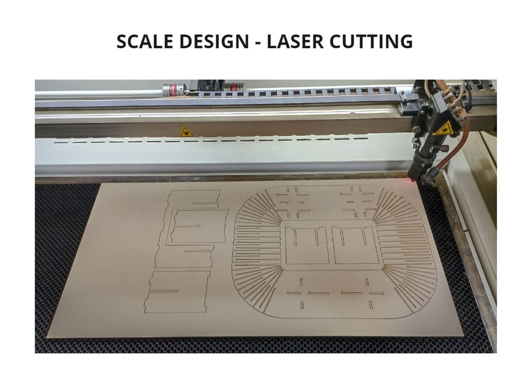
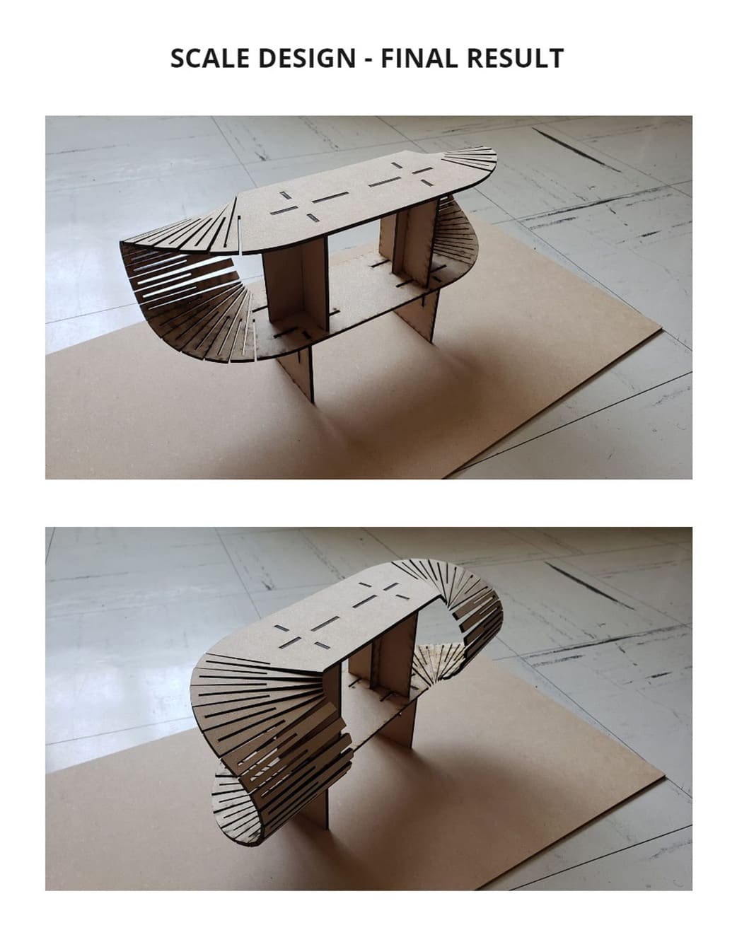
SCALE DESIGN
On the recommendation of my instructor, I scaled the design so that it could be assembled in 3mm MDF, this way I could check that the design would work.
So I did, I missed cutting 2 more pieces of the structure but it still worked, it was viable.
This is a method we can use to prove that a design is valid so we don’t waste material cutting on the CNC.
I show you the results:
SETTINGS
After importing my .DXF file into VCARVE, I followed the same setup steps as in the group assignment:
For the design I used the same 15mm KERF that was obtained from the group assignment, so there would be no problems in assembling my furniture.
The difference is that I made more than 1 Toolpath:
-
TOOLPATH 1: I named as interno_lesly, the
MACHINE VECTORSisINSIDE/LEFT, because the nd mill has a 1/4’‘ radius, eliminating that thickness during the tracing, this is the option for my internal strokes, it will remove the material without affecting my design. -
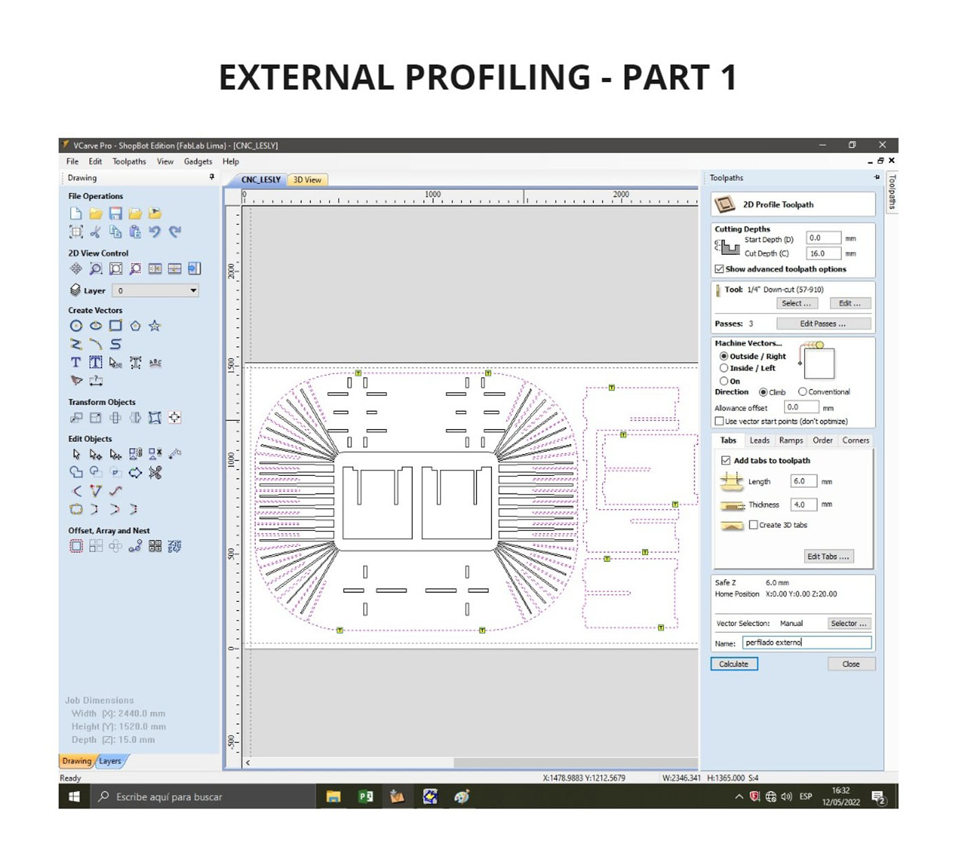
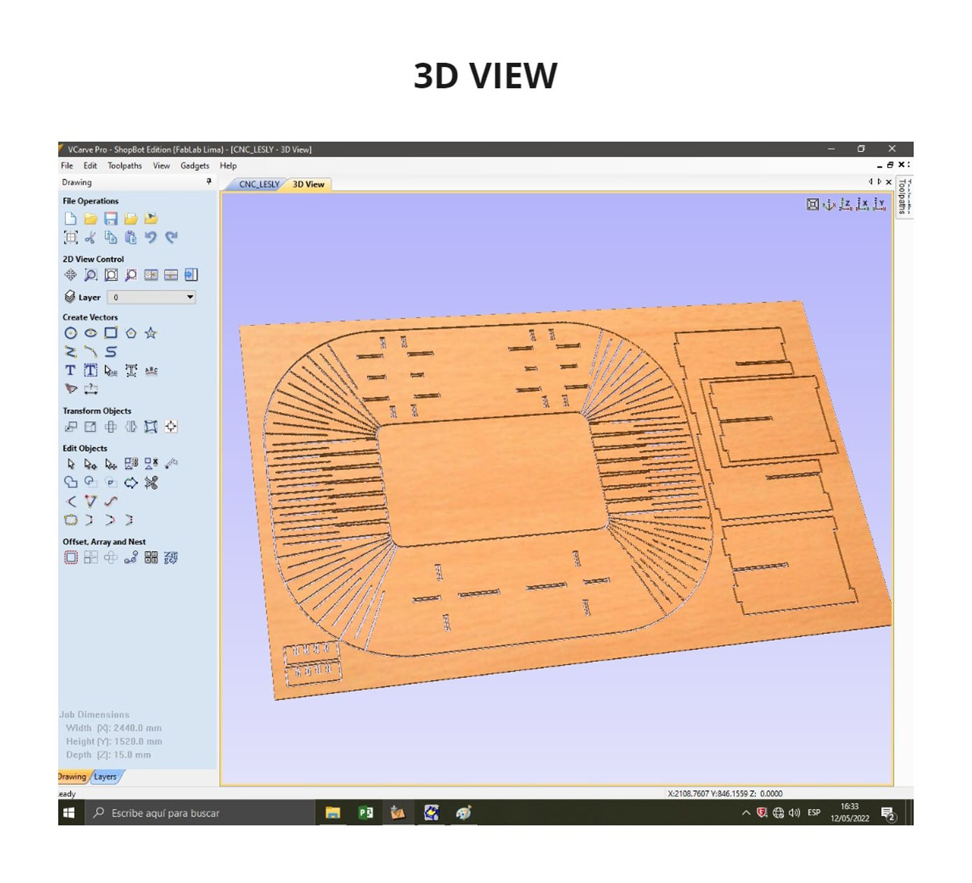
TOOLPATH 2: I named as externo_lesly, the
MACHINE VECTORSisOUTSIDE/RIGHT, because the end mill has a 1/4’‘ radius, eliminating that thickness during the tracing, but choosing OUTSIDE, the external trace will be maintained with the size we have designed. -
TOOLPATH 3: I named as externo_lesly_2, It is the same configuration as Toolpath 2 as they are external borders.
Another difference is that the toolpaths interno_lesly and externo_lesly, the depth I chose was 16mm, that is to say 1mm additional to the thickness of the material. The reason is that having many strokes and being some curved and others inclined can be more difficult to cut, with this additional millimeter I made sure that each piece is well cut.
For the toolpath externo_lesly_2 I only used 15.5mm depth because they were straight strokes.
You can see the configurations in the following photos and a 3D view of how the strokes looked in the material workspace:


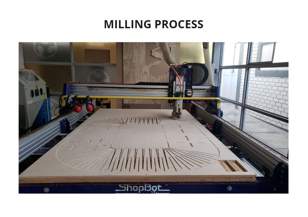
MILLING PROCESS
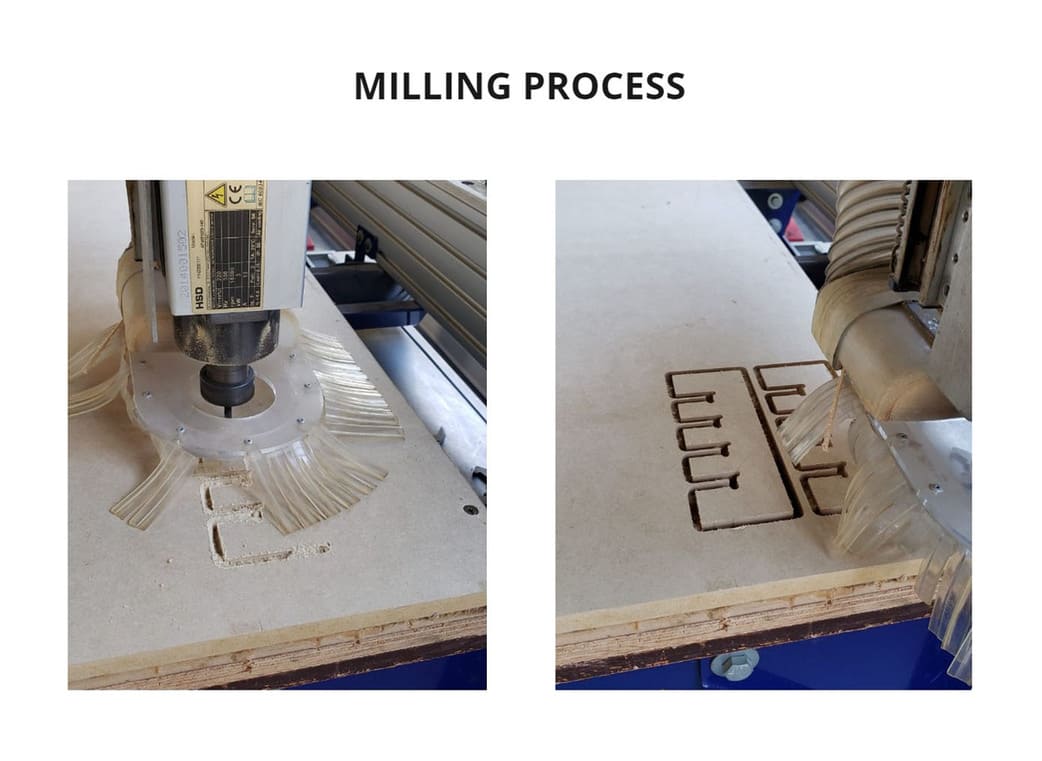
Remember that for this process the material must be bolted to the sacrificial bed to prevent it from moving during the milling process.
The design took up almost the entire MDF board and took a little longer in the parts that had curves and a lot of strokes.
You can see the process in the following photo:
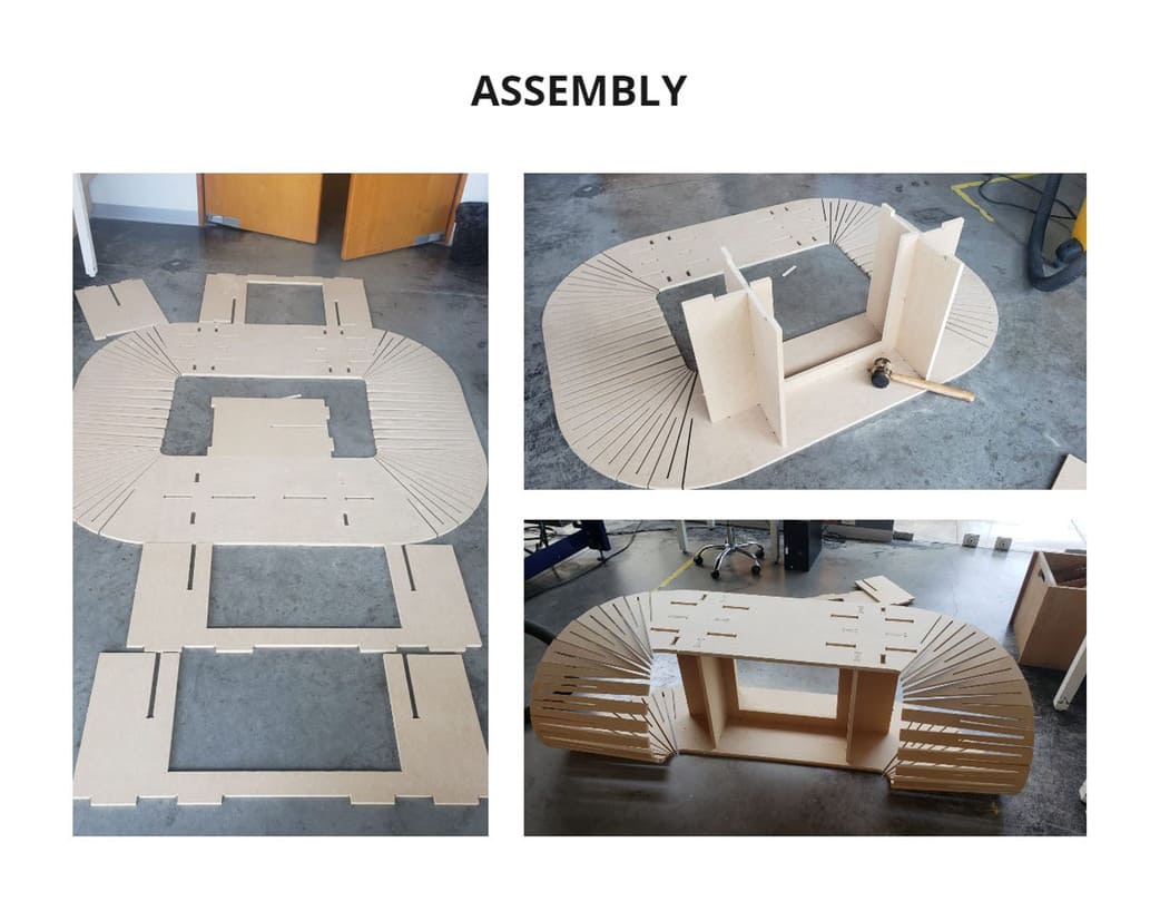
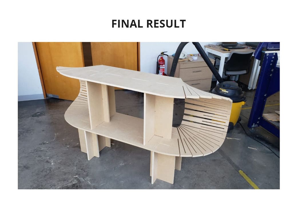
ASSEMBLY AND FINAL RESULT
When I finished cutting, I assembled the pieces with the help of a hammer, the hardest part was to bend the curve since it was only one piece, but it was done.
The pieces fit together and nothing broke! It can support the weight of several objects such as a printer, books, etc.
I wanted to take it with me but it’s too big and doesn’t fit on an average cart, so it’s on display at the Esan Fab Lab.
3. CONCLUSIONS
-
This CNC machine is a great help when you need to make large-scale structures with the highest possible precision, and it also reduces production time.
-
Always be aware of safety precautions, this is one of the most dangerous machines so be careful. There should always be someone else supervising the machine during operation.
-
Curved designs can be made, but taking into account the thickness of the nd mill.
-
Do pre-testing, this will help to make better fits and avoid wasting material.
-
If the material is very thick, I recommend doing it in several passes, so you won’t break the end mill and your project will have a good finish.