9. Embedded programming
Group assignment:
-
Compare the performance and development workflows for other architectures.
-
Document your work to the group work page and reflect on your individual page what you learned.
Individual assignment:
-
Read the datasheet for your microcontroller
-
Use your programmer to program your board to do something
1. GROUP ASSIGNMENT
This week, our instructor trained us about ARDUINO IDE and how to use program, understand how it works and be able to make our own codes. For the group assignment I had to learn how to use programs with different architectures and I show you below:
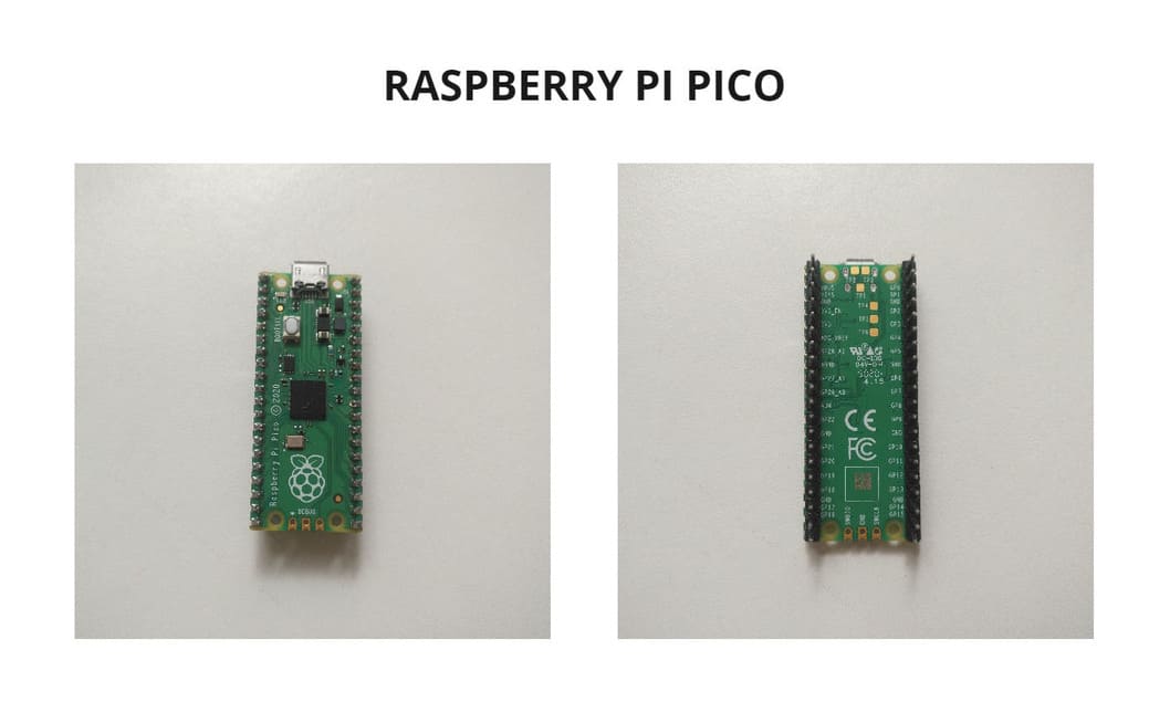
RASPBERRY PI PICO
Based on RISC architecture
Raspberry Pi Pico is a new low-cost, high-performance microcontroller board with flexible digital interfaces. You don’t use monitors or keyboards, but program them to take their input from, and send their output to the input/output pins. Using these programmable connections, you can light lights, make sounds, send text to screens, and much more. It is based on the Raspberry Pi RP2040 microcontroller chip.
Features:
-
RP2040 microcontroller with 2MB Flash (Dual-core cortex M0+ at up to 133MHz)
-
Operating Voltage : 3.3V
-
40 pin 21×51 ‘DIP’ style
-
3-pin ARM Serial Wire Debug (SWD) port
-
Micro-USB B port for power and data (and for reprogramming the Flash)
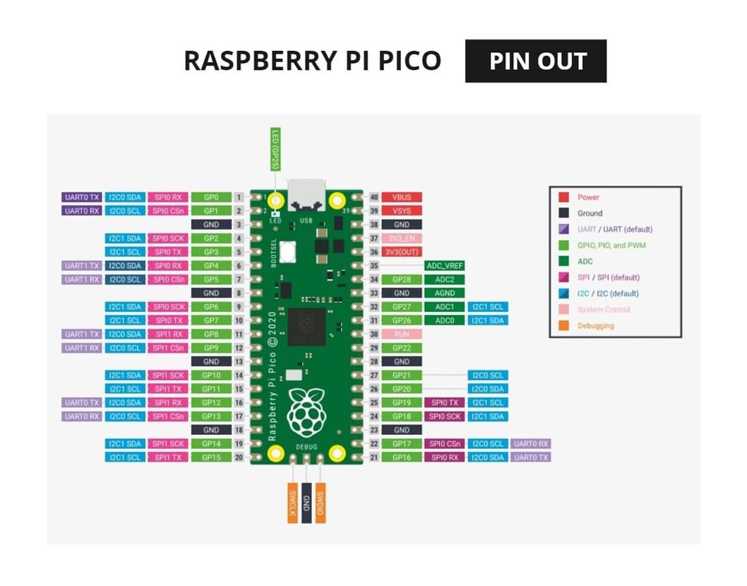
It has more details but I selected the ones I considered most important. I also leave you a PIN DIAGRAM so you have in mind which pins will be used for programming, as you can see the LED belongs to GP25.
First, I downloaded MicroPython UF2 file for Raspberry pico and followed the installation instructions.
Then, I downloaded Thonny IDE and installed it, this program is used to program the Raspberry Pi Pico.
If you would like to learn more about this topic, you can download the book MicroPython on Raspberry Pi Pico. There is very detailed information there about how to place the programming code in Thonny
-
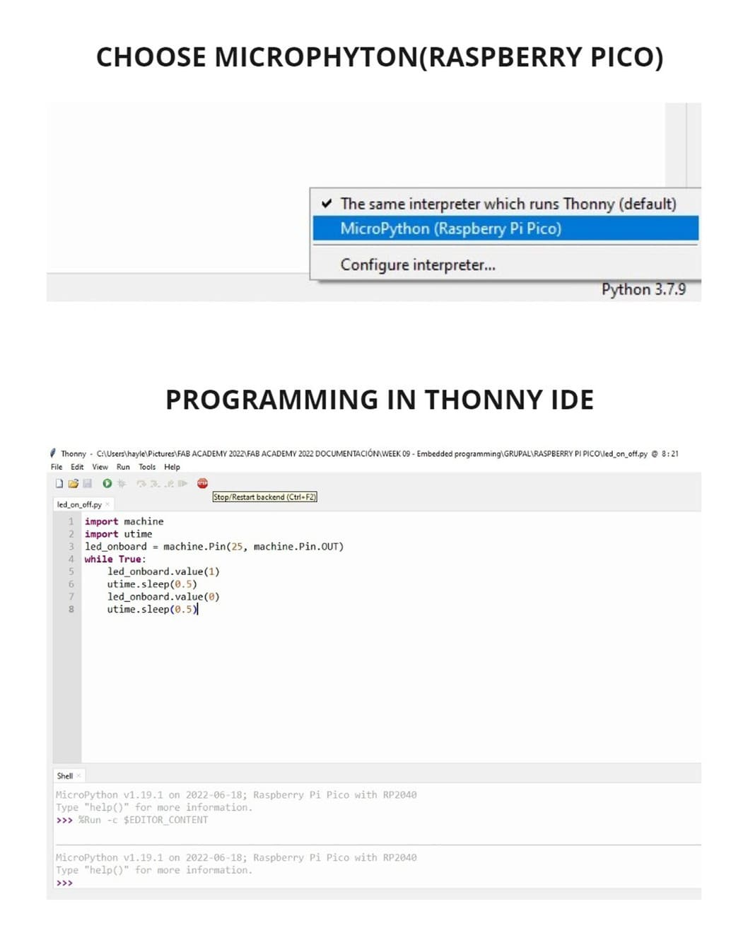
I opened Thonny IDE program and in the lower right corner clicked on
MicroPhyton(Raspberry Pi Pico) -
The code you see in the following image makes the LED turn on and off every
0.5seconds. The pin I used is25, since that belonged to the LED according to the PIN DIAGRAM, also you can see I placed two values,1and0, one is to turn on and the other to turn off. -
Click on green button to program.
-
Programming in Thonny has been very easy to understand, even the signs used are fewer compared to other programs.
-
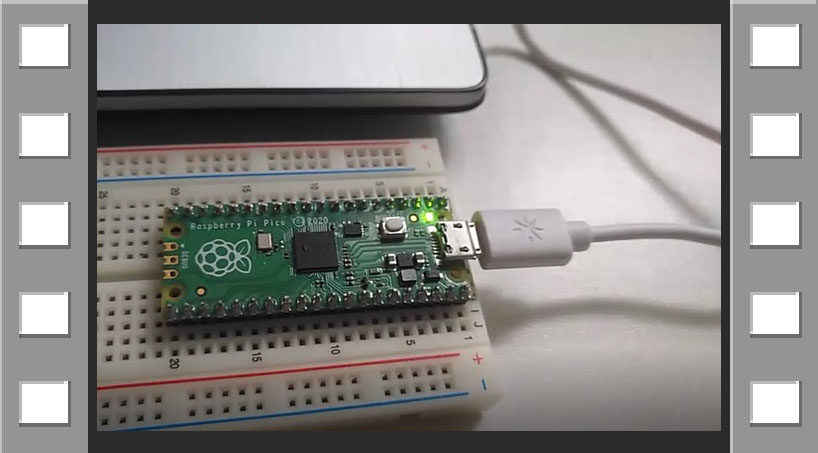
To see the results, you can watch the video below :
VIDEO

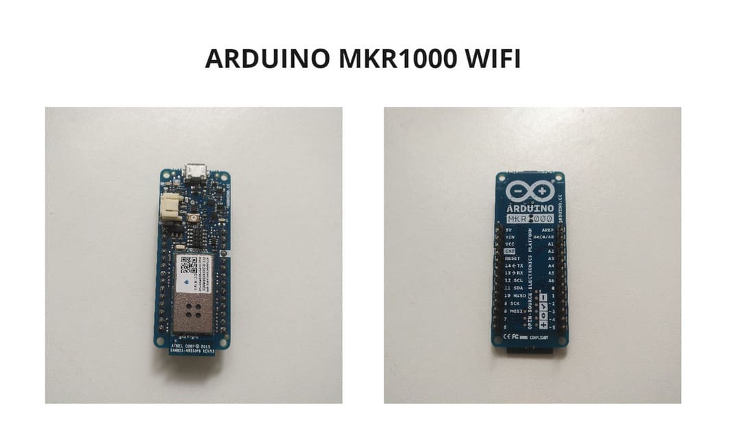
ARDUINO MKR1000 WIFI
Based on RISC architecture
It is a powerful board that combines the functionality of the Zero and the Wi-Fi Shield. It is the ideal solution for makers wanting to design IoT(Internet of things) projects with minimal previous experience in networking. It is based on the Atmel ATSAMW25 SoC (System on Chip)
Features:
-
Microcontroller: SAMD21 Cortex-M0+ 32-bit low power ARM MCU
-
Operating Voltage : 3.3V
-
Frequency (Clock Speed) 32.768 kHz (RTC), 48 MHz
-
ATECC508 crypto chip
-
Micro USB (USB-B) port
-
Built-in LED Pin: 6
-
Digital I/O Pins: 8
-
Analog Input Pins: 7 (ADC 8/10/12 bit)
-
Analog Output Pins1 (DAC 10 bit)
-
PMW Pins12 (0 - 8, 10, A3, A4)
-
External interrupts10 (0, 1, 4, 5, 6, 7, 8 ,9, A1, A2)
-
WIFI: ATWINC1500 (part of ATSAMW25 SoC)
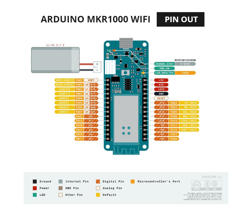
You can see more details in the following photos and PIN DIAGRAM:
First, you must have installed ARDUINO IDE depending on your operating system.
Then, to install the libraries, I used this QUICKSTART GUIDE:
-
Click on
QUICKSTART GUIDEbutton, then click on the version of Arduino IDE you have installed, I have Arduino IDE version 1.8, click onNEXTand follow the instructions. -
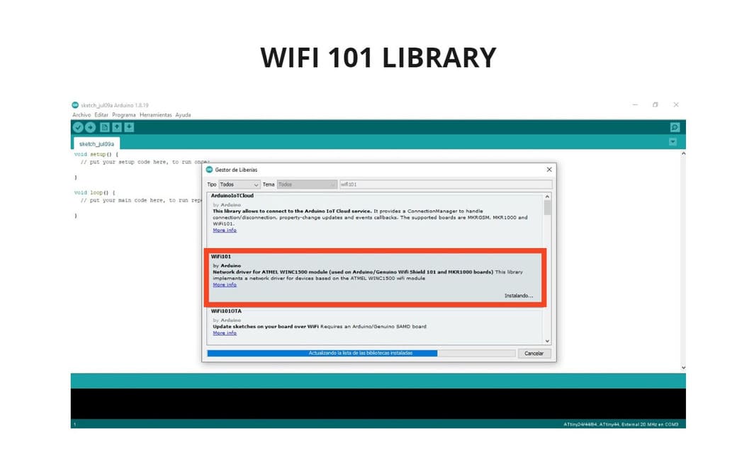
Go to:
SKETCH > INCLUDE LIBRARY > MANAGE LIBRARIES, writeWIFI 101and install it. This is the library we will need to drive the MKR1000 board -
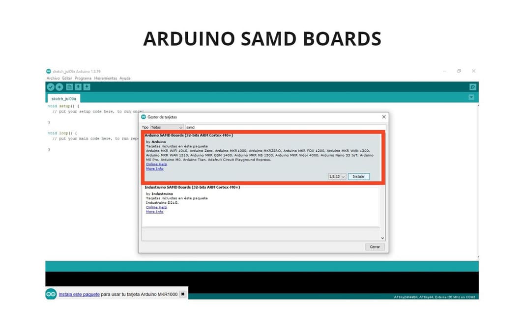
Go to :
TOOLS > BOARD > BOARD MANAGER, writeSAMDand installARDUINO SAMD BOARDS. Now we have what we need to configure our options and be able to program the board.
-
Connect the programmer to the PC and start setting up.
-
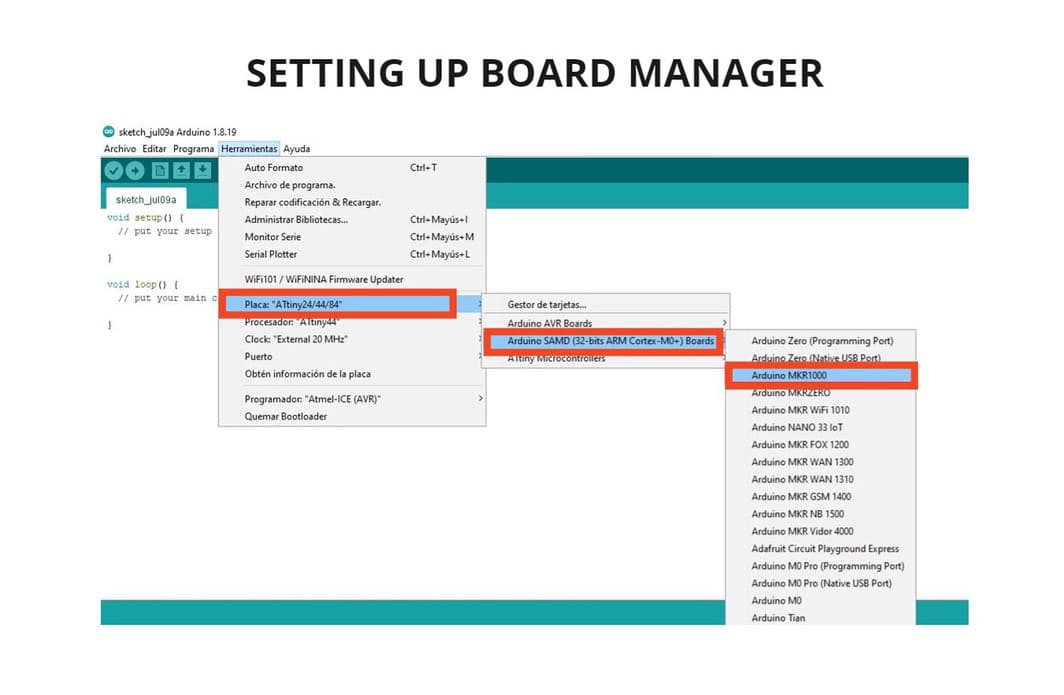
Setting up the board:
TOOLS > BOARD: ATTINY24/44/84 > ARDUINO SAMD(32-bits ARM cortex-M0+) BOARDS > ARDUINO MKR1000. -
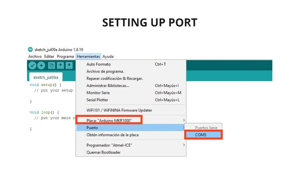
Setting up Port:
TOOLS > PORT > COM5. -
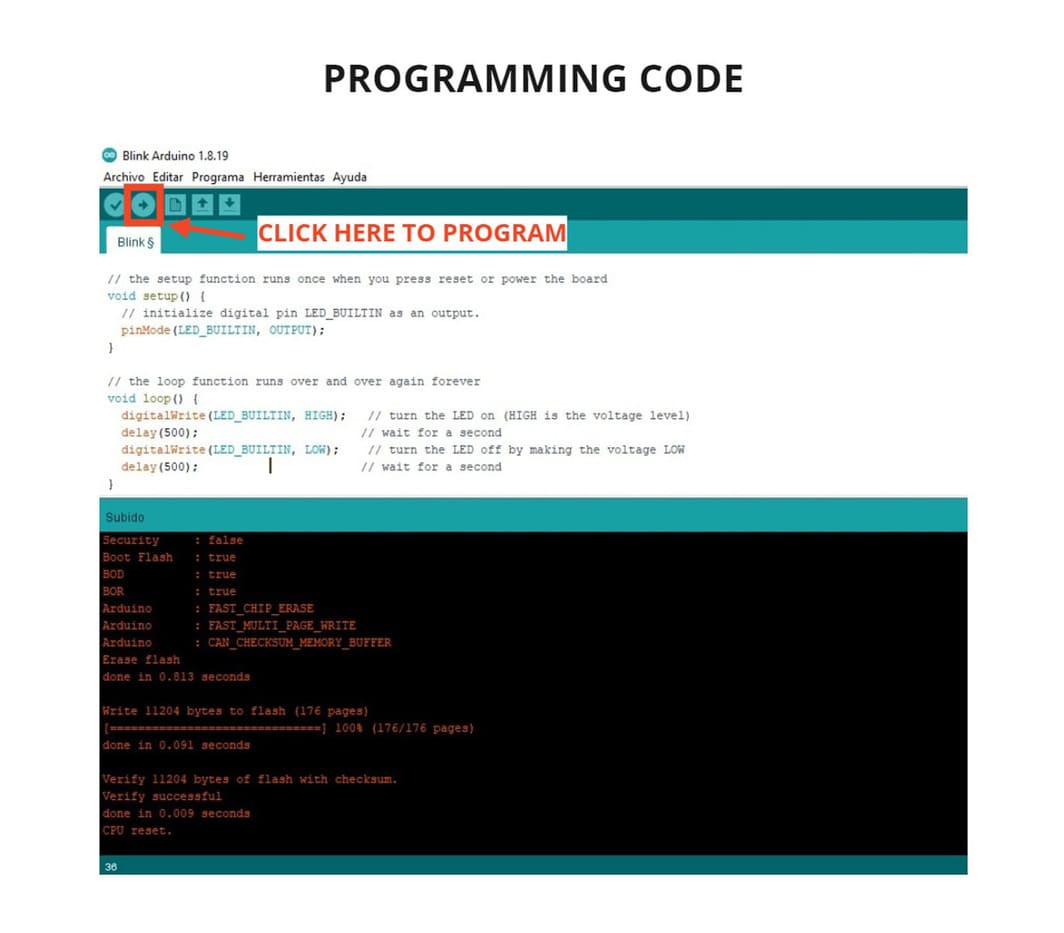
I decided to use an Arduino example, modify it and program it to make the board work. Go to:
FILES > EXAMPLES > 01.BASICS > BLINK.
-
Finally, I used the code and changed the
DELAYto500, this made the LED on the board blink every half second. -
The code looks very easy to understand, this is just one of the things that can be done with this type of board, there are more things to try and especially take advantage of the WIFI connectivity and I hope to do it in the future.
-
To program you must click the button that has an arrow pointing to the right, I have indicated it in the image below:
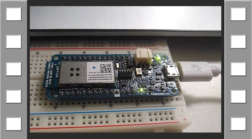
To prove that the programming was successful, I show you the video I recorded where you will see the result:
VIDEO

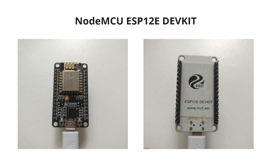
NodeMCU ESP12E DEVKIT
Based on HARDWARE Architecture
It is a WiFi embedded microcontroller board, effective in building IoT(Internet of Things) prototypes. Its has ESP8266-ESP12E WiFi based SoC(System on Chip) with NodeMCU firmware.
Features:
-
32-bit microcontroller at 80Mhz.
-
Frequency range : 2.4GHz - 2.5GHZ
-
Operating voltage : 3.3V
-
WiFi 2.4 GHz, support WPA/WPA2 Security
-
Support UART/GPIO data communication interface
-
Support update firmware remotely (OTA)
-
Support Smart Link
-
USB port onboard
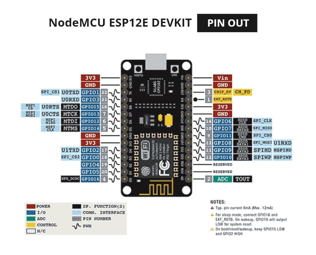
I took pictures of the board, you can see the detail on both sides and I also show you the PIN DIAGRAM so you can see in detail how it is distributed and its functions:
To use it, I followed this tutorial: The First Usage of NodeMCU ESP12E
-
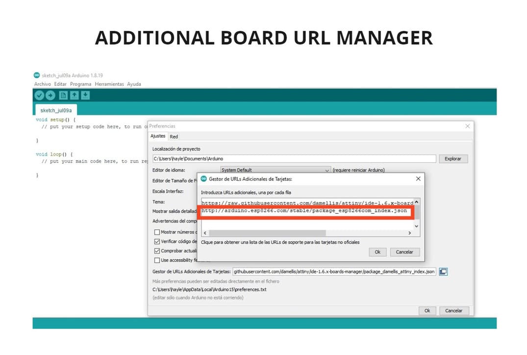
First, I installed a board manager needed for ESP12E, you can copy this URL:
http://arduino.esp8266.com/stable/package_esp8266com_index.json. Then, go to:FILE > PREFERENCES > ADDITIONAL BOARD URL MANAGERand paste the URL there. -
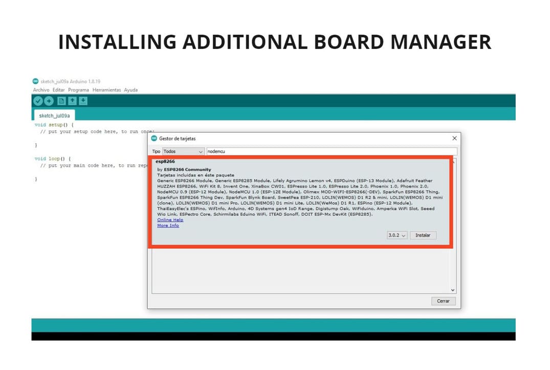
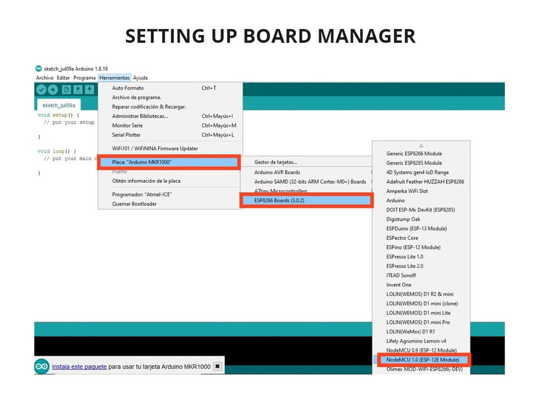
Then, go to
TOOLS > BOARD > BOARD MANAGERand writeNODEMCU, installESP8266.
-
Connect the programmer to the PC and start setting up.
-
Setting up the board:
TOOLS > BOARD: ARDUINO MKR 1000 > ESP8266 BOARDS(3.02) > NODEMCU 1.0(ESP-12E MODULE). -
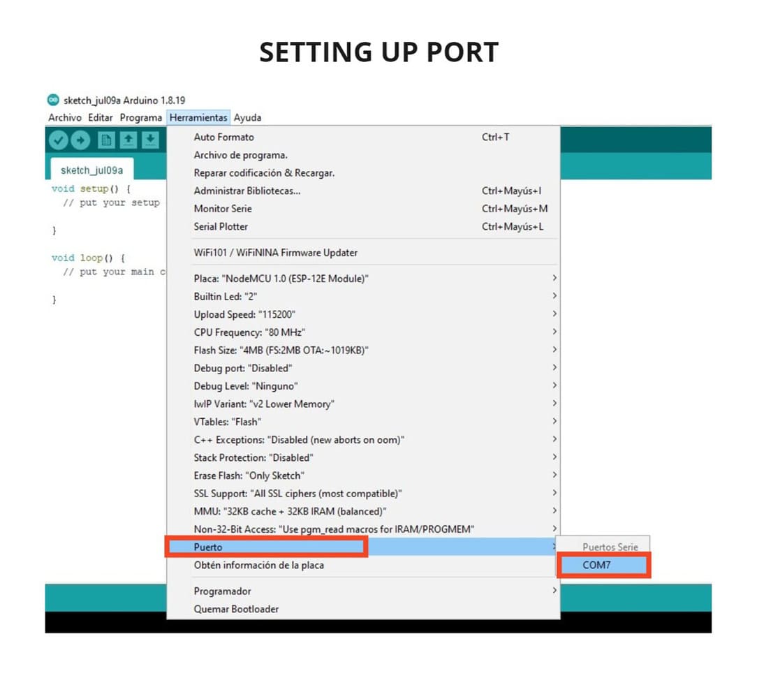
Setting up port:
PORT > COM7 -
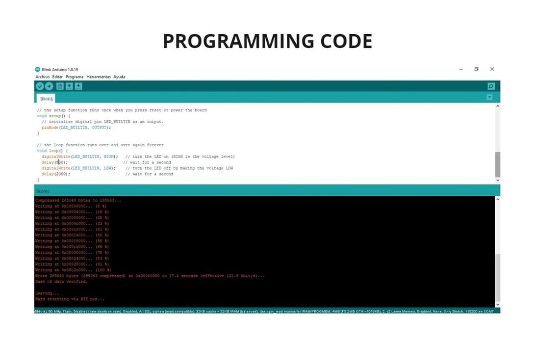
I decided to use an Arduino example, modify it and program it to make the board work. Go to:
FILES > EXAMPLES > ESP8266 > BLINK.
- I changed the
DELAYto500and2000, according to the programming it is supposed to be 0.5 seconds on and 2 seconds off, but the opposite happened, it means it is inverted and should be taken into account when programming.
You can see the code I used and modified in the following image:
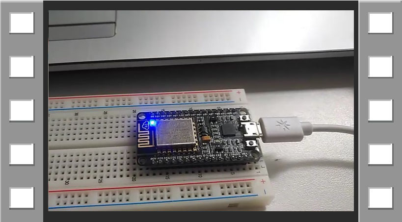
To prove that the programming was successful, I show you the video I recorded where you will see the result:
VIDEO

-
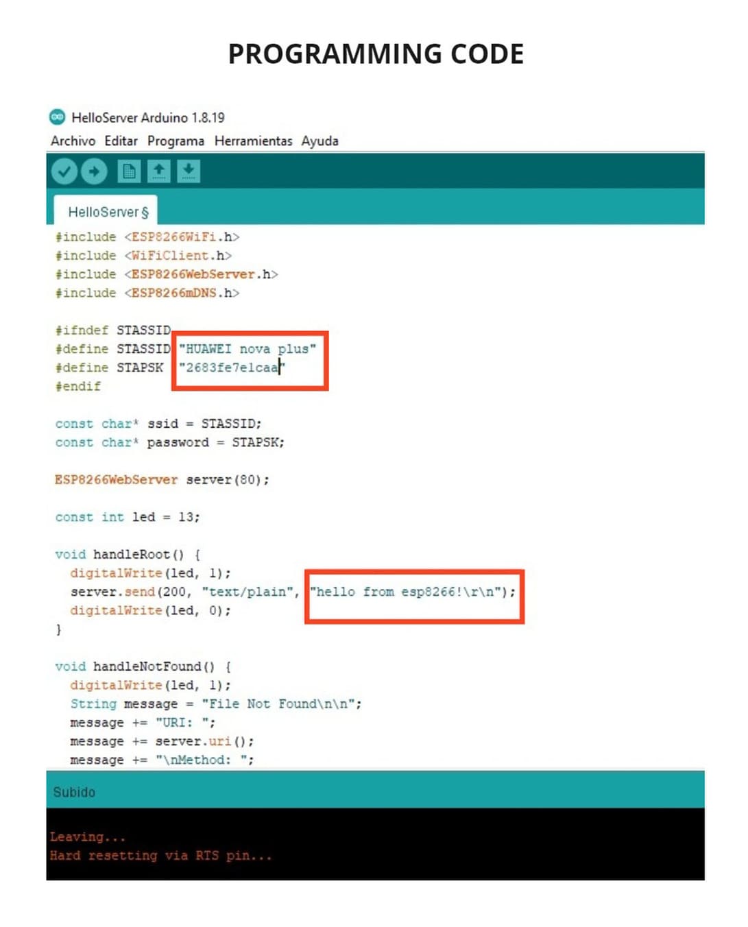
I used an example to programm, go to :
FILES > EXAMPLES > ESP8266WEBSERVER > HELLOSERVER. -
I modified and added the network
HUAWEI nova plus(which is the wifi network of my phone) and put the password which is2683fe7e1caa, this way it will connect via WIFI. -
You can also see the sentence
hello from esp8266!, this message will be seen when you open the internet browser if all the connection is correct.
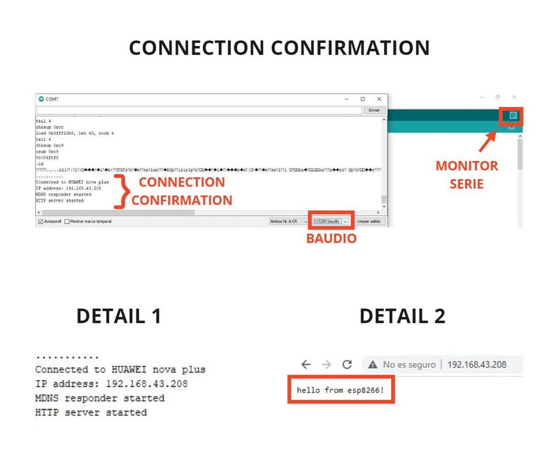
How to confirm that everything is well programmed and working?
After clicking on program (button with arrow that goes to the right), click on SERIAL MONITOR and you will get a new window, choose 115200 BAUDIO which is the one where the connection should be found.
Finally you should see the connection confirmation as you will see in the image of DETAIL 1, it took a while to connect but it was possible, you have to take into account that the computer must also be connected to the same WIFI network, in my case HUAWEI nova plus.
Finally, the IP address shown in the image of DETAIL 1, you must place it in the browser, give ENTER and the message hello from esp8266! will appear as you can see in the image of DETAIL 2.
2. INDIVIDUAL ASSIGNMENT
A few weeks ago I did the Electronic Design assignment, but something I didn’t go deep into is the microcontroller and its parts, it is very important to know at least the basics to avoid failures during design and programming.
We will also see the programming in detail and how to use the Arduino IDE Software for an Attiny 44 microcontroller.
DATASHEET
First, we must keep in mind certain basic concepts before going to the data sheet:
WHAT IS A MICROCONTROLLER?
It is a programmable integrated circuit, capable of executing the commands recorded in its memory.
WHAT IS ATTINY 44?
Attiny44 is a low-power CMOS 8-bit microcontroller based on AVR’s enhanced RISC architecture.
Microcontrollers use pins, which can be visualized as terminals (shaped like little legs) and serve to transfer information, some of them can be digital pins, analog pins, VCC, GND or RESET.
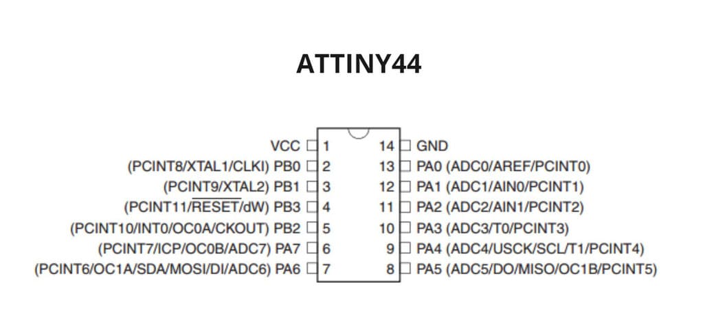
To know how to use the microcontroller we must take into account the datasheet, in my case I am using the ATTINY 44 and you can visualize the complete datasheet in the following link:
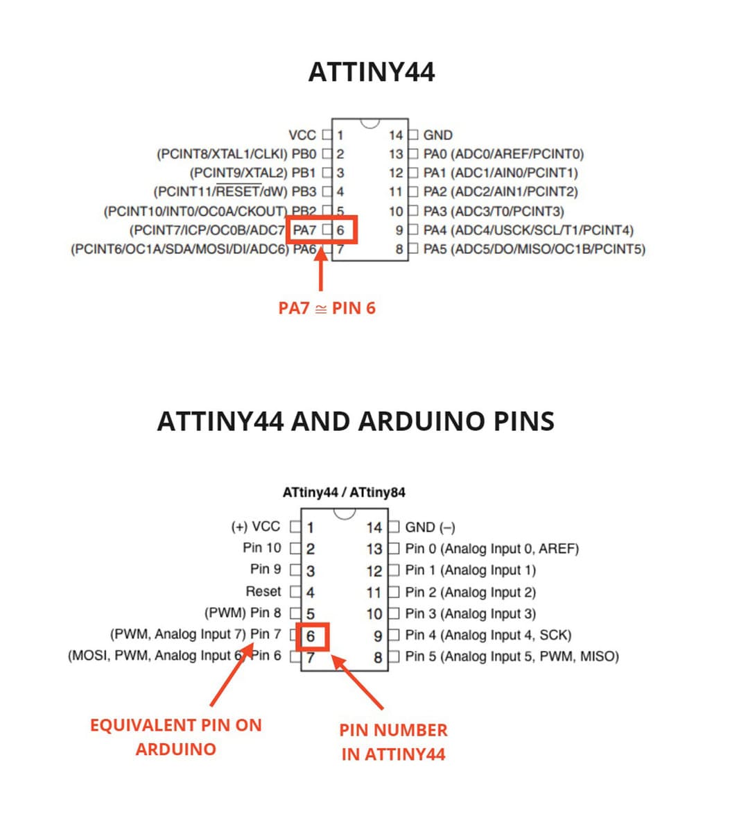
The image below shows the pins and their available functions:
FEATURES:
Low Power AVR 8-Bit Microcontroller
Architecture: Advanced RISC
4K Byte of In-System Programmable Program Memory Flash Programmable Watchdog Timer with Separate On-chip Oscillator
OPERATING VOLTAGE: 2.7 - 5.5V
I/O AND PACKAGES: 14-pin SOIC, PDIP and 20-pin QFN/MLF: Twelve Programmable I/O Lines
SPEED GRADE: 0 - 10 MHz @ 2.7 - 5.5V, 0 - 20 MHz @ 4.5 - 5.5V
PINS:
-
VCC: Supply voltage.
-
GND: Ground
-
RESET: This pin performs the function of restarting the whole process from scratch.
-
PORT B: is a 4-bit bi-directional I/O port with internal pull-up resistors. To use pin PB3 as an I/O pin, instead of RESET pin, program (‘0’) RSTDISBL fuse.
-
PORT A: is a 8-bit bi-directional I/O port with internal pull-up resistors. Port A has an alternate functions as analog inputs for the ADC.
Of the 14 pins, only 12 are programmable as I/O and these are divided into:
-
DIGITAL PINS: PA0, PA1, PA2, PA3, PA4, PA5, PA6, PA7, PB0, PB1, PB2, PB3
-
ANALOG PINS: PA0, PA1, PA2, PA3, PA4, PA5, PA6, PA7
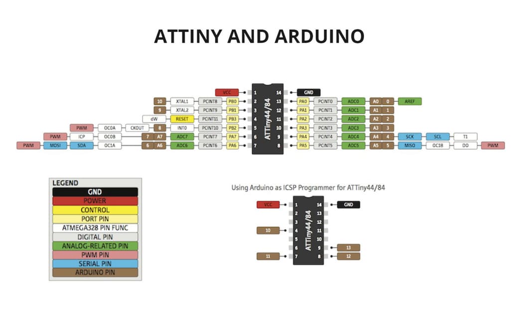
And as additional information, I show you an image of the equivalence of functions between an Attiny44 and ARDUINO. I used this image as a reference for later programming with the ARDUINO IDE.
There is something very important to keep in mind, a PIN can only fulfill one function at a time, if it is already programmed to work as a DIGITAL PIN, it can no longer be used as an ANALOG PIN.
You can see more detail and a better explanation in the programming section.
PROGRAMMING
To program we need to take into account the correct installation of libraries of our microcontroller and the code well typed according to the pins used.
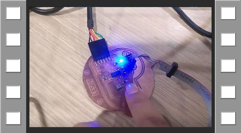
It is necessary to verify that the programmer and the board must be connected to the pc and among them.
Remember that the black color of the wire is connected to GND, as the following image:
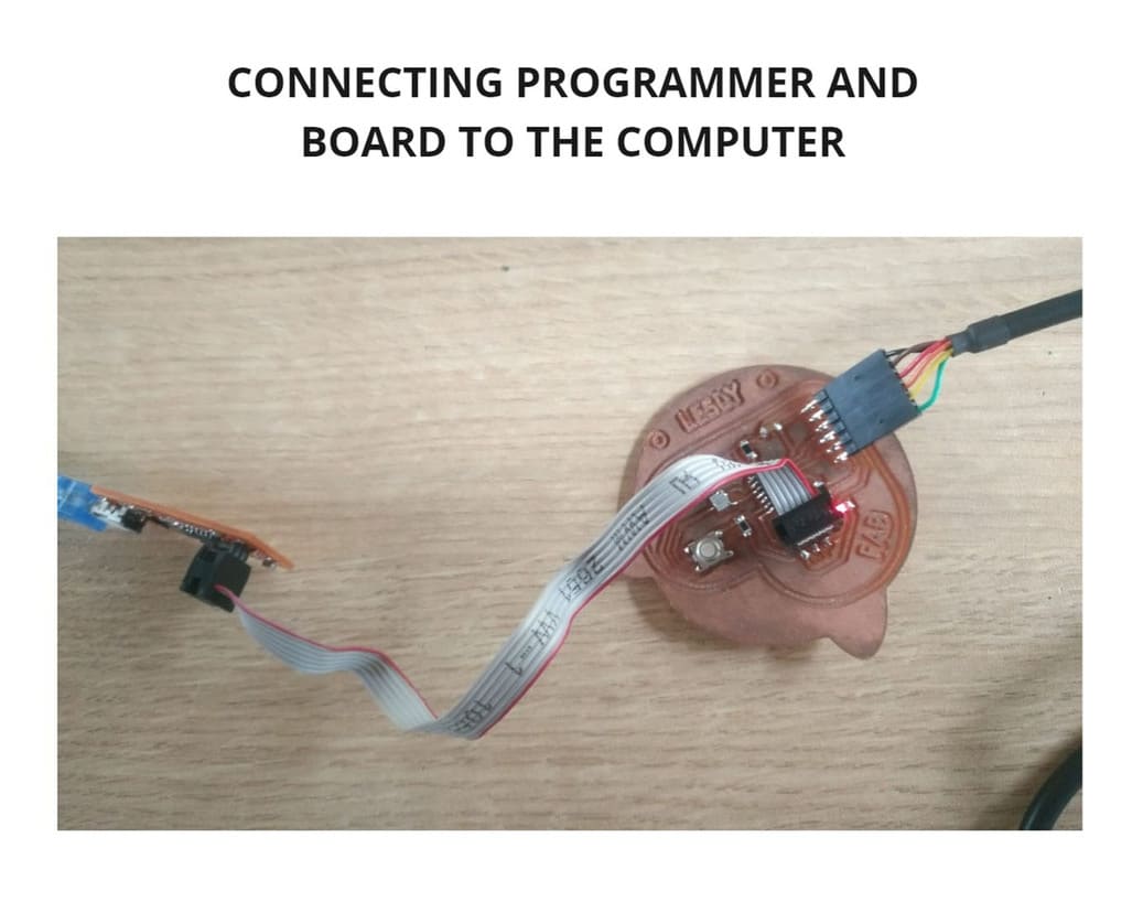
Join me for a closer look at every detail below:
LIBRARY INSTALLATION
To program we need to use a specialized Software, in this case I will be using ARDUINO IDE, follow the steps below:
-
Download and install the ARDUINO IDE software.
-
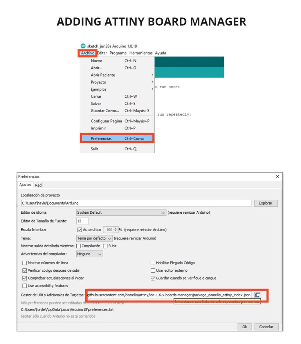
In order to program the microcontroller you must first add the path to the program. Click on
FILE>PREFERENCES. -
A new window will open and go to
ADDITIONAL BOARD URL MANAGER, there you must copy the following link: ATTINY-BOARD MANAGER and then click onOK. -
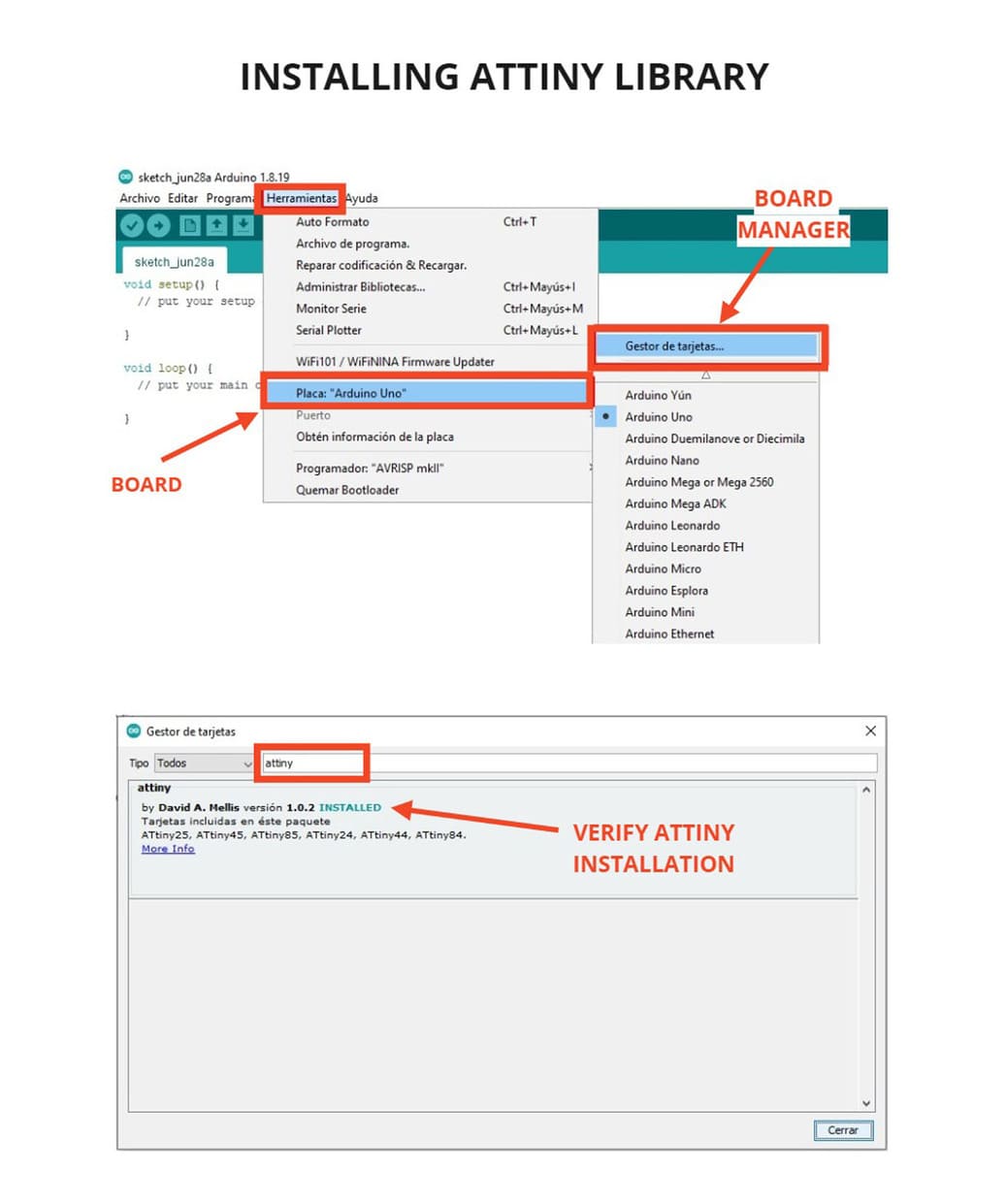
Click on
TOOLS>BOARD "ARDUINO UNO">BOARD MANAGER, a new window will appear, typeATTINYin the search box and you will see that there is a section containing different boards, this is the one I will use:ATTINY 44, then click onINSTALL, once installed you will be able to use it.
-
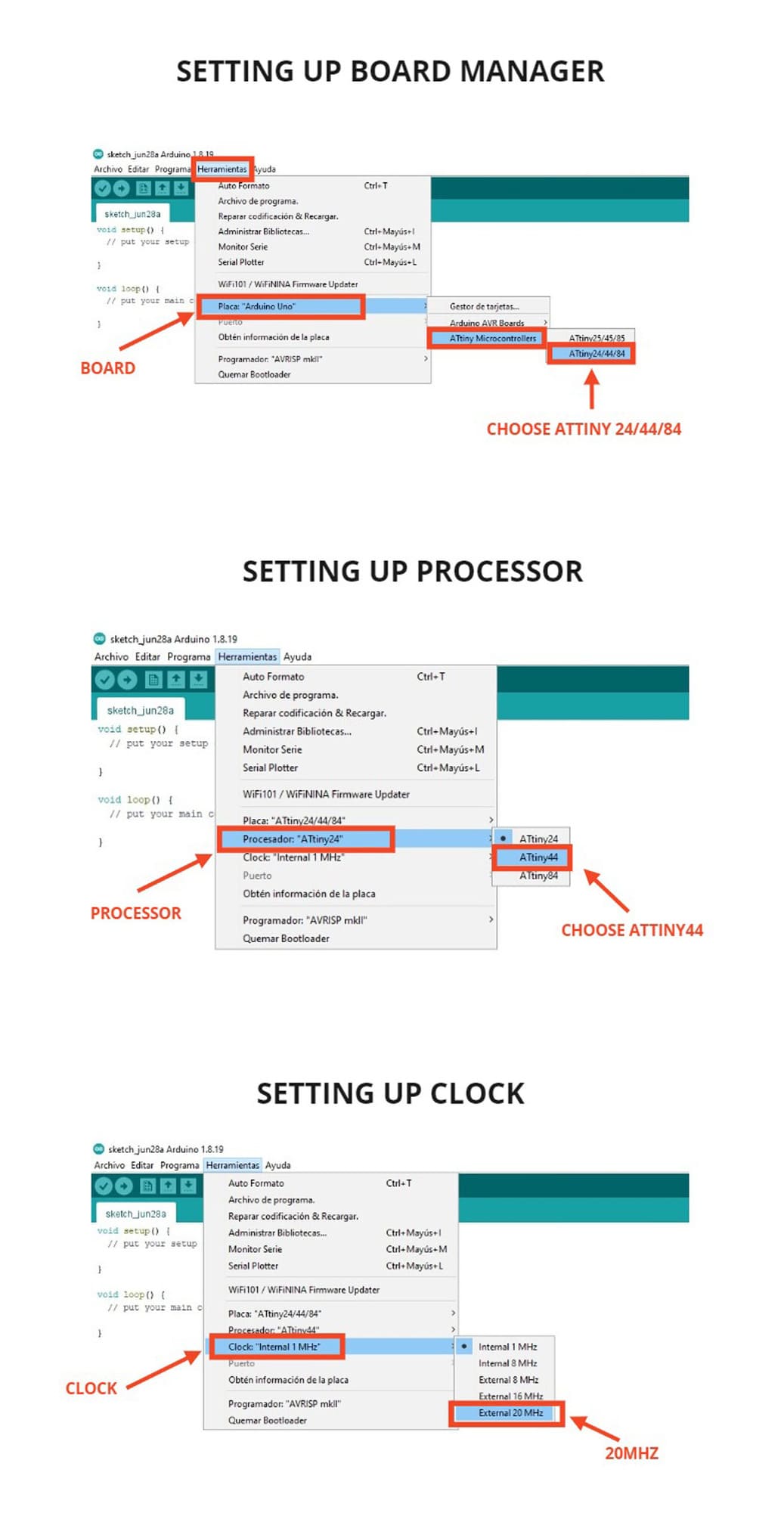
Go to:
TOOLS>BOARD "ARDUINO UNO">ATTINY MICROCONTROLLERS>ATTINY 24/44/84 -
Click on
PROCESSOR: ATTINY 24>ATTINY 44, my processor was not default in the ATtiny 44, that’s why I had to change it in this option. -
Next, click on
CLOCK: INTERNAL 1MHZ>EXTERNAL 20MHz, I made this change because I am using a 20MHz resonator, it all depends on the design and components you are using. -
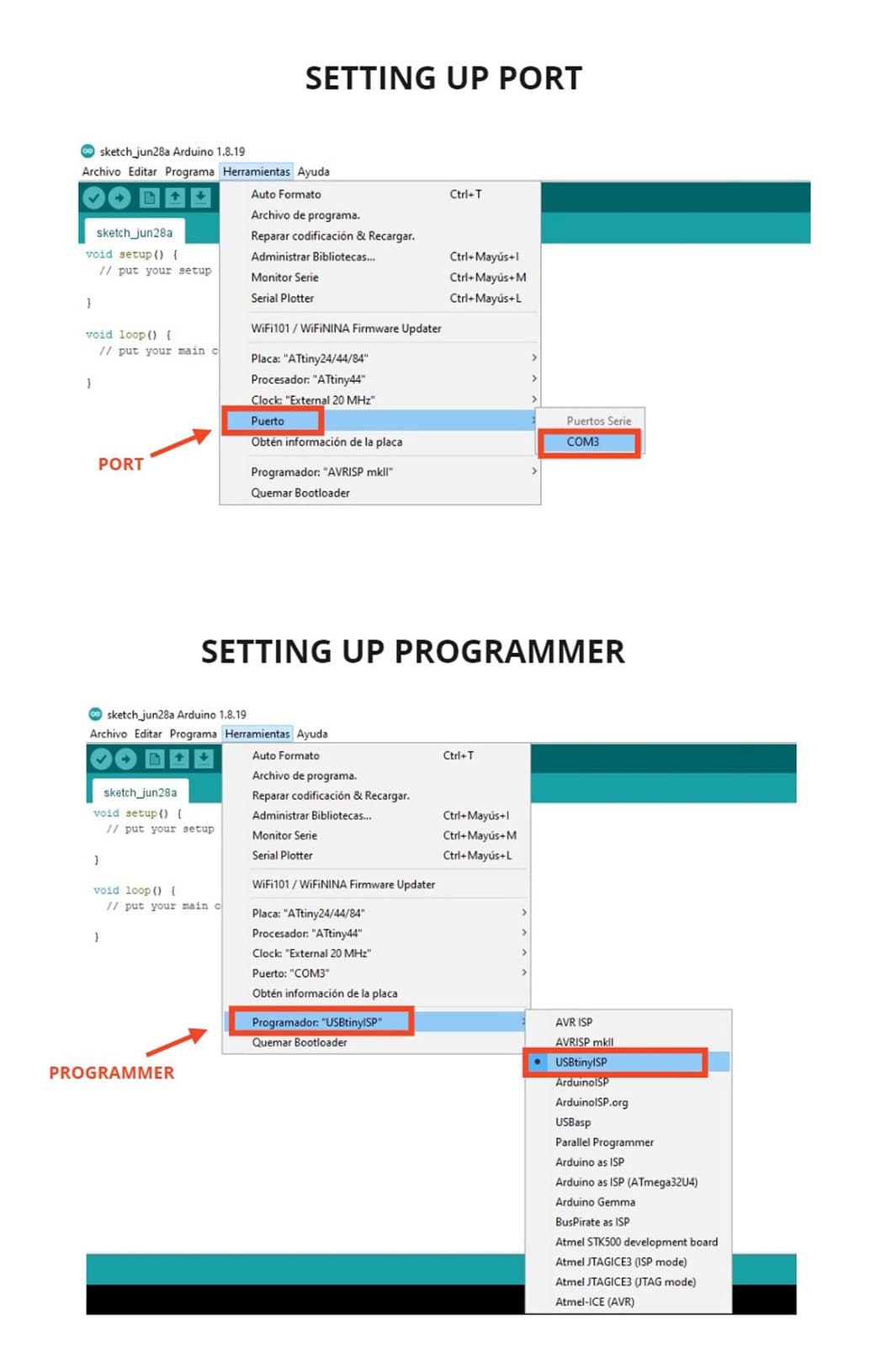
Click on
PORT, this should recognize theCOM3, which is the one I am using when connecting my PCB to the computer. -
Finally, in the programmer section, this option must be selected:
PROGRAMMER: USBtinyISP, this is the programmer I made on Electronic production’s week and the one I am currently using for programming.
SOURCE CODE
Now it is time to place the code and program. You must keep in mind that we are using ARDUINO IDE and the pins may have a different order for programming.
When you locate the VCC and GND input, it will help you to know the total pin order from 1 to 14 and you can find their equivalent in Arduino.
For example, the PIN 6 (PA07) of the Attiny will be represented as PIN 7 on Arduino for programming.
To help you to understand better, I show you the following schematic image where you can find the equivalent of each pin of the ATTINY 44 with Arduino.
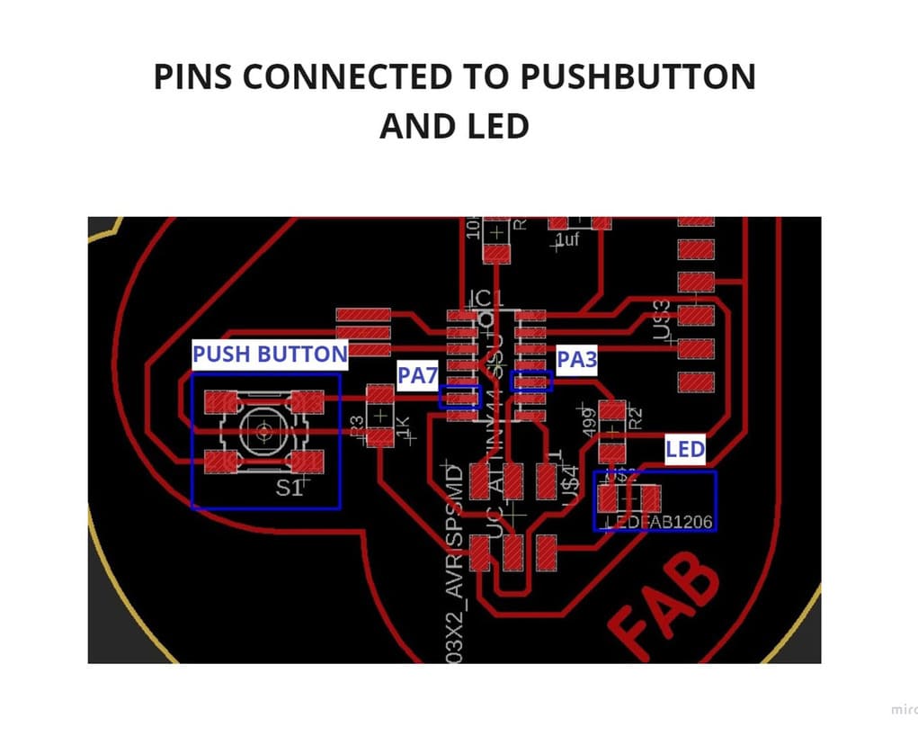
You can check your design and see the pins connected to the components that will program the LED and PUSH BUTTON, in my case this is the equivalence:
PUSH BUTTON : PA7 (PIN 6 ATtiny44) ≅ PIN 7 (Arduino)
LED: PA3 (PIN 10 ATtiny44) ≅ PIN 3 (Arduino)
You can see more details in the following image:
Now, we have the pins identified, it is time to place the code and program, I wrote the following code to program the board:
#define led 3
#define pushbutton 7
void setup() {
  // put your setup code here, to run once:
  pinMode(led, OUTPUT);
  pinMode(pushbutton, INPUT);
}

void loop() {
  // put your main code here, to run repeatedly:
  if (digitalRead(pushbutton) == HIGH){
    digitalWrite(led, HIGH);
  }
  else{
    digitalWrite(led, LOW);
  }
}
This is how it will look in the program:
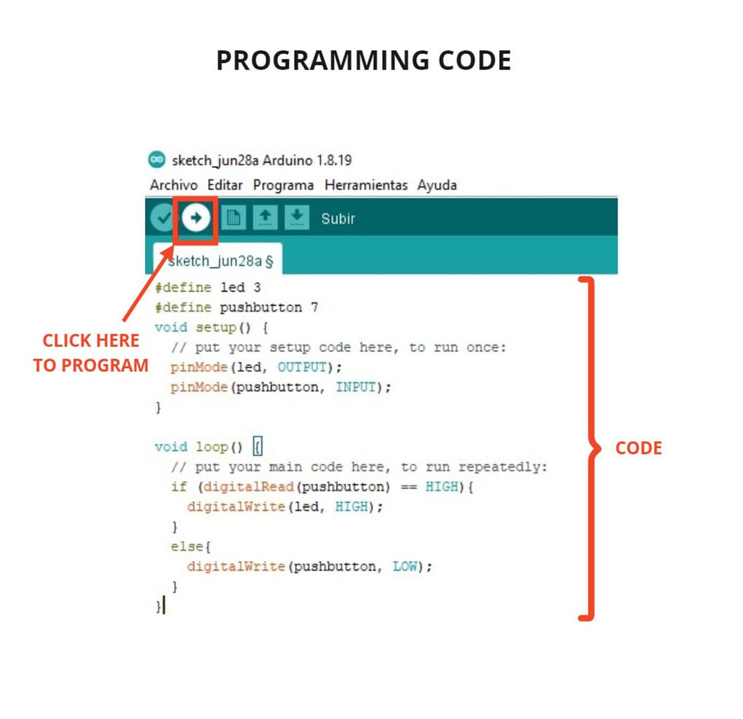
Indicating which pin performs a function is important because confusing just one word can cause you to see the ERROR message. I indicated that the pins used are digital, both the PUSHBUTTON and the LED and each one is assigned a function, what you see in the code means that when the PUSHBUTTON is pressed, the LED will be ON (HIGH) and when it is not pressed, the LED will be OFF (LOW).
You can try the code I have made and do your own test. Next you will see the video of the code working, at the end I made it in Linux because I had problems with the connection and I thought it was because of the operating system, but it was an error of value of a component, then I corrected and it worked very well:
VIDEO

3. CONCLUSIONS
-
Testing and programming different boards helped me to see that there is a long way to go in electronics, you can do different projects based on microcontrollers.
-
Arduino IDE is an easy to understand program and the codes are simple compared to other programs and can be used in Windows, Linux or MAC, it can also be programmed in other IDE software or in the Linux terminal, although some characters and also the way of programming vary.
-
Thony IDE is very easy to understand and I hope to use it in other raspberry projects.
-
Review the datasheet of your microcontroller will help you to locate and connect the components correctly, as well as program with the correct pins, especially if you use a program like Arduino IDE and you have to know the equivalent pins.
-
Check the connections with the multimeter after soldering the parts, so you can check if everything is well connected and soldered. If there is no sound indicating connectivity, you should check the soldering and add tin only if necessary (too much tin can be harmful and can join components that should not be together or burn any component).
-
Check the value of the components to verify if it corresponds to what you have designed, just make a mistake in the value of a component, can make the board not work.
-
Be sure to indicate well the programming code, define correctly the PIN that controls the Input or Output that you have added in your design, if the pin is incorrect, you will not be able to program.