4. Computer controlled cutting
Group assignment:
-
Characterize your lasercutter’s focus, power, speed, rate, kerf, and joint clearance.
-
Document your work to the group work page and reflect on your individual page what you learned.
Individual assignments:
-
Design, lasercut, and document a parametric press-fit construction kit, which can be assembled in multiple ways. Account for the lasercutter kerf.
-
Cut something on the vinylcutter.
Hello! This week we have learned about the use of the laser machine and the vinyl cutter, then we will see the different types of configurations of each machine and their results.
1. GROUP ASSIGNMENT
Here you can see the Grupal assignment
2. INDIVIDUAL ASSIGNMENT
I have made the vinyl cut as well as a parametric kit, see the process below:
VINYLCUTTER
There are many types of vinyl cutters, in this occasion, I am using the Cameo 4 from Silhouette.
CAMEO 4
The Cameo 4 is a desktop cutting machine for the modern maker. This machine can cut vinyl, cardstock, fabric, and more to create custom projects.
Features:
-
Maximum Cutting Area: 12 in. x 24 in. (30.5 cm x 61 cm) with a cutting mat / 12 in. x 60 ft. (30.5 cm x 3m) without a cutting mat
-
Maximum Media Thickness : 118.11 mils (3 mm)
-
Maximum Cutting Force : Carriage 1: 210 gf / Carriage 2: 5 kgf
-
Compatible Media Types: Vinyl, Heat transfer material, Cardstock, Photo paper, corrugated paper, Chipboard, Fabric, and more.
-
Interface: USB 2.0 high speed / Bluetooth
-
Unit Dimensions: 22.44 in. x 7.68 in. x 6.69 in. (57 cm x 19.5 cm x 17 cm)
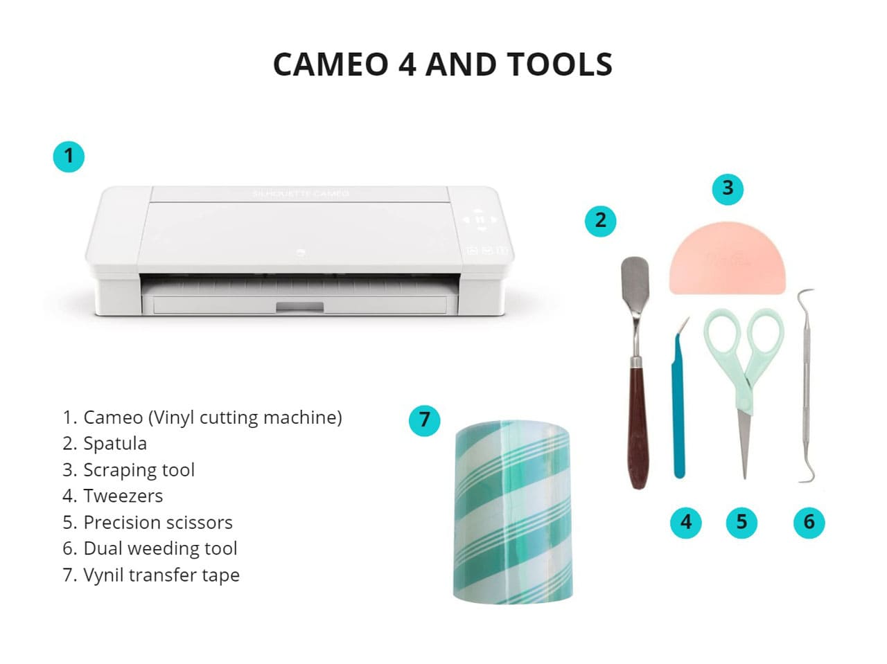
Tools:
Below I show you the CAMEO 4 and the tools that can help you to do a better job in vinyl cutting.
TESTING
To start, first we must have the image vectorized or as clean as possible, in this case, I used Illustrator.
Preparing file
-
I followed the same steps that I did during the Computer Aided design week to vectorize and save it in .PNG.
-
CAMEO 4 comes with Silhouette Studio software. I opened the image in
.PNGformat in this program. -
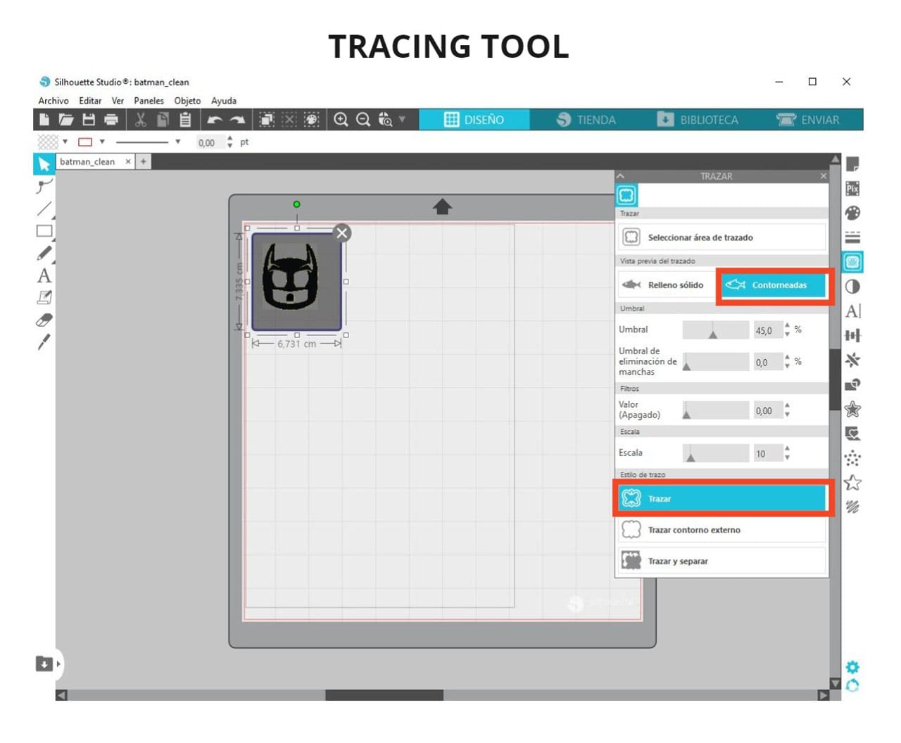
I used the
TRACING TOOL, is easy to find as it has a butterfly shape. I selected the entire image to be traced. Then I made click onCONTOUREDand finally click onTRACE. -
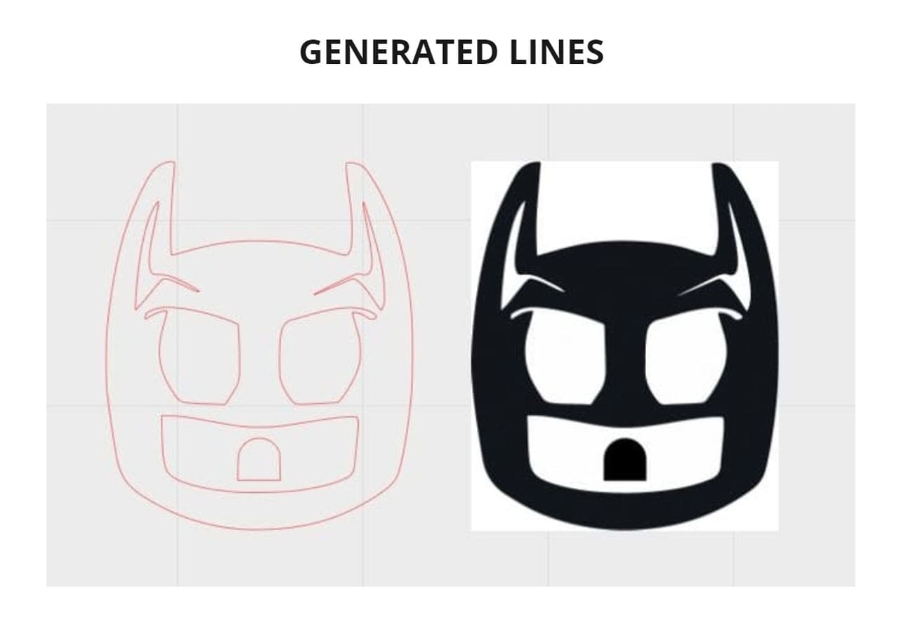
This generated lines that we can send to cut and you can separate the image from the lines with a single click. You have to remove the image from the cut area and leave only the traced lines.
-
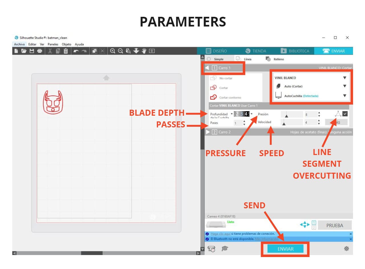
For the vinyl, I am using the parameters that you can see in the following picture:
Blade depth: 3
Pressure: 8%
Speed: 4%
Passes: 1
Line segment overcutting: check
IMPORTANT:
-
The machine only recognizes what is seen inside the cut area.
-
The parameters must be well configured before sending to cut, to avoid damage to the machine or material.
And that’s all, you just need to prepare the machine before clicking on SEND.
Preparing the machine and cutting
-
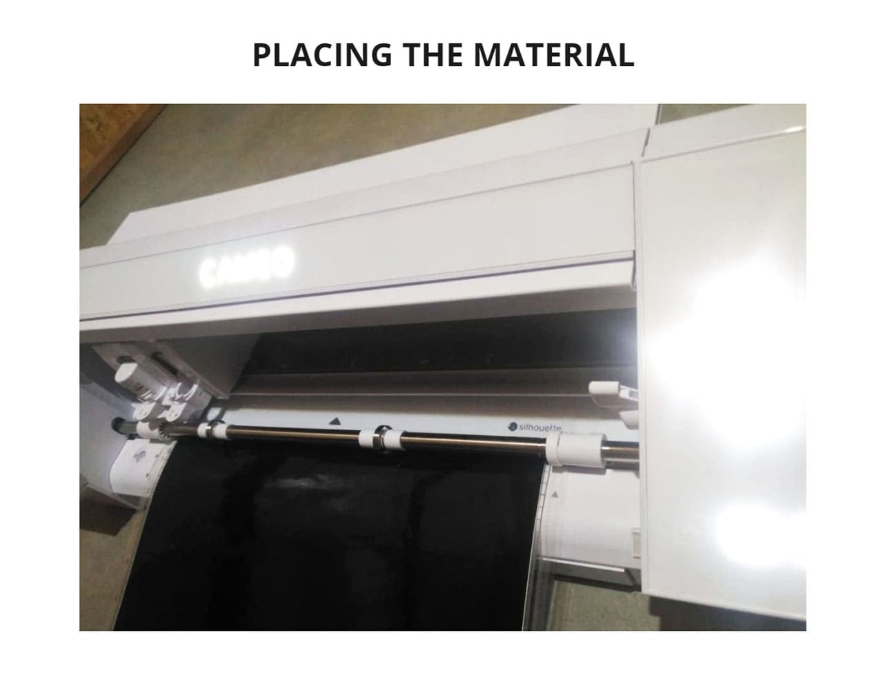
You need to place the vinyl on the cutting mat or use it rolled up, I chose the first option. Cameo 4 has buttons that help to position the material, you will use the upward-facing arrow like this:
▲, to to place the material. Cameo 4 can also be connected via bluetooth to your computer. -
Click on
SENDin the Silhouete program after the file has been prepared.. When the job is finished, click on the down arrow:▼and remove the cut vinyl from the mat, place it on a table. -
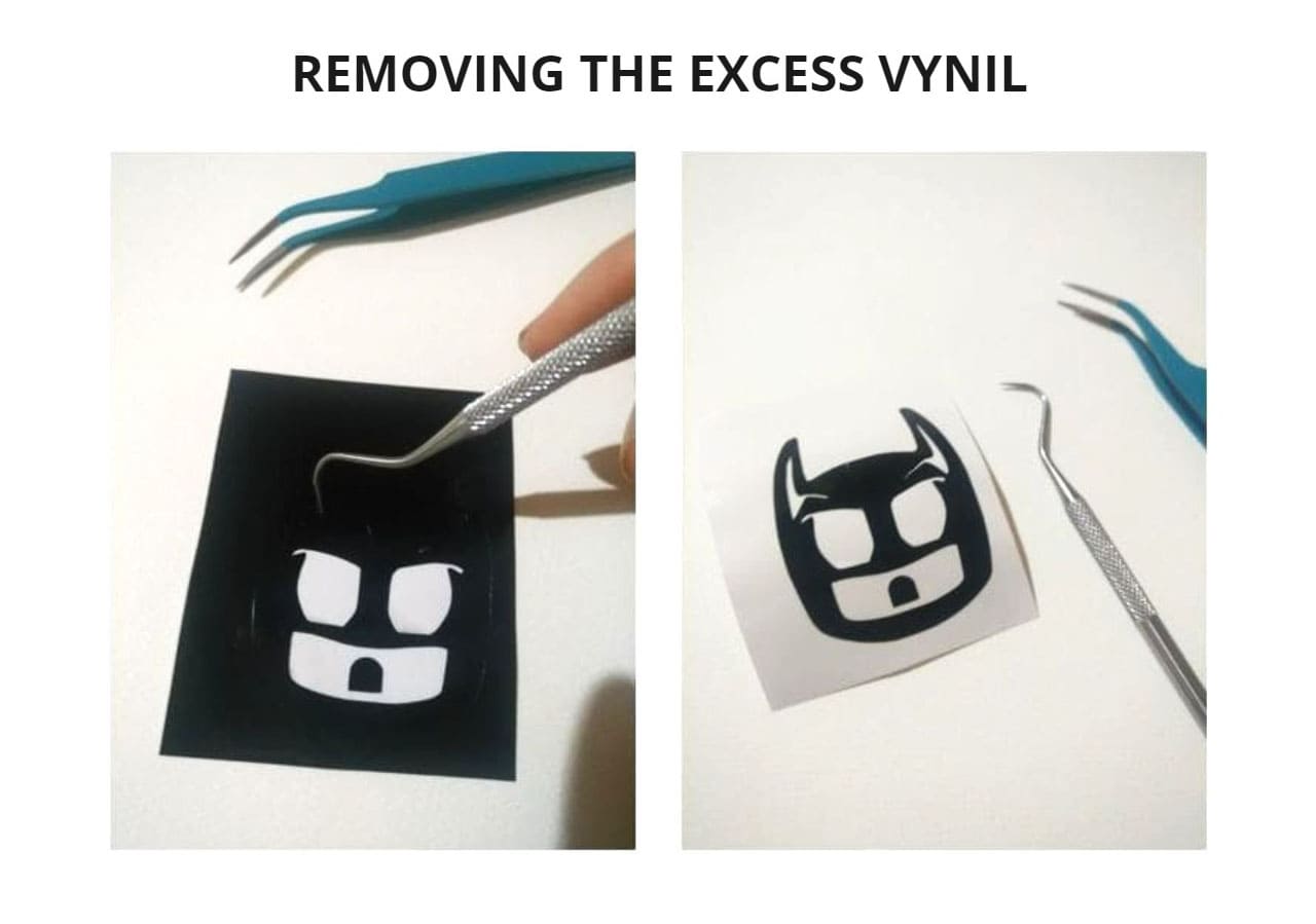
I used tools to help peel off the excess vinyl and then use the transfer tape to stick it on the desired surface (this way the shape and position of the cut figure is preserved).
-
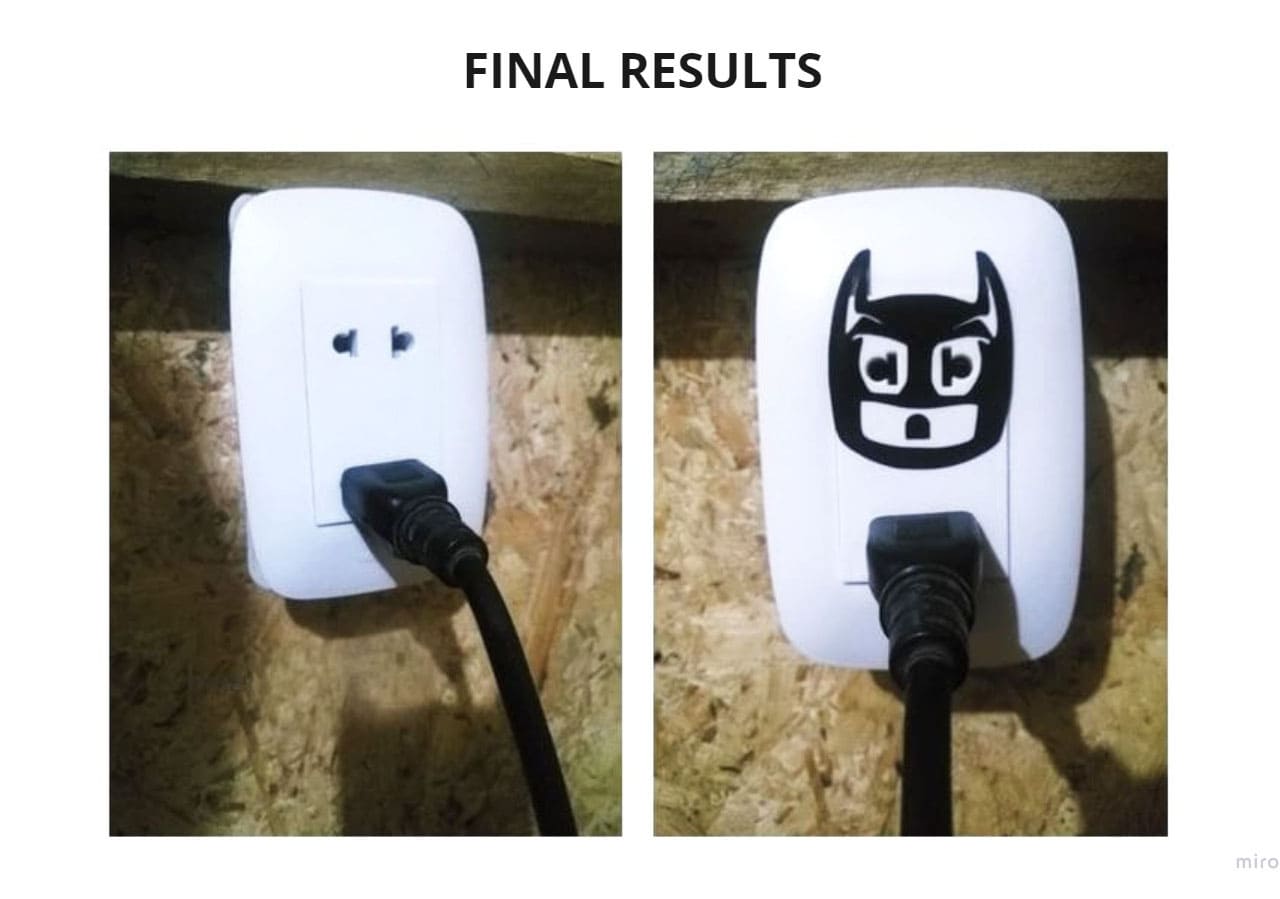
Finally, use a transfer tape for vinyl to place it on the surface where we want to stick it.
You can see the process and the result in the following photos:
Other designs
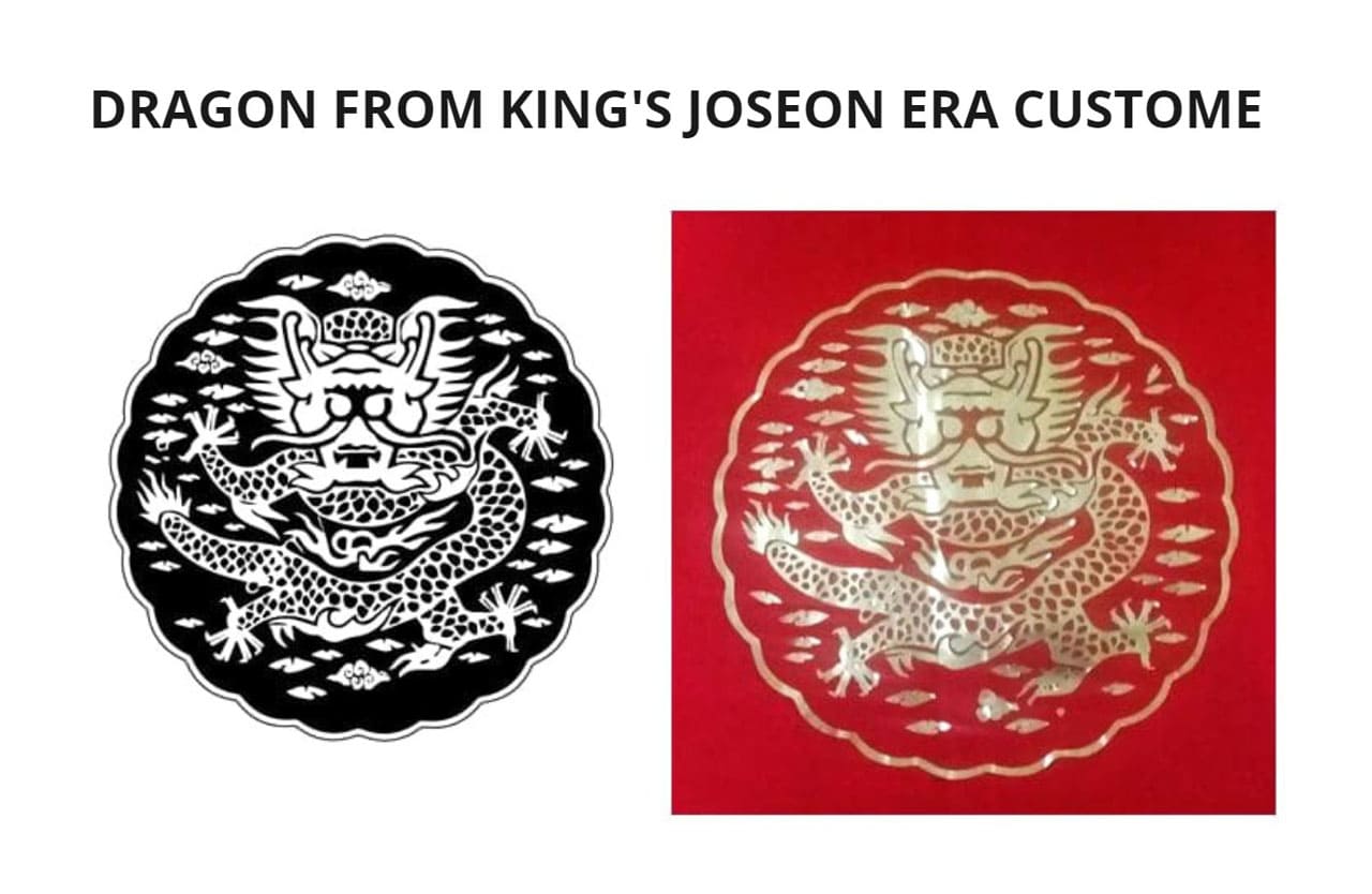
Following the same steps, use gold vinyl to cut other designs:
-
Dragon from the King’s Joseon Era costume, I cut it in gold vinyl and glued it on a coat in the style of the King.
-
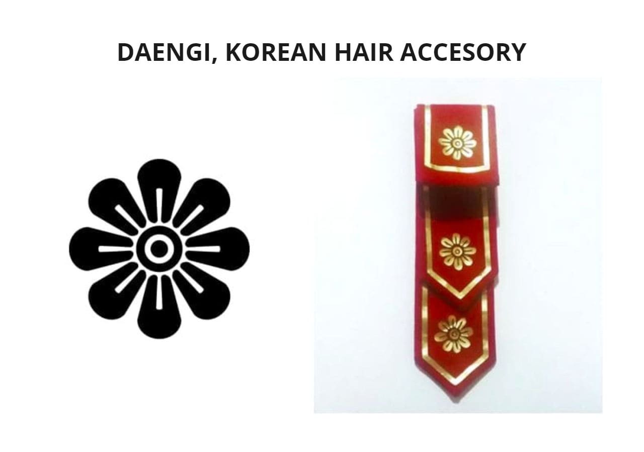
Daenggi, this hair accessory that single women used to wear in the Joseon era of Korea. I used gold vinyl to highlight the red tone of the design.
PARAMETRIC CONSTRUCTION KIT
I designed my parametric kit and I used Fab Lab’s laser cutting machine. I used MDF and acrylic among the main materials.
All the pieces were cut following the same steps that were done for the tests in the group assignment.
Next we will see the design and the assembly of the pieces:
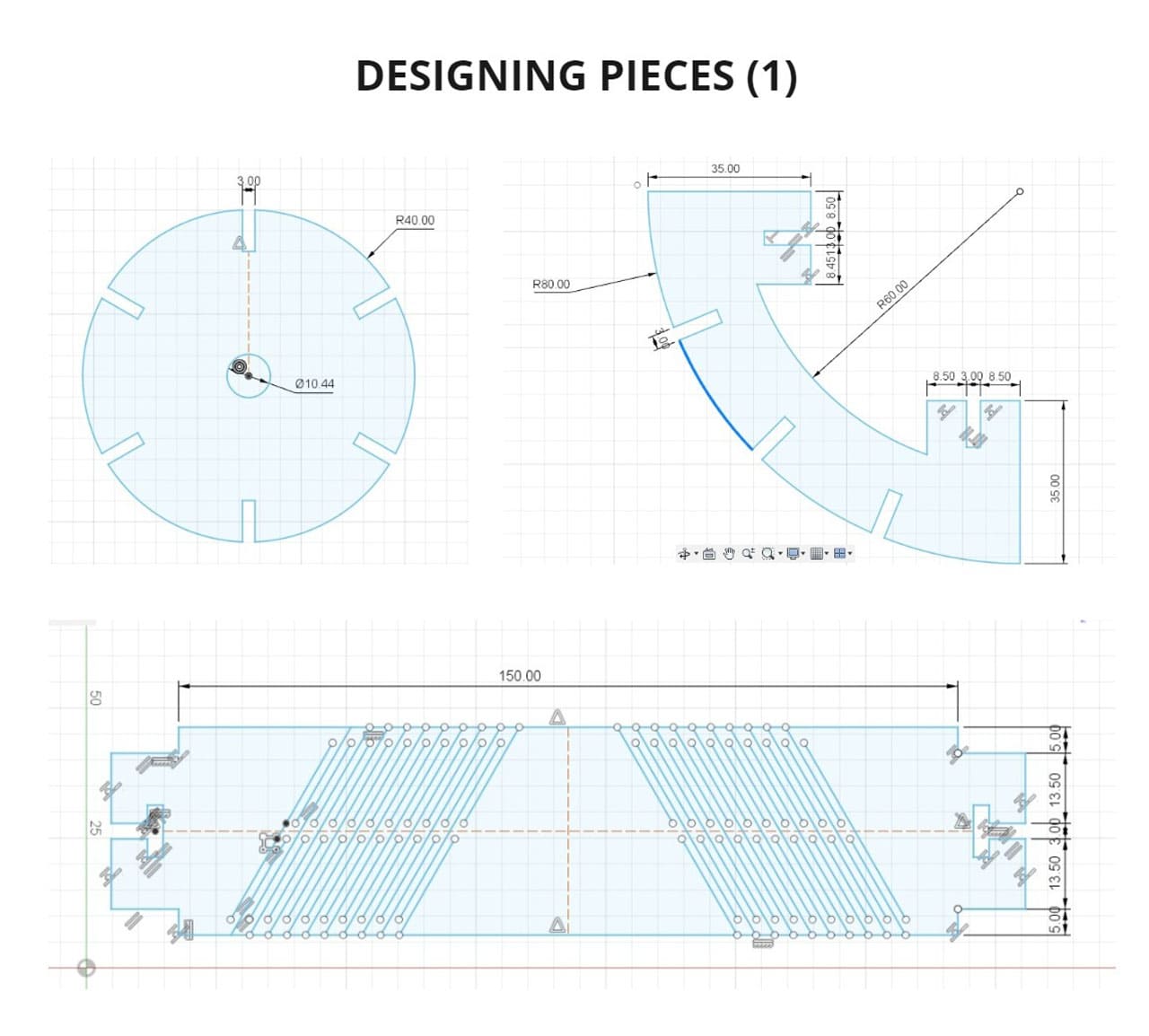
DESIGN
Make the design in Fusion 360, since it is a parametric program and then export the file to .DXF so you can use it with the laser cutting machine.
Points to consider for the design:
-
Nature is wise, complex figures are born from the repetition of basic geometry, like the Ice crystals that form a snowflake based on hexagons or the Flower of life, based on that we get proportions and angles that serve us to design in an easy and balanced way.
-
Taking into account that, use the following angles: 60°, 90° and 20°, as well as the design of different pieces, starting from the same base, with some changes but all in proportion.
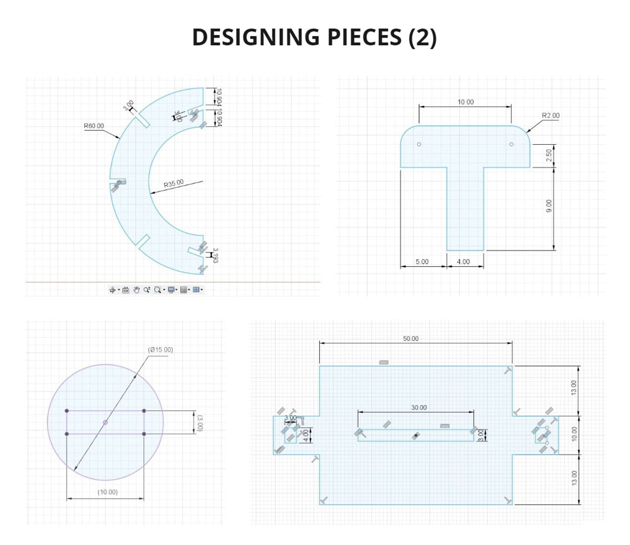
This is the individual result of each piece:
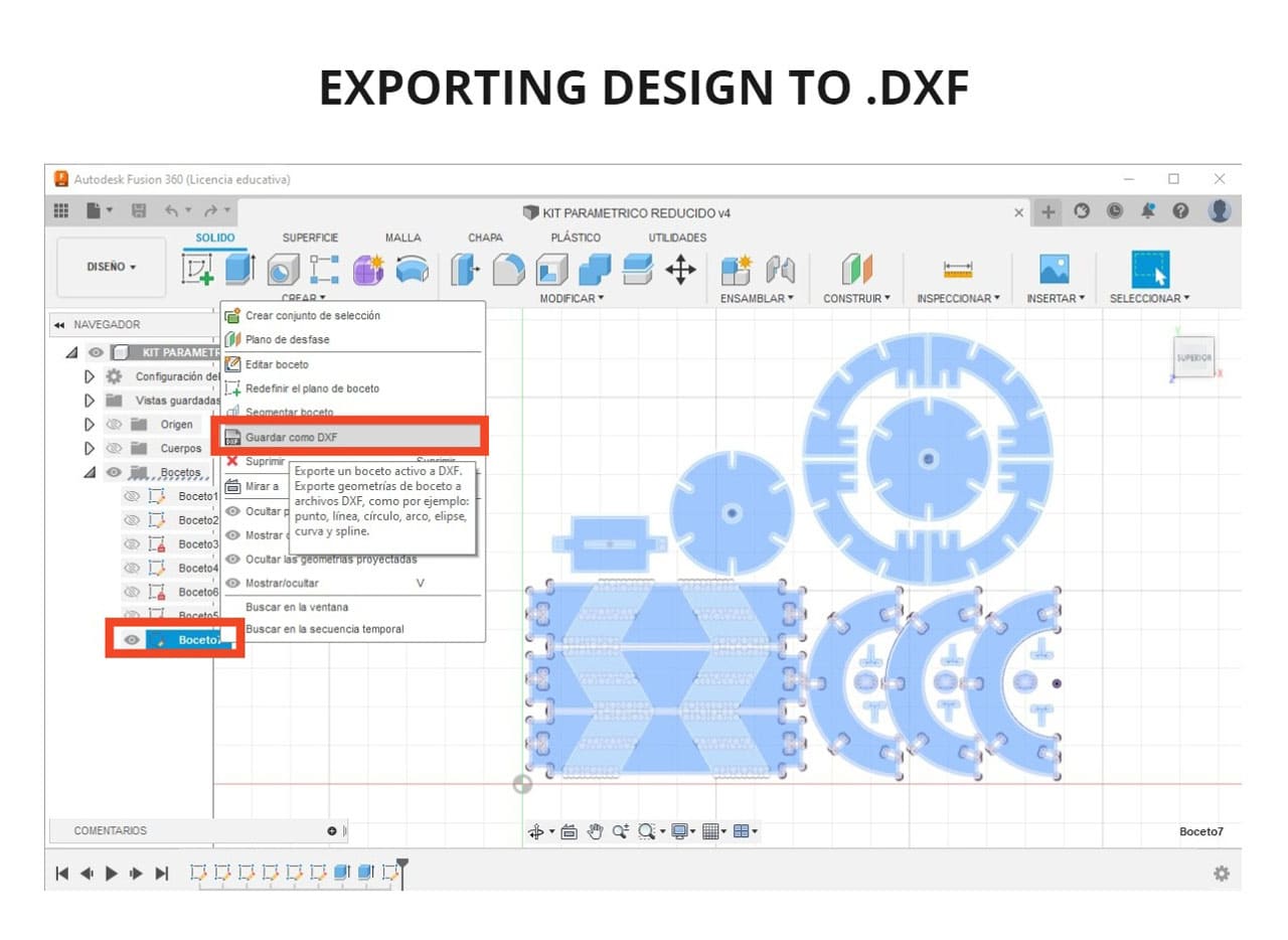
At this point I had not noticed that to export a sketch to .DXF, all parts must be on the same layer, so:
-
I extruded all the parts, selected the surface of one and clicked
CREATE SKETCH. -
Then click on
CREATE>PROJECT/INCLUDE>PROJECT. -
Select all the solids and click
OK.
Then everything would be in one layer, but certain lines that did not form a closed geometry were not going to extrude or project (the lines tilted at 60° inside the rectangle). So I had to redraw them on that layer.
The already projected lines cannot be moved, I tried several times, so I redrew them in that layer to be able to move the geometry before exporting it.
These are the pieces and I exported them from the BOCETO layer, right click and chose SAVE AS DXF.
This would be all to be able to export and be able to open it in any program and use it with the laser cutting machine.
When I got to this point, I realized that I forgot something very important, I placed 3mm of opening for the sockets but I had to place the right one according to the test in the group assignment. In this case the socket had to be scaled to 2.9mm and then sent to the laser cutting machine.
TESTING
For the cutting process, the same steps were performed as for the group assignment to prepare the machine and send the file.
Speed: 15mm/s
Power: 45.0%.

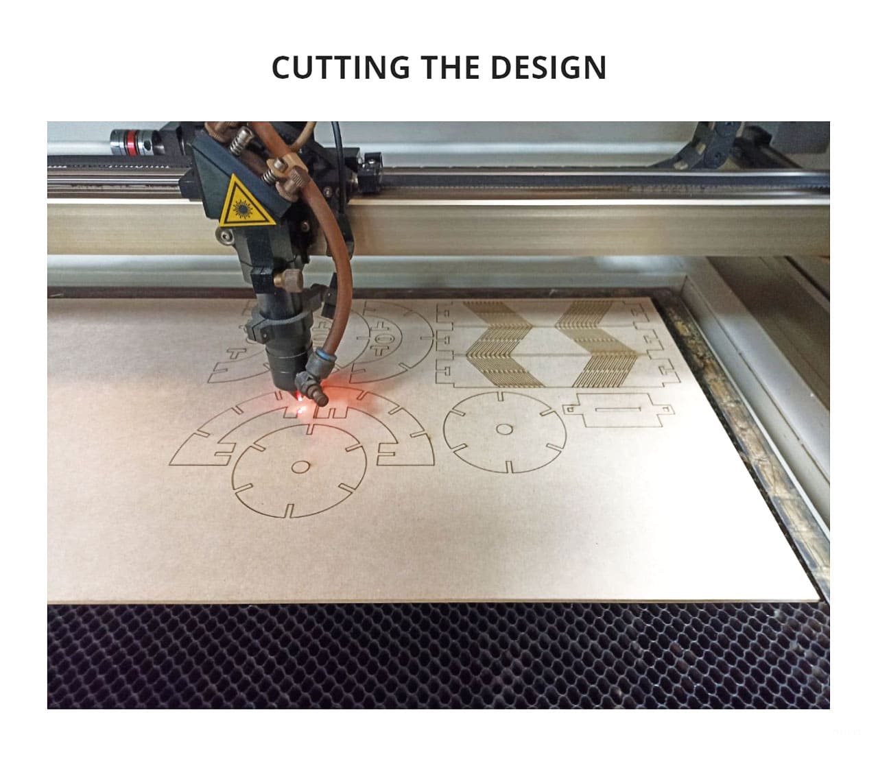
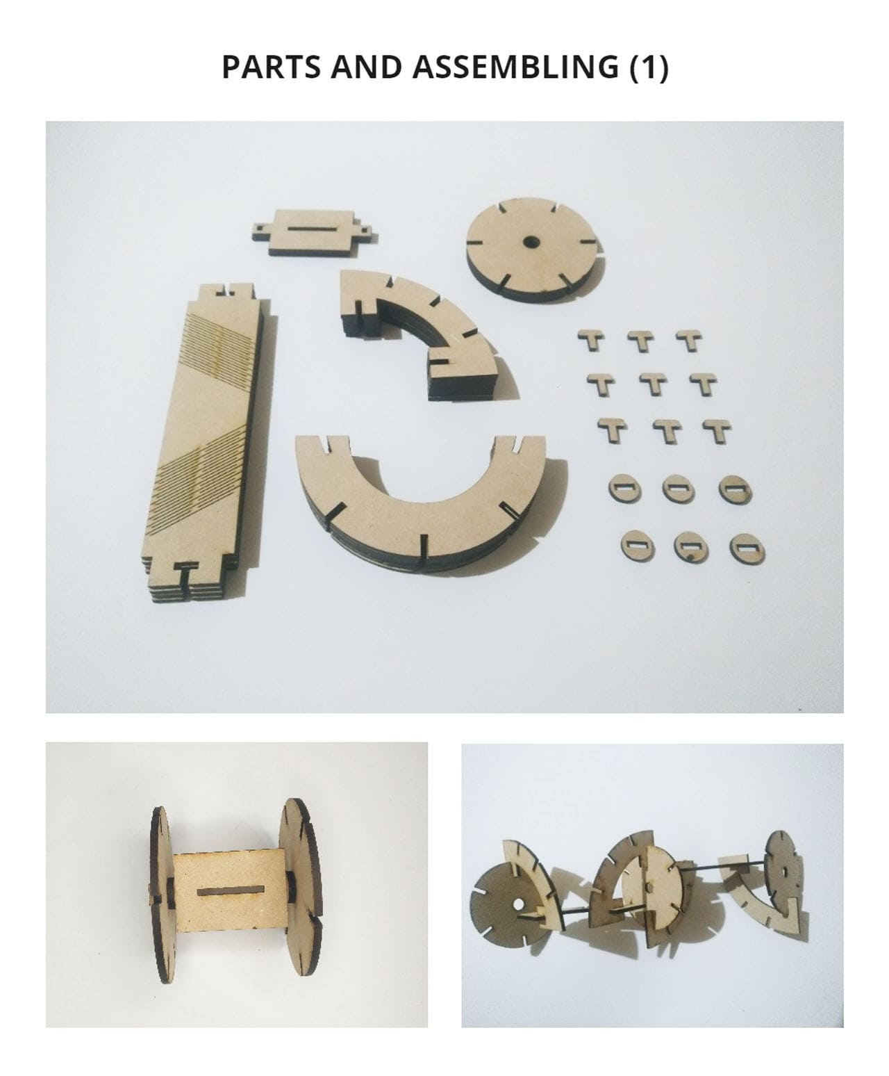
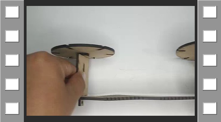
These are the cut pieces, they can be repeated multiple times and assembled in a modular way, I chose all these shapes so I could experiment with twists and folds.
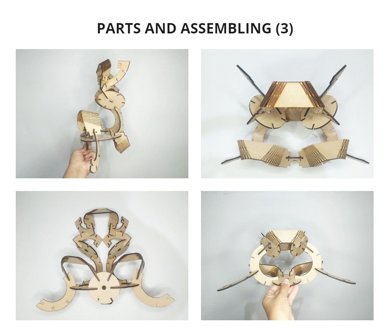
It was a lot of fun, I started with simple figures and then more complex structures with this kit. Before, I wasn’t interested in building figures with pieces, I wasn’t interested in legos either because I saw them as little bricks and I didn’t see curves or movements in the pieces because each piece is rigid.
On the other hand, merging movement, curves, angles and different directions in which the pieces go, creates many possibilities, from making something sculptural or imagining ships, places or characters. It’s very educational and fun, it stimulates creativity and you can assemble it however you want!
You can see it in the following photos as Parts an assembling:


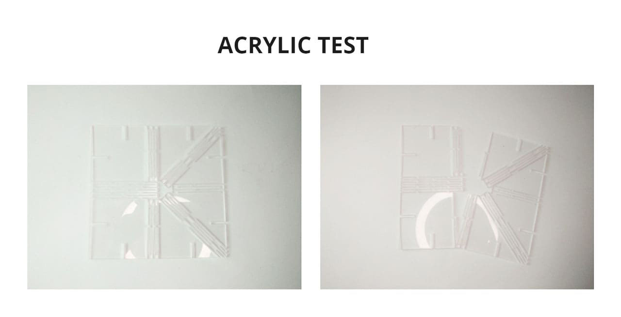
I also tried repeating a pattern using acrylic to see if it could be bent even more than in the group assignment tests, but it didn’t work, it broke 😅.
I will try to use other materials in the future with modular design and experiment. I really enjoyed this assignment and learned a lot in the process.
Always remember to enjoy the process and just do it!
VIDEO

3. CONCLUSIONS
-
Testing the material is very important to know the correct fittings and not to fail when we want to assemble something.
-
Cameo 4 it is a vinyl cutter very easy to use and very intuitive, you can also cut other materials and add a different accessory depending on what you are going to do, as you can also do engraving work with the foil quill.
-
When you make parts that are going to be assembled, you have to take into account the additional space that must be added, even if it is only a few millimeters, as it will make a difference.
-
If you want to export a sketch from Fusion 360 to .DXF, everything must be on a single layer.
-
It was great to design different shapes and to be able to experiment with them, to use rigid and curved pieces, to generate movement.
-
The shapes come from nature and if we use the proportions and play with it in our designs, we will achieve incredible things! I have been left with the desire to develop more designs.