5. Electronics production
1. GROUP ASSIGNMENT:
Characterize the design rules for your PCB production process.
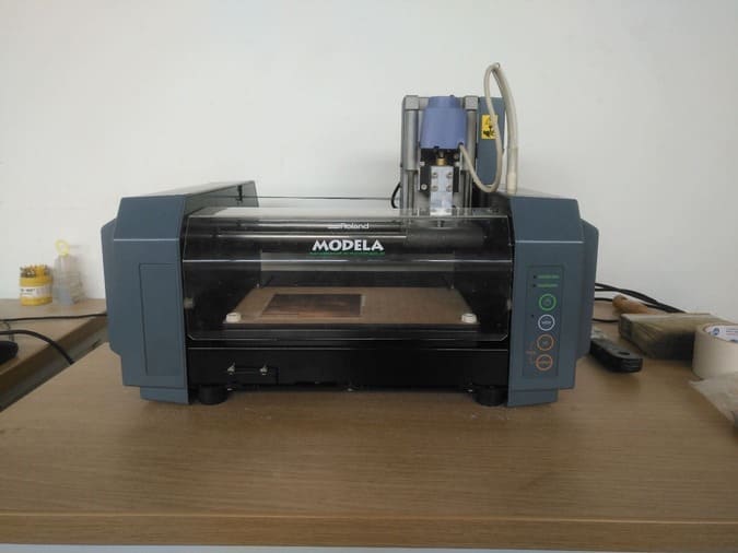
We started testing the milling machine available in the FabLAb ESAN, it is a Roland Modela MDX-20
This is a 3D milling capable machine with also a scanning function.
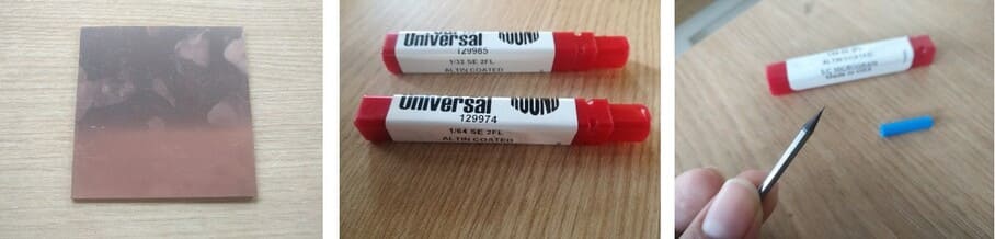
As milling material, we used a single-sided copper square plate of 100mm, and for the test templates, we used the files available here:
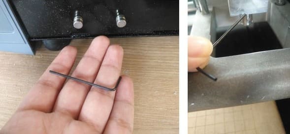
The milling bits available in the FabLab were one 1/64" (approx. 0.39mm) for the traces and a 1/32" (approx. 0.79mm) for the outline.
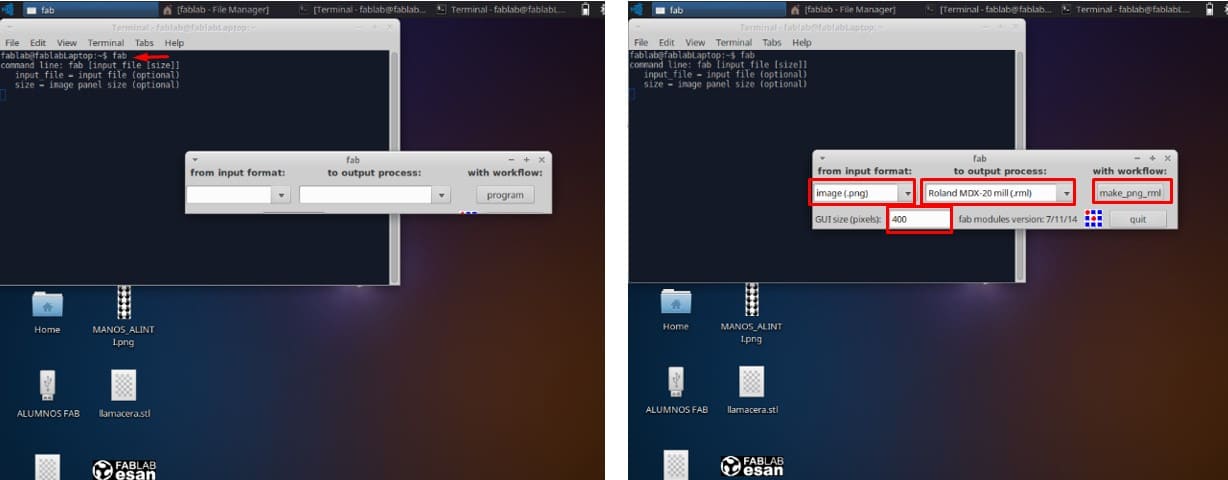
We need to convert the .png templates to a milling pattern so, we used the locally installed mods (for Linux) in the PC next to the milling machine.
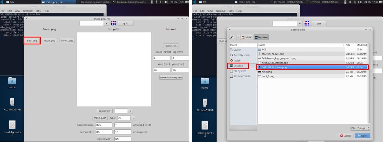
The steps are almost the same as the ones used for the vinyl cutting assignment, we first open the terminal and type sudo fab command to open the application. This opens a small window to select the input format (.png image), the output process (Roland MDX-20 mill (.rml)), and the workflow make_png_rml.
-
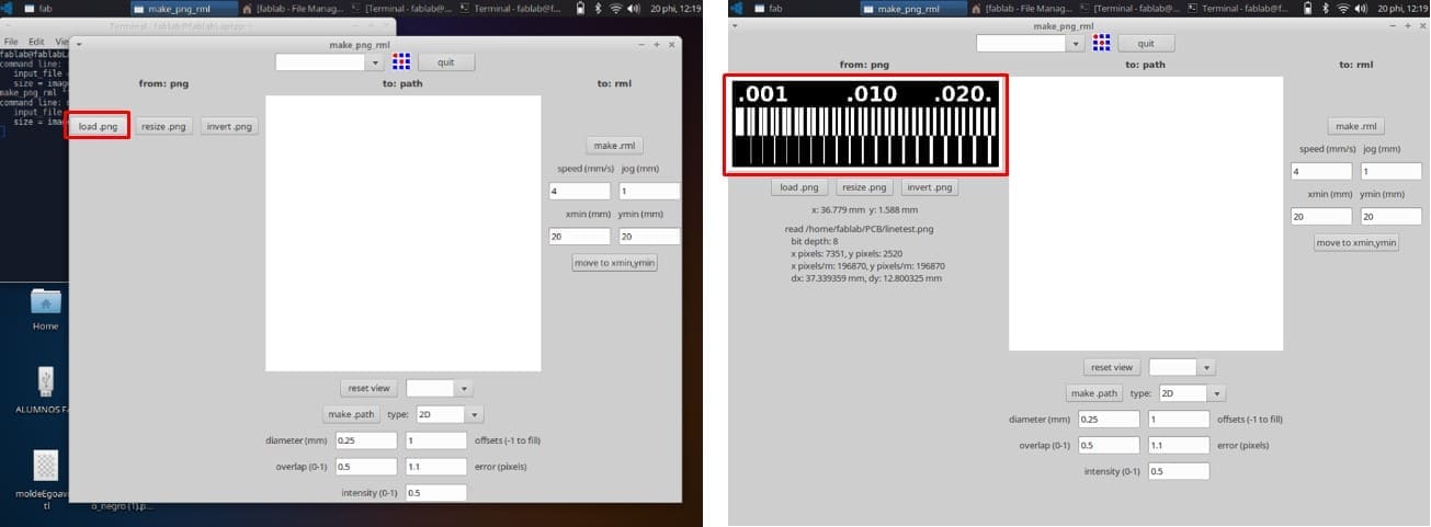
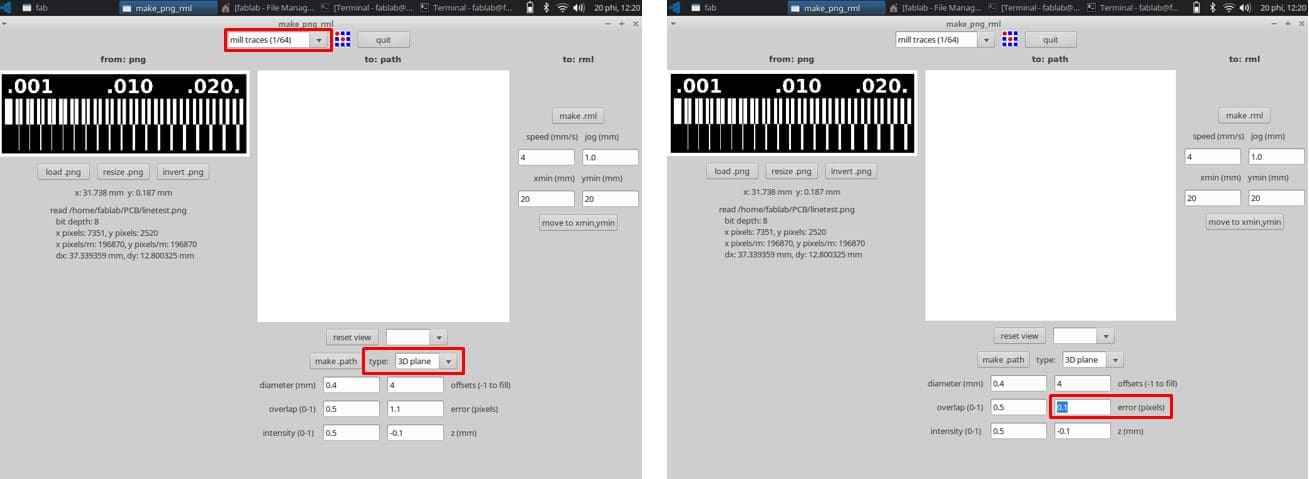
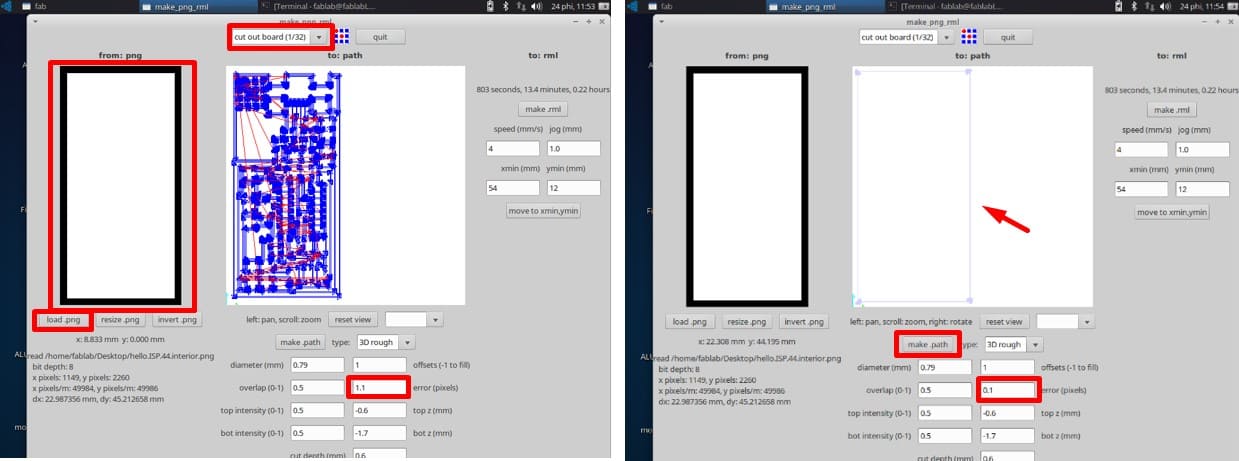
This opens the interface, load the .png image (first we select the milling traces file) and select the
mill traces (1/64)option from the top panel to indicate the process and the milling bit we’ll be using. -
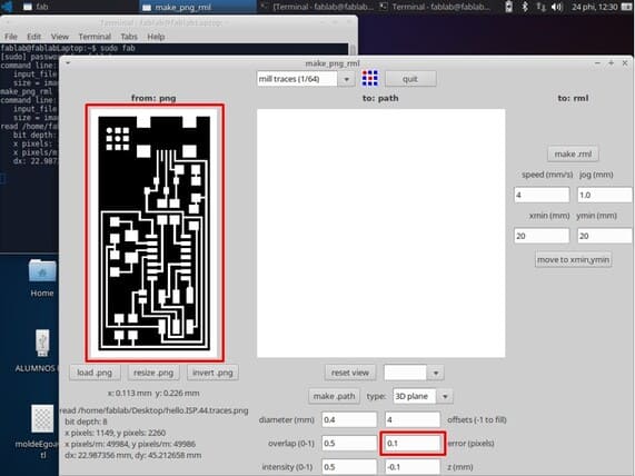
Then change the
error(pixels) value to 0.1 (it was set at 1.1 by default).Another very important factor is the X and Y coordinates, this would be set according to the position on the copper plate on the machine, this will set the starting point of the milling bit. -
We set this point to
20 / 20and use the move to“x” min, “y” minbutton to automatically place the bit into position. TheseX and Ynumbers need to be the same when using the outline file to cut the board! We used the default settings forspeed (4 mm/s), jog (1 mm), diameter, overlap, offsets, intensity, and Z as this is our first test run on the machine. Then, we hit the make.path button, this will generate the milling path of the tool.
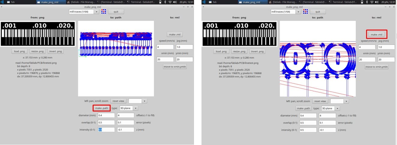
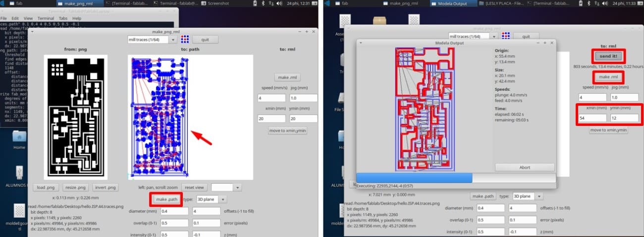
- Once we hit
make.path, the path is generated in the window next to the.png image, this works by recognizing the white parts of the image and then milling the outline 4 times, (this value is set by default to 4 offsets) but we can change it depending on the characteristics of the PCB design. The blue lines indicate the milling path, while the red lines indicate the traveling of the tool.
-
In the paths window, we can
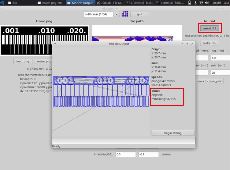
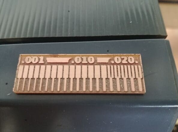
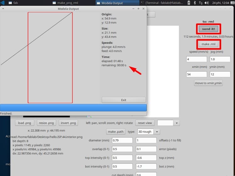
zoomin and inspect the design to prevent flaws that might occur while milling.For example, we noticed that for the traces the milling bit can only go inside the last five parts under the.020tag. After inspecting the paths we hit the make .rml button to generate the milling file and then click the send it! button to begin the milling work. This last action opens a new window called modela output where we can see the movement of the milling tool, this also gives an estimated time of milling. -
After inspecting the paths we hit the make
.rmlbutton to generate the milling file and then click the send it! button to begin the milling work. This last action opens a new window called modela output where we can see the movement of the milling tool, this also gives an estimated time of milling.
- We repeat the process for the outline file that will cut out or test from the copper plate, but this time we select the
cut out board (1/32)option on the top menu. Notice that this will vary the default settings, like offset is now set to 1, and there are new fields liketop Z, bot Z,and cut depth inmm. also, the intensity is separated in top and bot fields. The speed and jog parameters remain the same as with the traces.
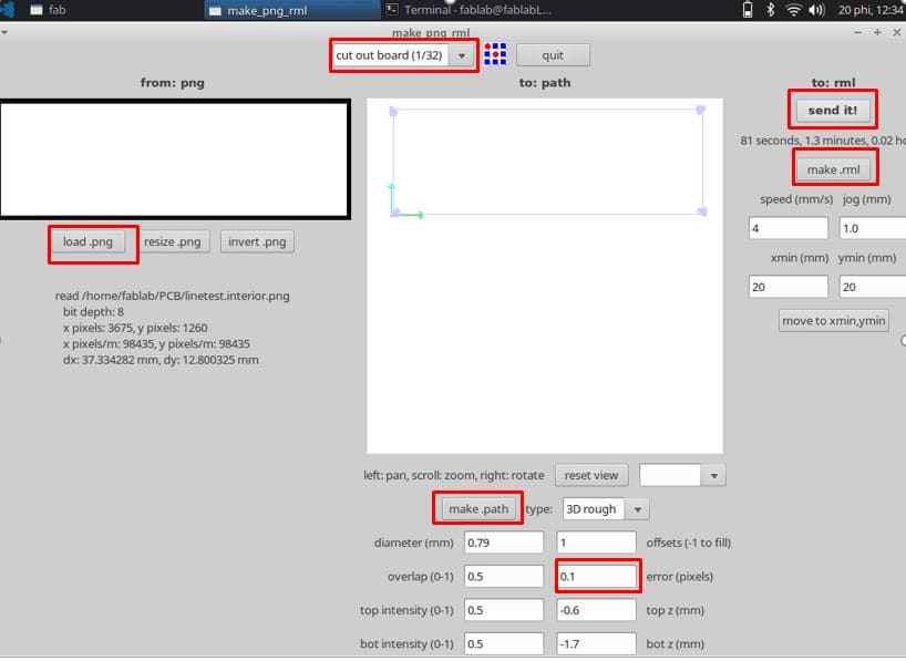
After we change the parameter of error (pixels) to 0.1 and double-check that the “X” and “Y” coordinates are the same we used in the previous file, we can press the make.rnl button and then It’s ready to send it to the milling machine!
Milling Machine configuration:
Before sending the file to the milling machine, we need to set up it.
-
“Turn on” / “Turn off”: For turn on or turn off the machine.
-
VIEW : for calibrating the
“x”, “y”axes. -
“UP” and “DOWN”, fo calibrate “Z” ax, these buttons are carefully used to mill or cut the material, If it doesn’t calibrate very well, the vibrations can move the material and cut badly the board.
IMPORTANT:
-
If the lid is removed from the machine, then the machine stops working.
-
Don’t allow the milling bits to fall, because the most thin tip is fragile, it can be broken.
-
Turn off the machine when you are going to make another configuration for milling or cutting.
-
We use a magnetic key to secure the milling.
HOW TO PLACE?
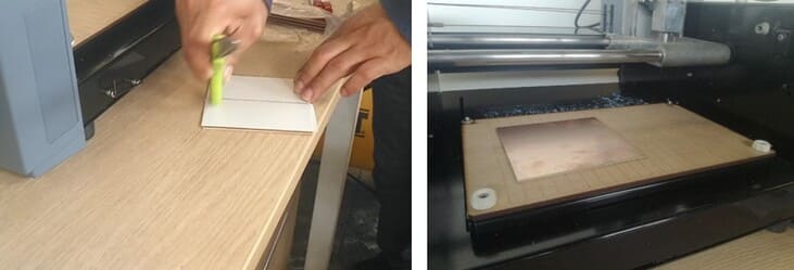
First, we use a double contact tape, stick it well to the plate and fixed it. Don’t leave spaces with bubbles, because if it is not well stuck, it can move when you are milling.
The base platform inside the machine is divided into 10x10mm squares, it helps us to better position the plate, for example, we can place in 10x10mm or 50x10mm, in this case, we use the first.
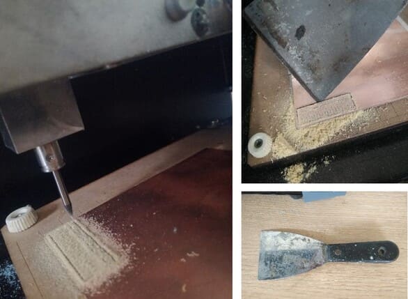
Second, put carefully half of the milling bits 1/64 into the milling machine and secure both sides (it has two screws). We make a teste and calibrate the material in “X”, “Y” and finally we use the button “DOWN” for the “Z” axis, If the material comes out as dust, it’s ready to use.
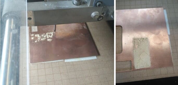
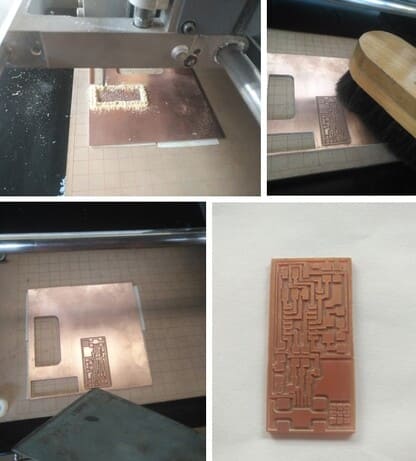
We send the setting up and the milling machine start to work, we get it!
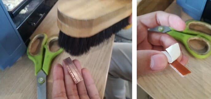
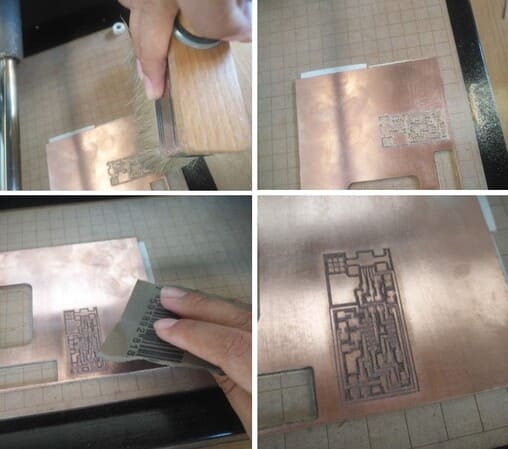
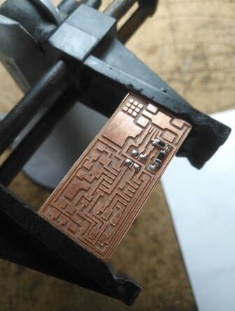
After the traces milling process ended we press the view button on the machine to inspect the finished piece, we carefully brush off the milling residue and noticed that the edges on the trace have a rough finish. Then clean with a squeegee, sanding and the finish will look much better.
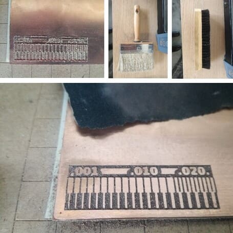
This is caused by using a cut-up milling bit that forces the copper traces to bent upwards. This was fixed by sanding (with fine grade sanding paper) only a couple passes are enough, this process is called deburring.
After the cut-out process ended we press the view option again to inspect the finished piece (milling bits 1/32), brush off the milling residue and separate the board from the plate with a paint scraper.
After peeling the double-sided tape, and cleaning we have our finished test board!
2. INDIVIDUAL ASSIGNMENT:
Make an in-circuit programmer by milling and stuffing the PCB, test it, then optionally try other PCB processes.
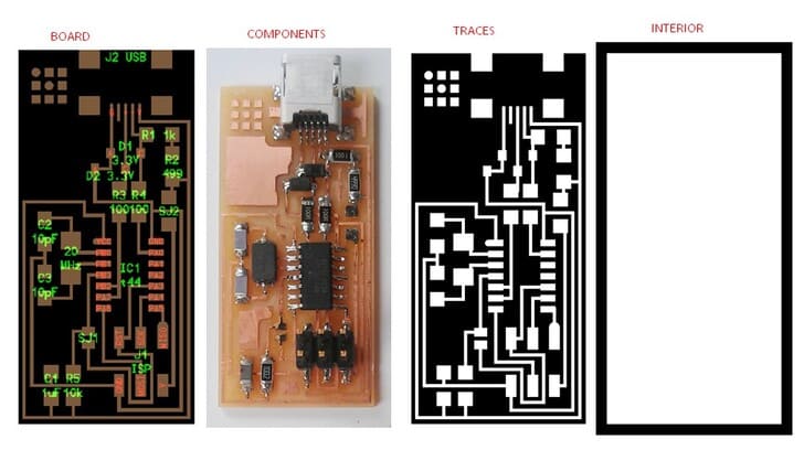
First, I chose one of the models given to us by the fab academy, I chose the ATtiny44 :
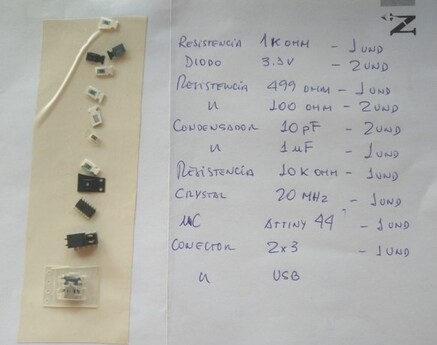
- Here I show the components I need to make my badge.
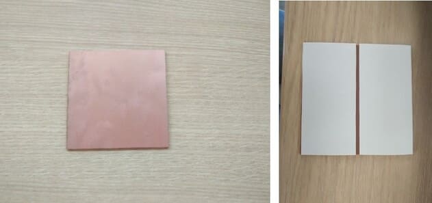
- This is the copper plate, I stick double contact tape all over the back and repeat the same steps done in the group work but with a different drawing.
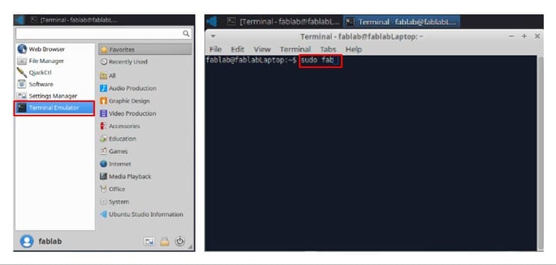
- Now, click on
Terminal Emulator, thensudo fab
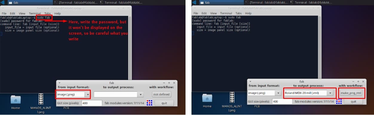
*Then place the password, then place the image we want in from input format and choose Roland MD-20 mill(.rml).
- Click on
load.png, go toDesktop, now click on the file you want to work on, I chosehello.ISP.44.traces.png
*This is the image I’m looking for, now to correct the error ,before it said 1.1, now 0.1.
*Now, click on make path, the image will start drawing strokes, now let’s do make.rml and finallysend it(Before changing the direction ofx , y` , as my drawing will be done on a plate where another design had already been drawn).
*It will start to trace our plate design, being as follows, previously we had to approach the drill to the plate and make a test.
*Now clean with a brush and use the sandpaper to leave the surface smooth.
*For cut the border, then change to cut out board(1/32), upload the image to load.png, correct the error from 1.1 to 0.1, then click on make.path and the layout will appear on the screen.
*Click on make.rml and send it.
*After cutting the edge, remove with a spatula, sand and clean.
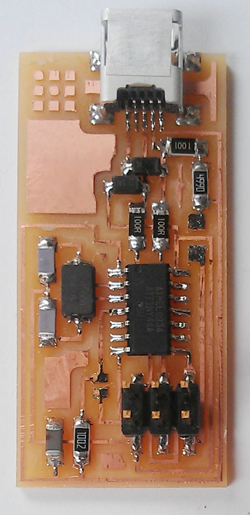
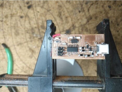
*It’s time to weld the elements together!
I melt the copper wire with an electric soldering iron to put all the parts in place.
Everything was going well, until I tried to record and couldn’t, What happened?
There was a part that had no connection, so I had to join it, how? I used a piece of wire and stripped both ends, joined them to the area with copper and used the multimeter to check if there was continuity or not, it was ready!
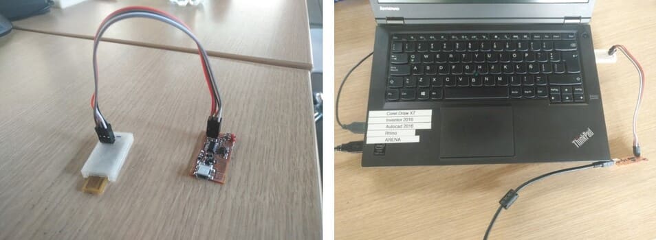
*It’s time to record! Get a programming device, then connect the wires in the same position of the colors and connect it to the computer.
*Finally, we start recording with the following commands:
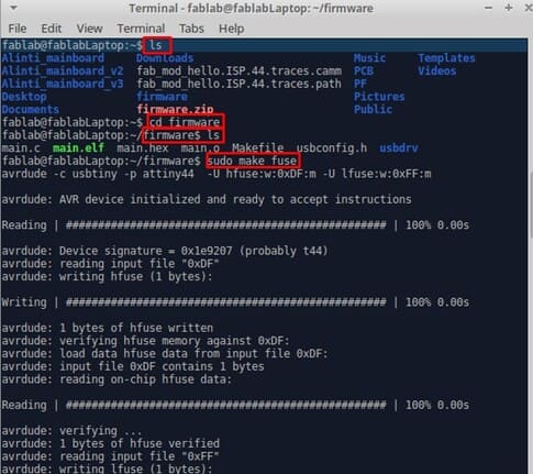
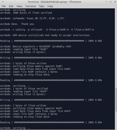
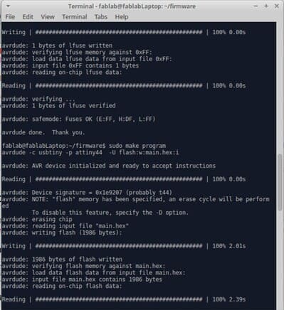
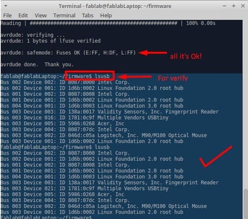
When you see the message: Fuses ok , it means that it is already configured, you can verify it by typing firmware$ lsusb.
That’s it, your board has been programmed.
Conclusions
It is better to use Linux for programming and in case you do not want to damage the operating system, you can use a Raspberry Pi, as a mini computer to be able to program without fear.