13. Input devices
Group assignment:
-
Probe an input device(s)’s analog and digital signals.
-
Document your work to the group work page and reflect on your individual page what you learned.
Individual assignment:
- Measure something: add a sensor to a microcontroller board that you have designed and read it.
1. INDIVIDUAL ASSIGNMENT
This week I had to add an input device and I chose to use an Endstop Limit Switch that I will use in my final project.
DESIGN
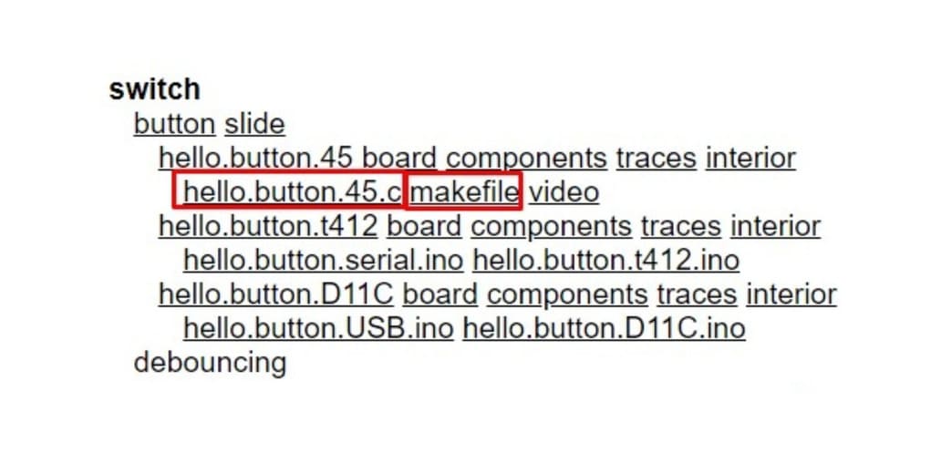
I used Neil’s model as an example, called SWITCH, hello.button.45, you can see it below:
In my case I chose a sensor that I bought from a local supplier because that model was different from others that we have in our node and is obviously different from Neil’s example, it is also called Micro Switch or Snap-action Switch.
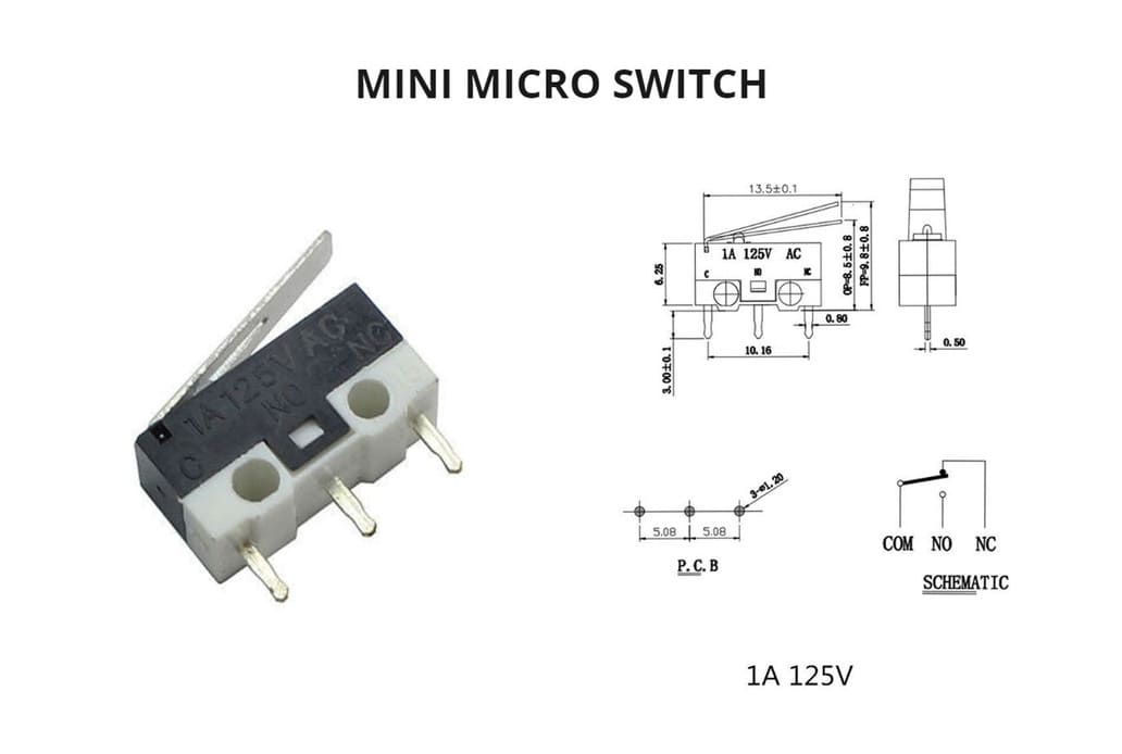
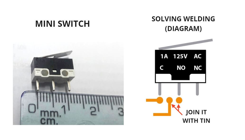
This is a basic guide about this type of sensor: Micro switch - Guide, but that’s not enough, I was looking for the datasheet of the model I have and this is what I found:
-
MICRO SWITCH-KW10 SERIES: Very similar to KW10-Z2P Long lever
Thanks to this, I obtained the main data:
This is a sensor that detects the position of a moving element by mechanical actuation.
Features
-
Model: Limit switch
-
Type of swith: SPDT
-
States: Normally open(NO) and normally closed(NC)
-
Max. Voltage: 125 V
-
Max. current: 1 A
-
Contact resistance: 30MΩ max
-
Operating temperature: -25 ° C to + 65 ° C
-
Dimensions 12.7 x 5.8 x 6.5 mm
-
Lever : 13.5 mm length
You can see more details in the following image:
You will also need the library that has the component for EAGLE, because this sensor was not in the FAB library. I searched and found this one that will be very helpful:
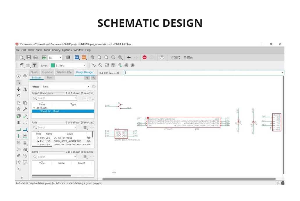
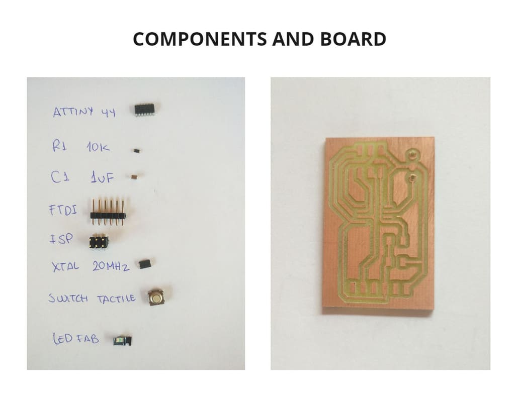
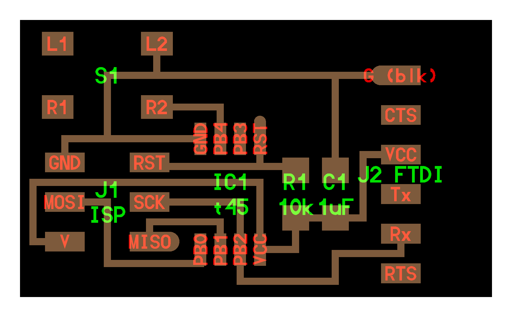
I developed my schematic design making the connections, indicating name and value to the components as in Electronic Design week but with different components.
I was adding the components and joining as in the Electronic design week, these are the components I used:
UC_ATTINY45-SI
R1206FAB : R1 - 10K
CAP_UNPOLARIZEDFAB : C1 - 1 uF
CONN_06_FTDI-SMD-HEADER
CONN_03x2_AVRISPSMD
SWITCH-SPDT-PTH-11.6X4.0MM-LOCK
This is the schematic design that I made:
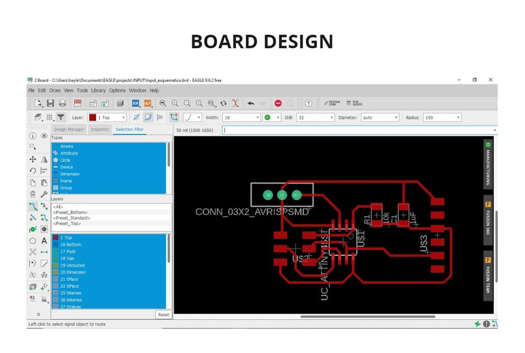
Then I started to make the board design and trace the components with the ROUTE AIRWIRE tool. I then applied DESIGN RULES and everything was well connected.
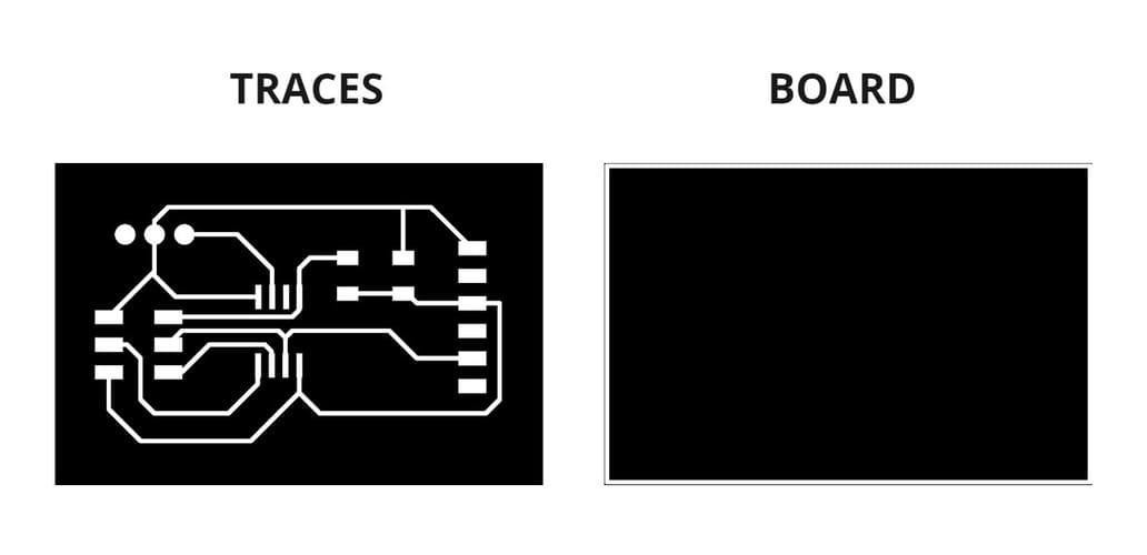
Finally, I drew the borders and then deactivated the layers to export separately the traces and the border of the board. I followed the same process I did in the electronic design assignment, you can review it in the following link: Electronic design week
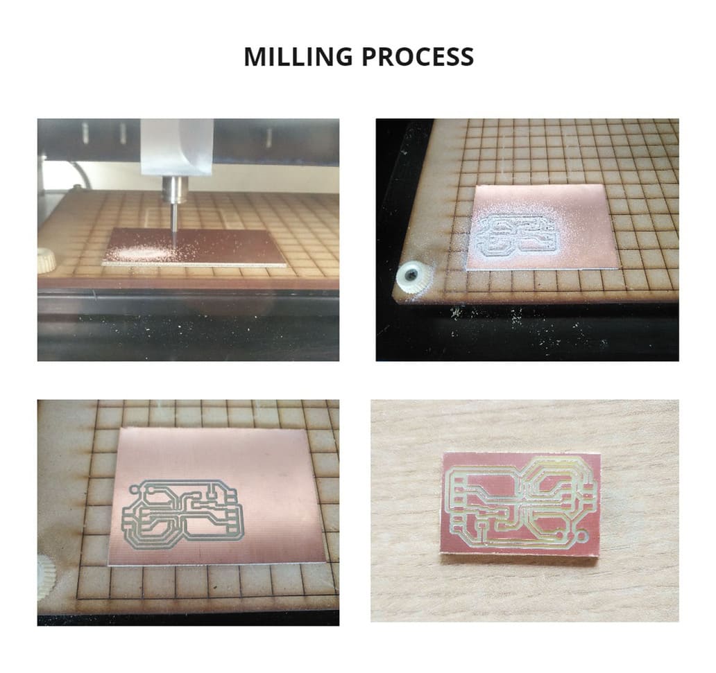
FABRICATION
For fabrication I followed the same steps for using the Roland Modela MDX-20 milling machine on Electronic production’s week. The milling cutters used are the same, 1/64'' and 1/32'', as well as cutting and milling configurations.
You can see it in the following link: Milling Machine configuration
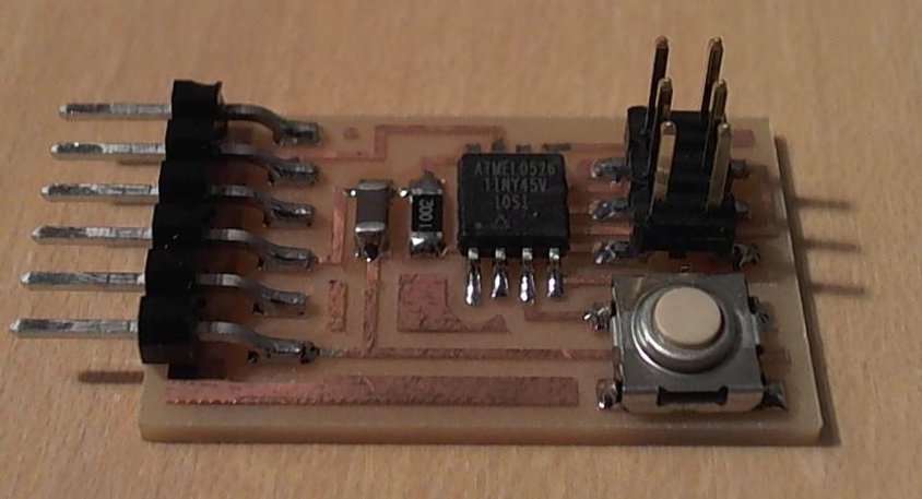
SOLDERING COMPONENTS
One thing I have to confess is that I made the design in Eagle and fabricated the board before buying the sensor, it turns out that I didn’t use the right component from the library to make the design.
In the initial part I left you the technical data sheet of this sensor, according to that, there is still a solution for this problem.
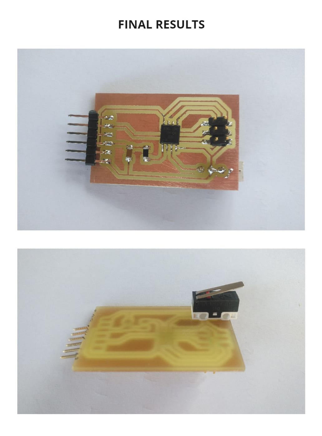
First, to solder this switch we only need to use 2 of its legs and the component was very large for the space available, I chose to use the COMMON (C) and NORMALLY OPEN (NO) because those are the ones I need so that when the sensor is pressed, the mechanism stops.
Then I drilled two holes in the board (because the sensor had legs that went through the board), these are to be connected to C and NO. I used tin to bond the connection to NO, as it was not bonded as it should be due to the size of the sensor exceeding the design.
The sensor is on the reverse side of the board, so that there will be no problems with other components when it is pushed.
PROGRAMMING
For programming I downloaded the files hello.button.45.c and makefile that belonged to the Switch with Attiny 45
I saved both files in one folder and renamed the file hello.button.45.make to Makefile, as in the Devices assignment
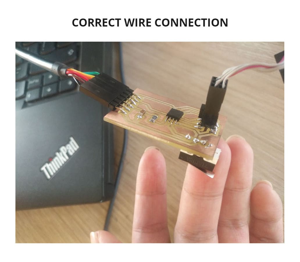
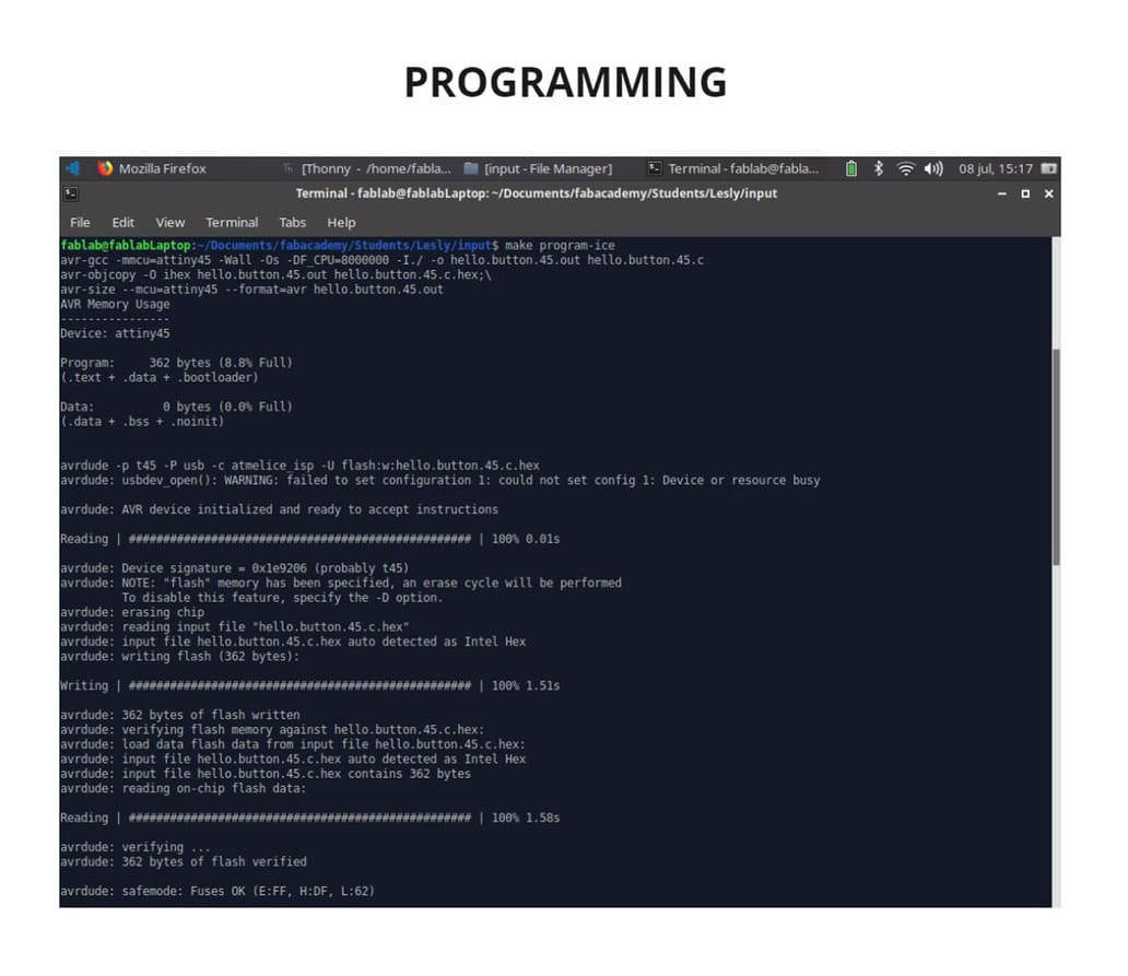
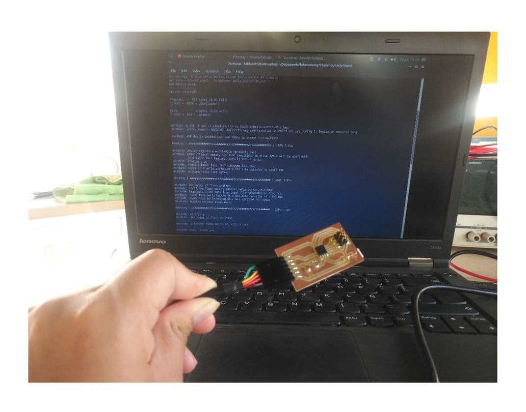
I connected the FTDI and ISP to the computer and the programmer respectively, then I entered the LINUX TERMINAL, entered the folder where the Makefile and hello.button.45.c files were and wrote the make program-ice code.
The programming was successful because at the end I got the message FUSES OK.
TESTING
To see that the sensor was working, I disconnected the programmer and just left the FTDI input connected to the computer.
I used the Arduino Serial Monitor so that I could confirm the signals it sent each time the switch was pushed.
You will see more details in the group assignment because I used my board there for the digital signals example: SENSOR SWITCH TESTING
2. GROUP ASSIGNMENT
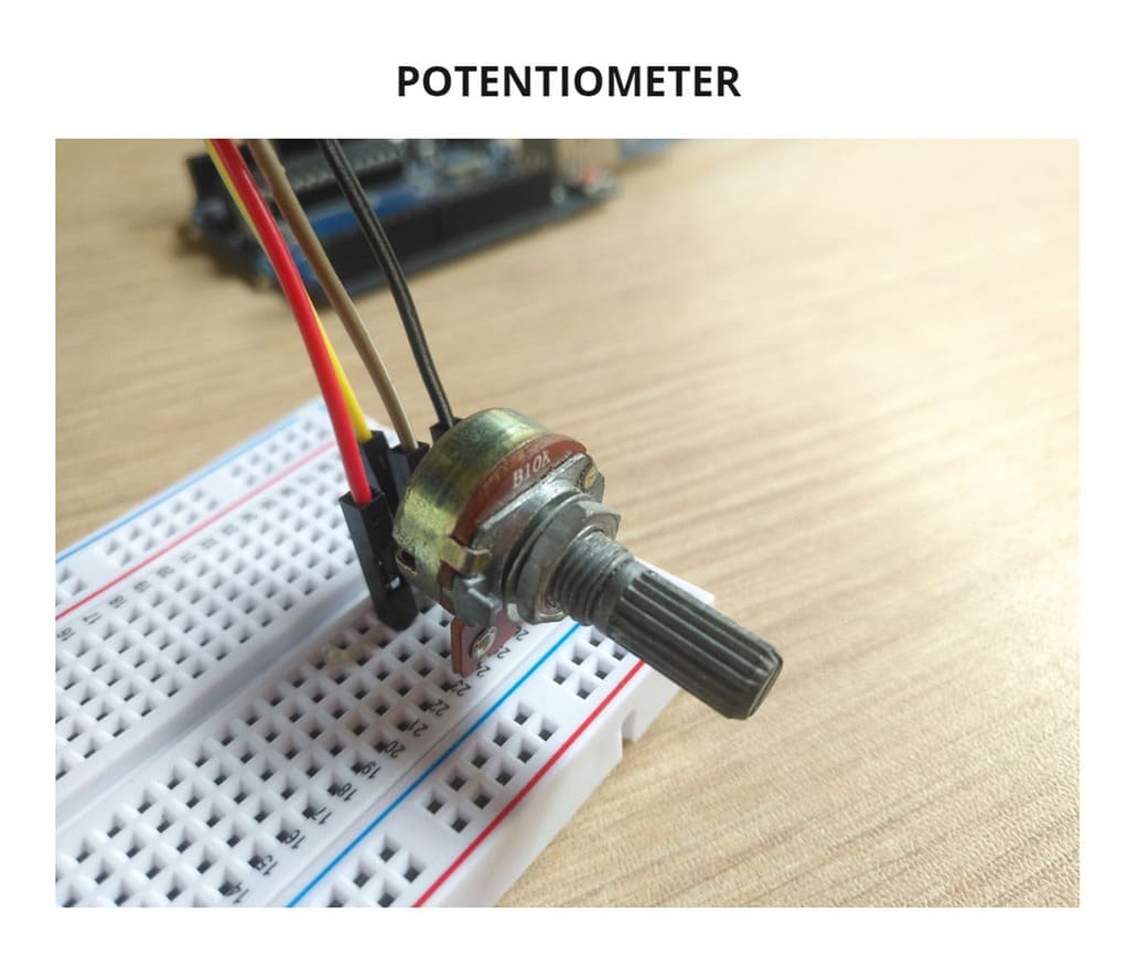
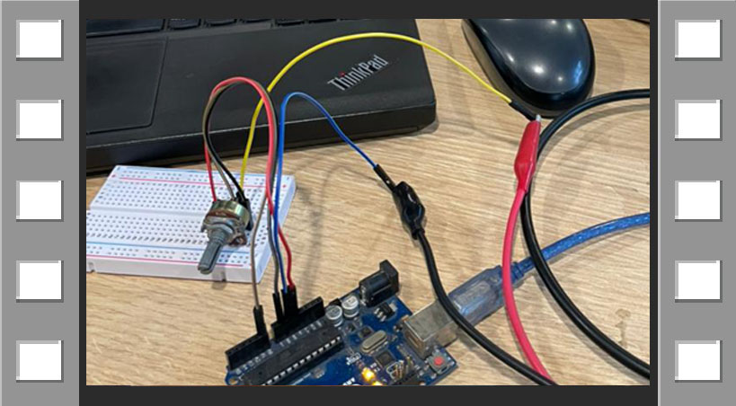
For this assignment I used my individual assignment board to test that it works and sends digital signals, I also used a potentiometer to test the analog signals.
DIGITAL SIGNALS
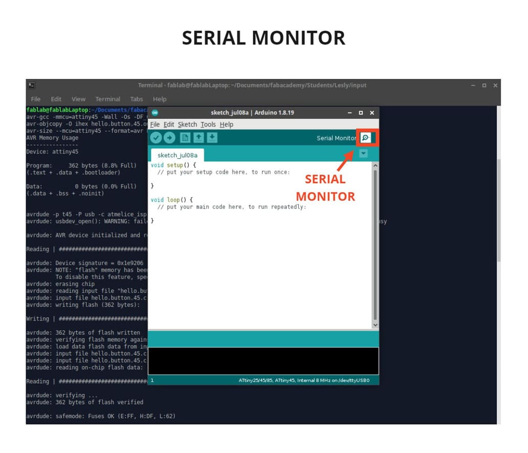
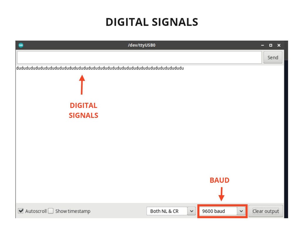
Only the FTDI of the board was connected to the computer, what I did was to enter ARDUINO IDE and click on the SERIAL MONITOR.
A new window opened in which I had to choose 9600 BAUD in order to display the signals. Finally I pressed the sensor lever and every time I did it, the syllable du appeared on the screen.
The programming was successful and was demonstrated with the digital signals!
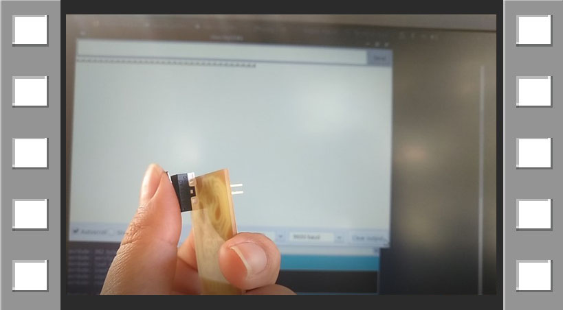
You can see the photos and video below to see the detail of each step:
VIDEO

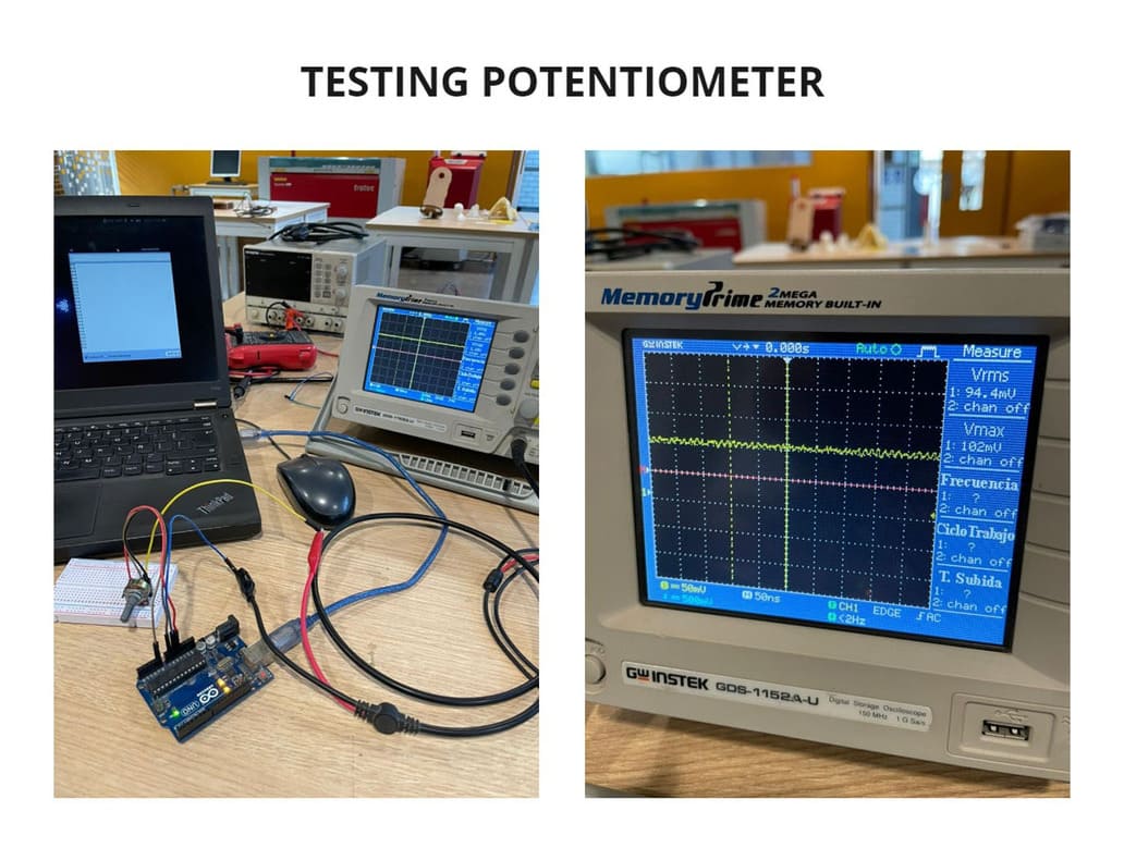
ANALOG SIGNALS
To measure the analog signals, I used the Oscilloscope, an arduino board and a potentiometer.
I connected everything, including the arduino board to the computer, then entered the ARDUINO IDE program and clicked SERIAL MONITOR.
Every time I turned the potentiometer, the values changed on the serial monitor, just like on the oscilloscope, the signal went up and down, as well as the voltage.
On the oscilloscope the signal was almost a straight line, it had very small noises throughout the signal.
It was very interesting because we can see the behavior of this type of signals numerically as well as graphically, detecting if there is any anomaly.
You can see every detail in the following photos and video:
VIDEO

3. CONCLUSIONS
-
Before designing in an IDE software, you should have the physical component you are going to use, so you can measure and know the area you need inside your board.
-
The Arduino serial monitor is very efficient to visualize analog or digital signals.
-
The oscilloscope is very useful to see the behavior of the signals, you should learn to handle it at least basically because it will be necessary for many projects.
-
The BAUD measurement varies according to the device and components used, for Arduino is used 9600 baud.