6. 3D Scanning and printing
Group assignment:
-
Test the design rules for your 3D printer(s).
-
Document your work and explain what are the limits of your printer(s) (in a group or individually).
-
Document your work to the group work page and reflect on your individual page what you learned.
Individual assignment:
-
Design and 3D print an object (small, few cm3, limited by printer time) that could not be easily made subtractively.
-
3D scan an object, try to prepare it for printing (and optionally print it).
1. GROUP ASSIGNMENT:
In Fab Lab Esan we have the following 3d printing machines:
FDM 3D PRINTER:
Specialized 3D printers and production thermoplastics to manufacture strong, durable and dimensionally stable parts with higher accuracy and repeatability than any other 3D printing technology. At Fab Lab Esan we have the following:
SLA 3D PRINTER:
Optical fabrication is an additive manufacturing process that uses resin that cures by ultraviolet light in a tank, and an ultraviolet laser to build the objects. At Fab Lab Esan we have the following:
We will test them and see the difference.
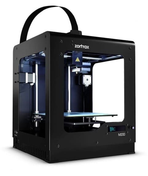
ZORTRAX M200
It is a professional 3D printer oriented to sectors such as architecture, engineering, medicine and industrial design, which integrates:
-
Build volume: 200x200x185mm
-
Weight: 13 kg
-
Calibration system: Automatic
-
Materials: Serie Z-Filaments.
-
Extruder: One extruder.
-
Nozzle diameter: 0.4 mm
-
Connectivity: SD card, wifi.
-
Double layer of Raft
-
Slicing Software for 3D Printer: Z-SUITE
TESTING
We will use the following file for the final calibration test.
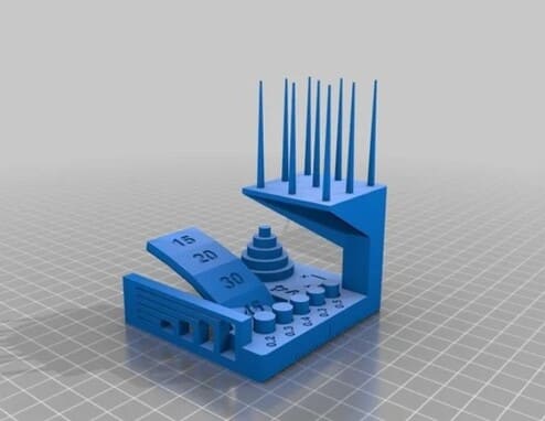
1.Download the Thingverse file.
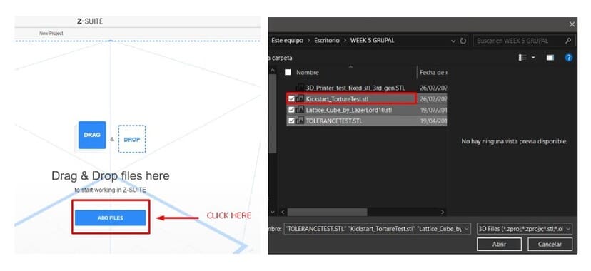
2.We are going to open Z SUITE, which is the program we use with this 3d printer.
3.Click to ADD FILES and open the file in .stl , the name of this file is Kickstart_TortureTest.stl.
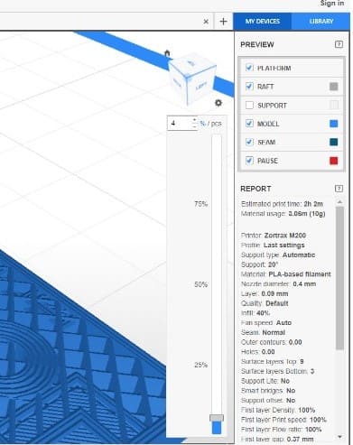
4.Once the file is opened, you can view the parameters and modify them, such as material type, thickness, temperature, speed and more.
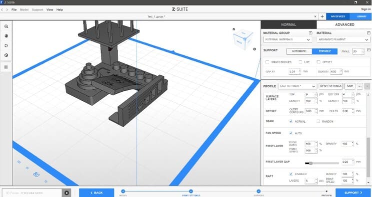
5.In this case we will use Raft, so that the piece has a good base and there are no problems printing (an error from the beginning, can cause the whole piece to go wrong).
But we will not use supports, since we are testing how it prints without them and if there is any deformation or anomaly in the finishes, according to inclination or thickness.
You will also be able to visualize the printing time or see the filling and modify it.
The parameters I used:
-
Material: PLA- based filament
-
Infill: 40%
-
Platform: Enabled
-
Raft: Enabled
-
Support: Disabled
The total time for printing was 10h 8min. In order to visualize how the filling would look like, there is a bar that indicates the percentage of the volume, you can raise or lower it to see the inside filling.
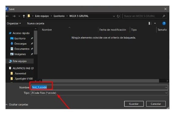
6.You are going to save your file and the format is .ZCODE , you must save the file in the usb memory to be able to place it in the 3d printer.
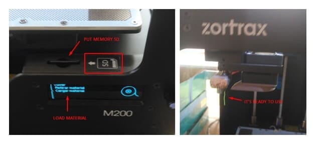
7.Then, prepare the 3d printer for proper handling and good results, verify the temperature of the bed and load the correct material, in this case PLA, follow the instructions below:
-
First, turn on the machine.
-
Put the SD Memory.
-
Load the filament.
-
Go to the option
MAINTENANCE>MATERIAL>LOAD MATERIALand wait for the material to warm up and that the material starts to come out, then it’s ready to print.
8.The SD memory has already been set in the previous step, now we are going to send the file to print:
-
MODELS>PRINT:TEST_1.ZCODE. -
Then the platform will start to heat up.
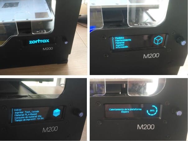
9.When the platform reaches 100% heat, it starts printing.
Once the printing is finished, wait a minute and remove it with an spatula and take off the base.
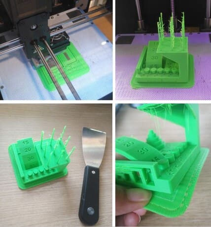
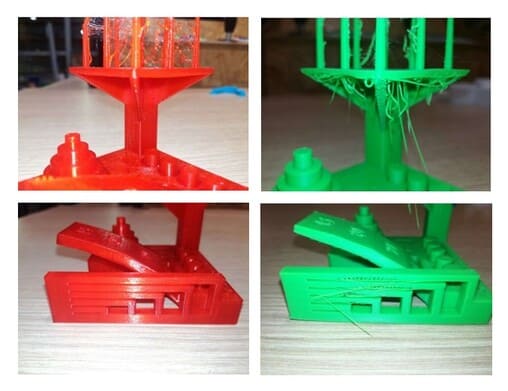
CONCLUSIONS
-
Horizontal distance: In the first photo we can see that the greater the distance between horizontal volumes without support, the greater the deformity, the material starts to come out like threads.
-
Tolerance test: Some pieces come out easily, while others have more difficulty and get stuck, this helps to know the necessary space we need to fit a piece with another.
-
The inclination of a volume is important, as we can see, without supports, the volume leaves a rougher and rougher finish.
-
In the final photo you can see that the material is dripping and are in the form of threads hanging, this is the result we get if you print something without supports completely horizontally.
-
In the final part of the test, we tried to see up to what thickness can be printed well, in this case, the thinner it was, the more deformity it showed, the material began to resemble a spider web.
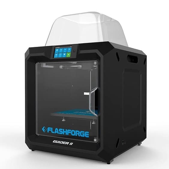
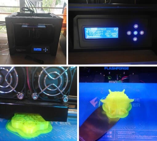
FLASHFORGE GUIDER II
The Flashforge Guider II is an industrial-grade 3D printer designed for the extreme hobbyist or prosumer. designed to provide the maximum stability and quality when printing your designs.
-
Build volume: 280x250x300mm.
-
Weight: 30kg
-
Calibration system: Automatic
-
Materials: ABS, PLA, PETG, Color-change, as well as flexible TPU and TPE.
-
Extruder: One extruder.
-
Nozzle diameter: 0.4 mm
-
Connectivity: USB, WiFi, Ethernet, Could Printing, FlashCloud, PolarCloud
-
Raft: The minimum raft thickness and the default value is 0.5mm
-
Slicing Software for 3D Printer: FLASHPRINT
TESTING
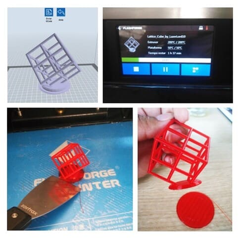
We will the same model that we used in the previous 3d printer, with this we can compare and see the differences in finishing and printing.
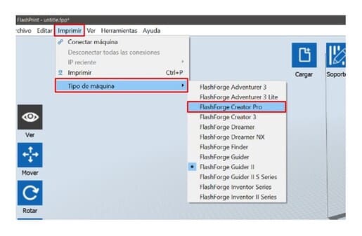
1.We are going to open FLASHPRINT, which is the program we use with this 3d printer.
2.Click on PRINT and choose the MACHINE TYPE, in this case, the FLASHFORGE GUIDER II.
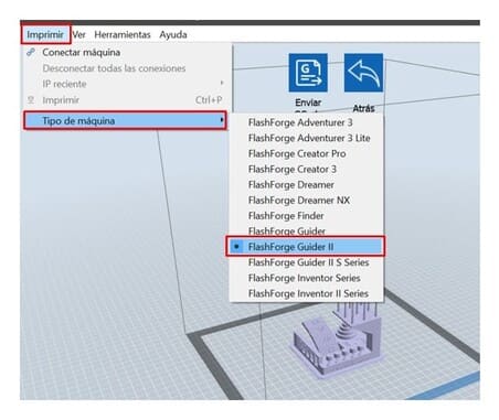
3.We can configure small things like removing the supports and print the raft, click on PRINT, it will be saved with .GX termination, be careful, it must be configured with the material that will print, in this case, PLA.
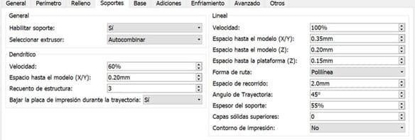
The parameters I used:
-
Material: PLA
-
Thickness: 1.75 mm
-
Extruder temperature: 200°C
-
Platform temperature: 50°C
-
Infill: 15%
-
Filling pattern: Hexagon
-
Raft: Enabled
-
Support: Disabled
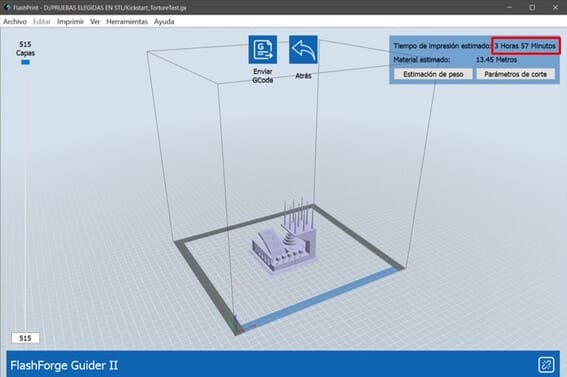
4.The print time estimate will come out when the file is saved, in this case is 3 hours and 57 minutes.
5.Then, we are going to save the file on a USB and connect it to the machine:
-
First, turn on the machine
-
Load the material (PLA)
-
Put the USB
-
Before printing, apply adhesive on the printing bed.
-
On the touch screen select
PRINT, then click on our file , in this caseKickstart_TortureTest -
The machine will start heating and finally printing.
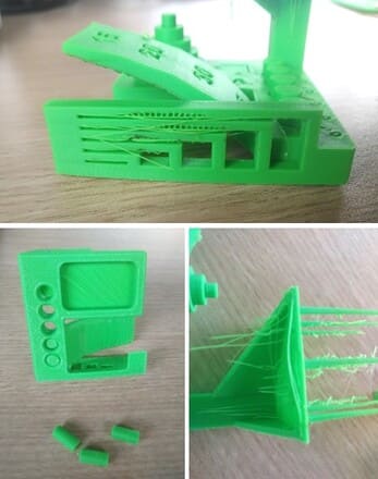
6.Gently remove the printed object with a spatula, also remove the raft, this is the result:
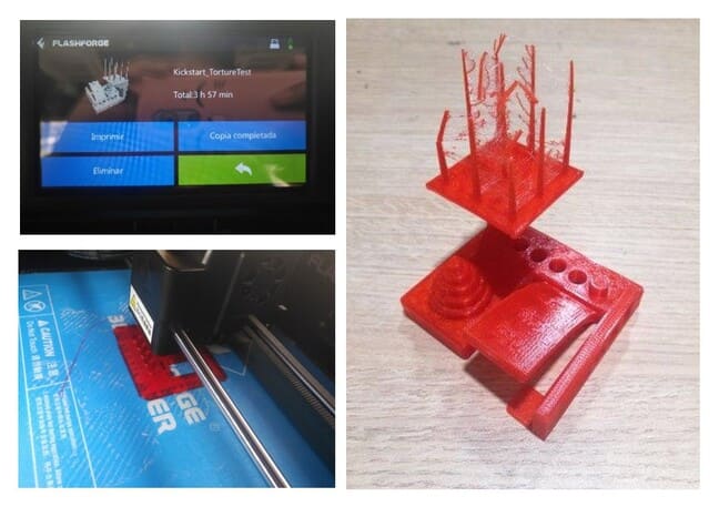
CONCLUSIONS
-
Horizontal distance: There is not much noticeable deformation, not even hanging threads of material.
-
Tolerance test: Some pieces come out easily, while others have more difficulty and get stuck, this helps to know the necessary space we need to fit a piece with another.
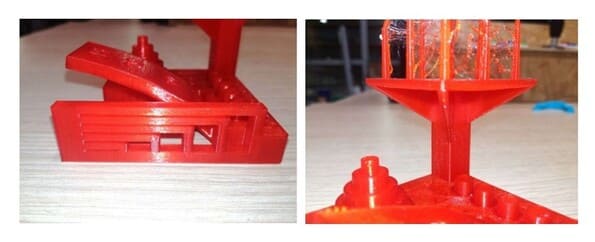
-
The inclination of a volumen, there is some roughness but it is not much, it is not so noticeable.
-
There is some roughness on the inside of the print made horizontally without support, but it has no hanging strips of material, is very acceptable and has a good finish.
-
In the final part of the test, we tried to see up to what thickness can be printed well, in this case, the thinner it was, the more deformity it showed, the material began to resemble a spider web.
ADDDITIONAL TEST
Another test without supports, inclined at 45°, the indicated printing time for our part was 1 hour and 37 minutes. I used the same parameters as the previous example.
The result looks good and there are no elements hanging.
MODEL:
FLASHFORGE GUIDER II VS ZORTRAX M200
- TIME:
The printing time is different, for the same model in FLASHFORGE GUIDER II the time was 3 hours and 57 minutes, while in the ZORTRAX M200 was 10 hours and 8 minutes.
- SURFACE:
The final surface, was much smoother on the FLASHFORGE II, while on the ZORTRAX M200, the material came out as strips, with irregularities.
- THICKNESS:
The thinner you print, the more likely the material is to break with the FLASHFORGE GUIDER II. In both there was a spider web finish in the thickness test.
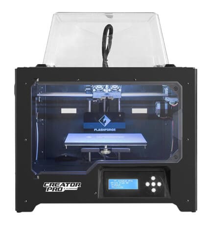
FLASHFORGE CREATOR PRO
Creator Pro is a straightforward 3D printer based on open source technology. It allows to upgrade and modify flexibly. Meanwhile, you are able to choose your favorite software as FlashPrint, Simplify3D, Cura and more.
-
Build volume: 230x150x140mm.
-
Weight: 14.8kg
-
Calibration system: Self-assisted
-
Materials: PLA, TPU95A, ABS, PETG
-
Extruder: 2 extruders.
-
Nozzle diameter: 0.4 mm
-
Connectivity: USB cable, SD card
-
Raft: The minimum raft thickness and the default value is 0.5mm
-
Slicing Software for 3D Printer: FlashPrint, Simplify3D, Cura and more
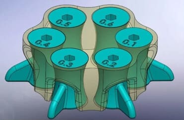
TESTING
We will use the following for tolerance test.
1.We are going to open FLASHPRINT, we can use other software but in this case we will use this one.
2.Click on PRINT and choose the MACHINE TYPE, in this case, the FLASHFORGE CREATOR PRO.
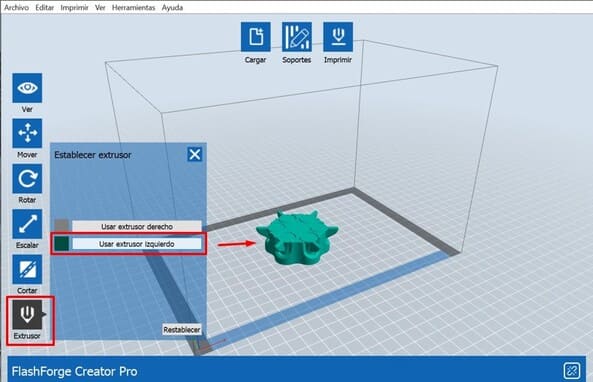
3.This machine has two extruders, but this time we will choose only one:
Click on EXTRUDER > USE LEFT EXTRUDER
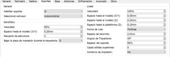
4.The parameters I used:
-
Material: PLA
-
Thickness: 1.75 mm
-
Extruder temperature: 200°C
-
Platform temperature: 50°C
-
Infill: 15%
-
Filling pattern: Hexagon
-
Raft: Enabled
-
Support: Disabled
The rest of the steps are the same as the setup we did in Flashprint for the Flashforge Guider II, except for the format to save, it will now be .X3G.
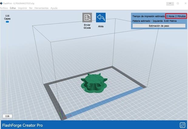
5.The indicated printing time for our part was 2 hours and 2 minutes. As you can see, the raft was also added for better results.
6.Then save the file in a SD CARD, find your file and follow the instructions on the touch screen, finish by clicking on PRINT.
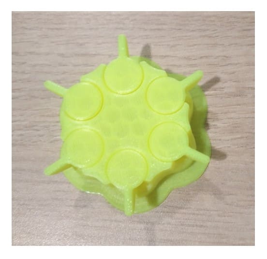
7.Gently remove the printed object with a spatula, also remove the raft, this is the result:
CONCLUSIONS
-
TOLERANCE TEST: This model had fused parts, so we could not confirm the tolerance, the pieces could not be separated.
-
Therefore, if you are going to use an example model, always verify that it can be used for the test we want to perform, especially if they are parts that will rotate or be removed.
-
FILLING: The filling was really great, apparently the final surface is too thin as the filling can even be slightly visualized.
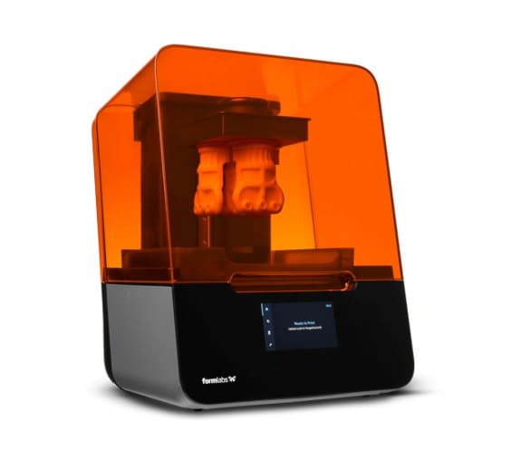
FORMLAB 3
Stereolithography (SLA) 3D printing has become popular for its ability to produce high-precision, isotropic and hermetic parts with a portfolio of advanced materials that enable precise details and a smooth surface finish.
-
Build volume: 185x145x145 mm
-
Weight: 17.5 kg
-
Calibration system: Automated
-
Materials: Resin cartridges
-
Biocompatible Materials: No
-
Technology: Stereolithography
-
XY Resolution: 25 microns
-
Laser Spot Size: 85 microns
-
Laser Power: One 250 mW laser
-
Layer Thickness: 25 - 300 microns
-
Connectivity: Wi-Fi, Ethernet, USB 2.0
-
Slicing Software for 3D Printer: Preform and Dashboard
TESTING
We will use the following file:
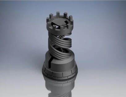
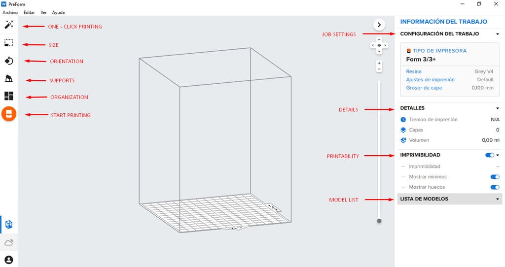
1.We are going to open PREFORM, it is a versatile and powerful slicing software for Formlabs 3D printers.
2.You will see the next options:
Right side:
-
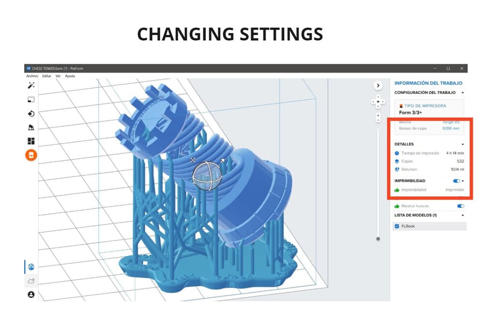
Job settings: you can set the printer type, media, layer thickness,etc.
-
Details: Here you will see the printing time, layers and volume that the part will occupy (According to its size and position of the part to be printed).
-
Printability: All the options should be with a green hand, which means that it is ready to print and there will be no problems during the process.
-
Model list: All the models loaded in the program will be shown here.
Left side:
-
One-click printing: with the symbol of a magic wand, it helps to orient, organize and add supports to your model (literally, just by clicking on this option).
-
Size: Helps to scale the part, either smaller or larger and see its measures in the X,Y and Z axis.
-
Orientation: We can change the orientation automatically or manually, rotate in X,Y or Z axis. You can also rotate according to the bounding box, changing the orientation helps us to have the best finished print (avoiding supports on the main surfaces) and change the printing time or use less supports, making the work much easier.
-
Supports: They help us that the piece has supports on sides that would be difficult to print without them, their absence would cause deformation in the piece, it is good to place them only in the necessary places, you can even eliminate some support points that do not affect the piece during printing (Check the 3 options of printability are in green).
-
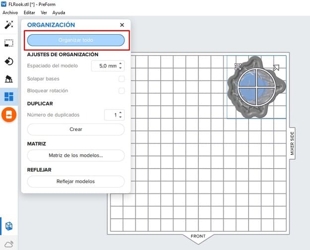
Organization: It helps us to place the part on the work table, if we want we can duplicate the part according to a distance or do it through a matrix.
-
Start printing: When your model is ready, you can click here and send the file to the 3d printer.
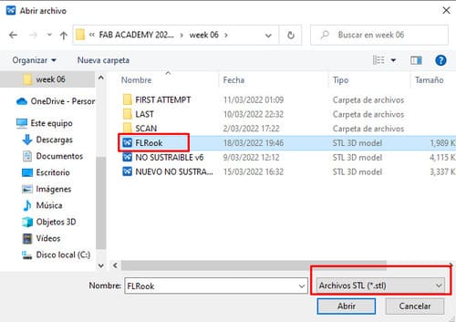
3.To open the file you must go to : FILE > OPEN, then find the folder where you have the file in .STL and click OPEN.
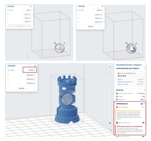
4.I imported the file in millimeters, but it was too small to print, so I had to resize it and make it bigger with the SIZE option.
5.The IMPRIMIBILITY section comes out with an error, it tells us that we must add a base and supports, so I rotated the piece with the ORIENTATION option, this way the surface that looks to the outside will be free of supports (avoiding that they leave some irregularity) and only the internal parts will have those supports.
6.Do not forget to choose the type of printer, type of material, print settings and layer thickness before adding the supports, I chose:
-
Printer: FORMLAB 3
-
Resin: Grey V4
-
Print setting: Default
-
Layer thickness: 0.100mm
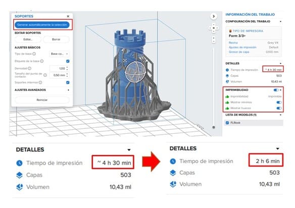
7.I added the supports automatically, now the ‘PRINTABILITY’ part is with the little green hands, which is a sign that our file can be sent to print.
8.We also see the printing time that indicates ~4h 30min, this is only an approximate time, clicking on it, it will recalculate the exact printing time, which in this case is 2h 6min.
9.Now, click on ORGANIZATION > ORGANIZE ALL and it will be placed correctly on the printing table.
10.We can send it directly to print if the laptop is connected to the machine or also save it in the .FORM format, so that we can open the file with all the settings made on another laptop.
I was about to send the file to print but there was not the type of resin I had chosen, I had to change it to Tough V5 and the instructor suggested me to turn the piece a little bit to make it easy to remove the supports since in the previous position it was going to be very complicated.
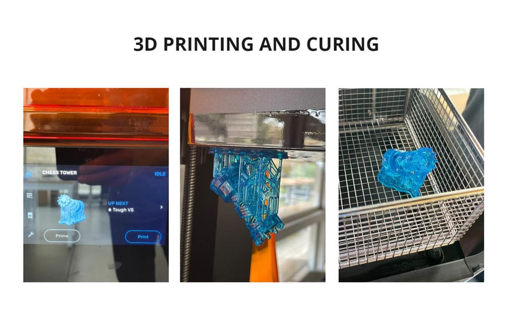
11.The file is sent from the laptop to the machine (being connected through a USB port), then it will appear on the touch screen our object to print, we click PRINT and it will indicate us that we must add the material, it is carefully placed with the lid open.
When we click NEXT, it will ask us to verify if the printing bed is placed, finally the machine starts to verify that everything is ok to start printing.
12.The 3d printer starts to warm up, balances the resin and print bed.
The printing bed descends and the laser light starts to solidify the resin, with this we obtain the 3d printed figure.
13.Once finished, the printing bed is removed, then it is placed in a special washing machine for resin, eliminating resin residues that do not belong to the piece.
Then it goes into the washing machine for 20min. After washing, the printing bed is removed and the piece is removed with a spatula.
14.Spray a little isopropyl alcohol to the piece and place it in the curing oven, set the temperature and curing time. This design took 1 hour for this process at 60°C.
15.Finally we remove the piece and this is the result:
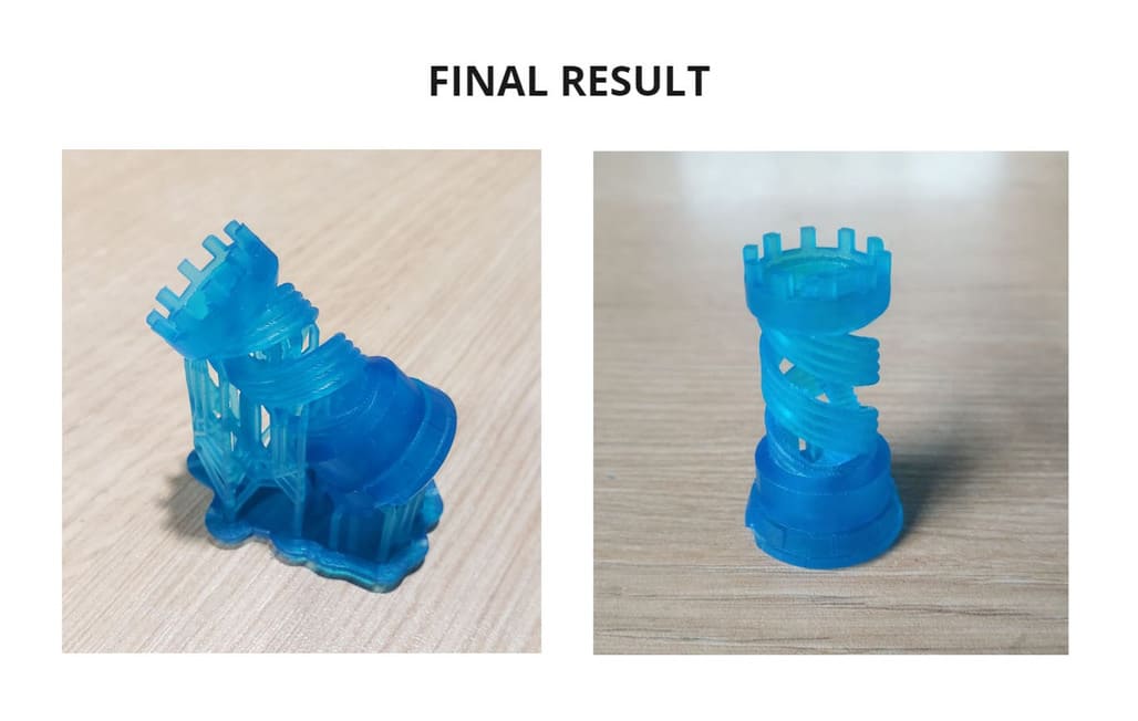
CONCLUSIONS
-
The resin is made for parts with a lot of detail, which would be almost impossible to realize by other methods.
-
Prototypes can be easily made, avoiding errors and additional costs in large scale productions.
-
The finish is as identical and clean as possible in terms of surface and as close as possible to the 3D model, especially for difficult surfaces.
-
It is more resistant after curing the piece, I would be encouraged to make my own custom jewelry designs or other pieces for my daily use, there are many variety of projects in which the use of resin can be employed, it has also been used for stop motion in films.
2. INDIVIDUAL ASSIGNMENT:
3D PRINT NOT SUBTRACTIVELY
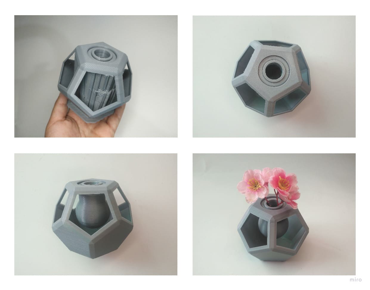
As in Computer-Aided Design week, I chose Fusion 360 and designed a part that could not be easily made subtractively.
The object I design cannot be made by a machine that subtracts material, because it would destroy the bodies, it is composed of 3 bodies, one static and 2 rotating, it can only be made by 3d printing.
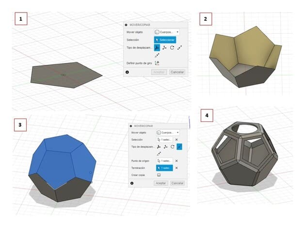
1.First, I started by making a circumscribed polygon of 5 sides and 25mm radius, I converted it to PATCH.
2.Then I made a copy of that face with the MOVE tool (with check in the COPY box) and rotated it to 116.57°, then applied the CIRCULAR PATTERN tool, converted it to a single body with the STITCH tool.
3.I duplicated the whole volume, rotated it 180° and used the MOVE > STITCH tool, indicating a top corner and a bottom corner that should fit, we use STITCH again and it becomes a single volume.
4.I applied CHAMFER of 3mm and applied SHELL in 5 faces, but in the upper part I used the volume of a circle and subtracted it(It remained a circular hole).
5.Taking as reference the center of the bottom plane, I placed the measurements of the image to match the one we made in the previous step. (The radius of 3.50mm must change to 3.45 mm so that the piece can rotate).
6.I added a semicircular shape.
7.Apply REVOLUTION to each sketch.
8.I moved the volume to the top to make it fit, thanks to the POINT TO POINT tool.
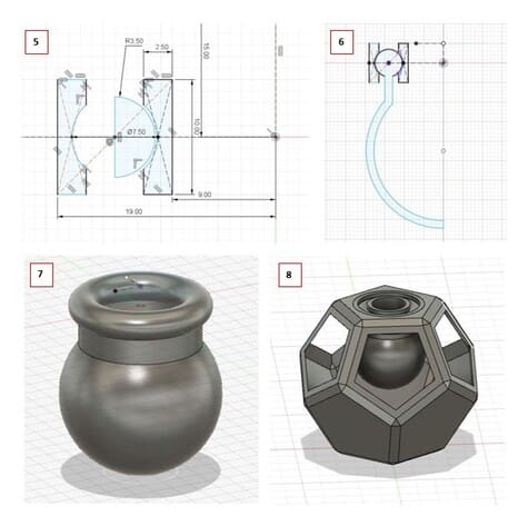
9.To save the file outside of Fusion 360, you must click on the file name, in this case NOT SUSTAINABLE (that’s how I named it) > SAVE AS MESH.
10.Save the file with the following parameters: .STL, MILLIMETER, ONE FILE and the HIGH, finally click on ACCEPT.
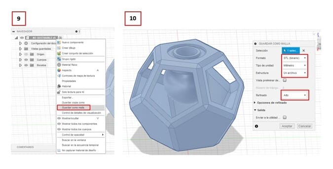
11.I used Flashprint to send the file to CREATOR PRO, but the program indicated a WARNING, I ignored that warning, the media failed to print and it looks awful.
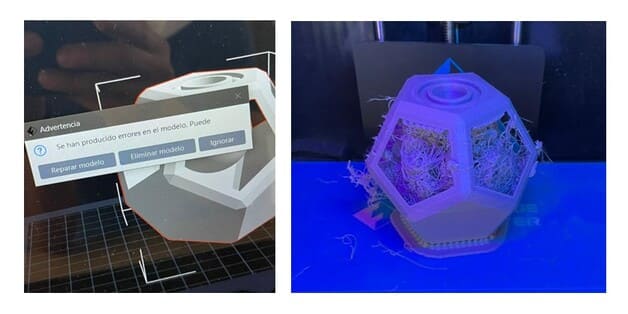
12.Finally I could find the mistake, two static volumes of the upper part were not joined, so I joined them, which you can see in the step of the photo N° 10 (I corrected, took the photo again and added it).
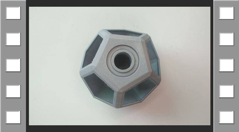
Now, this is the result and I added correctly the supports, the inner sphere rotates thanks to the shape it has, in total there are 3 bodies, one static and two rotating.
VIDEO

3D SCAN AN OBJECT 
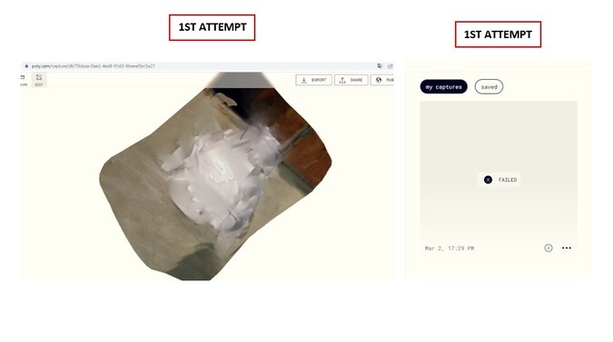
The previous assignments were made when I still had access to the lab, but currently it is not possible to access.
I tried to use other applications like Polycam, but it didn’t work, I even changed the background and took more pictures, but the application showed the message: FAILED.
So I tried another application that could only be used from IPHONE (my brother lent me his) and that’s how I came to use QLONE.
QLONE
I decided to use Qlone because I have seen that it works easily together with a scanning mat, in which we place our object.
TESTING
I used a small panda-shaped object so I could use it on an A4 sheet, these are the steps I followed:
1.I downloaded the QLONE app, then I opened the app and downloaded the scanning mat in A4 format, remember that the surface must be matte and not glossy.
You can use this link to download it: QLONE MAT
You can print it in the scale you want, either A4, A3 or more, it will depend on the printer you have and the size of your object.
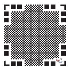
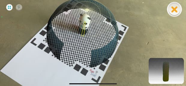
2.When you place the object on the scanning mat, a sphere will appear around it. If you see a red color, it means that the object is too big or badly placed. In this case I got a gray sphere with yellow lines, that means it is ok and I started to pass the cell phone around it, until the sphere disappeared.
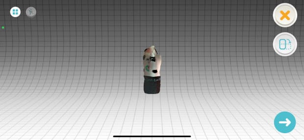
3.This is how the first attempt looked like, you have the option to make a second pass and the result will be closer to how the object really looks like.
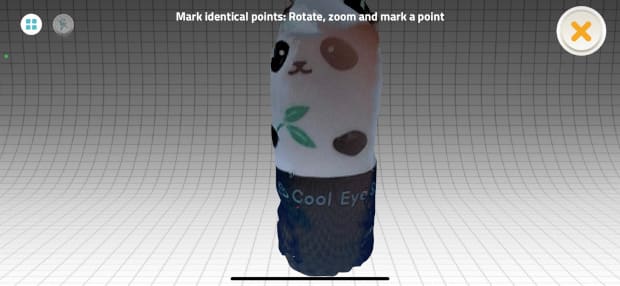
4.This is the final result, I remind you that you can export it in different formats like .STL, .OBJ, IMAGE, VIDEO, SketchFab or other platforms. (Some of these options are free and others are paid).
It is not perfect but it looks better than the previous one and can be improved within the same application.
3. WHAT HAVE I LEARNED?
-
To handle 3D printers, both for SLA and FDM, I am very curious to be able to apply this technology in everyday objects, which could solve problems and improve our quality of life.
-
Customization is one of the things we can do thanks to these printers, which I think is fantastic, and also the fact of having a quick prototype, perfecting it, and then being able to produce it on a large scale and without errors.
-
The technology has advanced so much that we can do 3D scanning using a cell phone application. You can even edit the surface in the application itself, especially if you are in a hurry. Although there are also professional scanners, they are more expensive, I hope to try the Fab Lab scanner when we can access the lab and be able to notice the differences.