Final Project
Questions about Final project requirements: ANSWERS
1. SLIDE
2. VIDEO
3. DESIGN
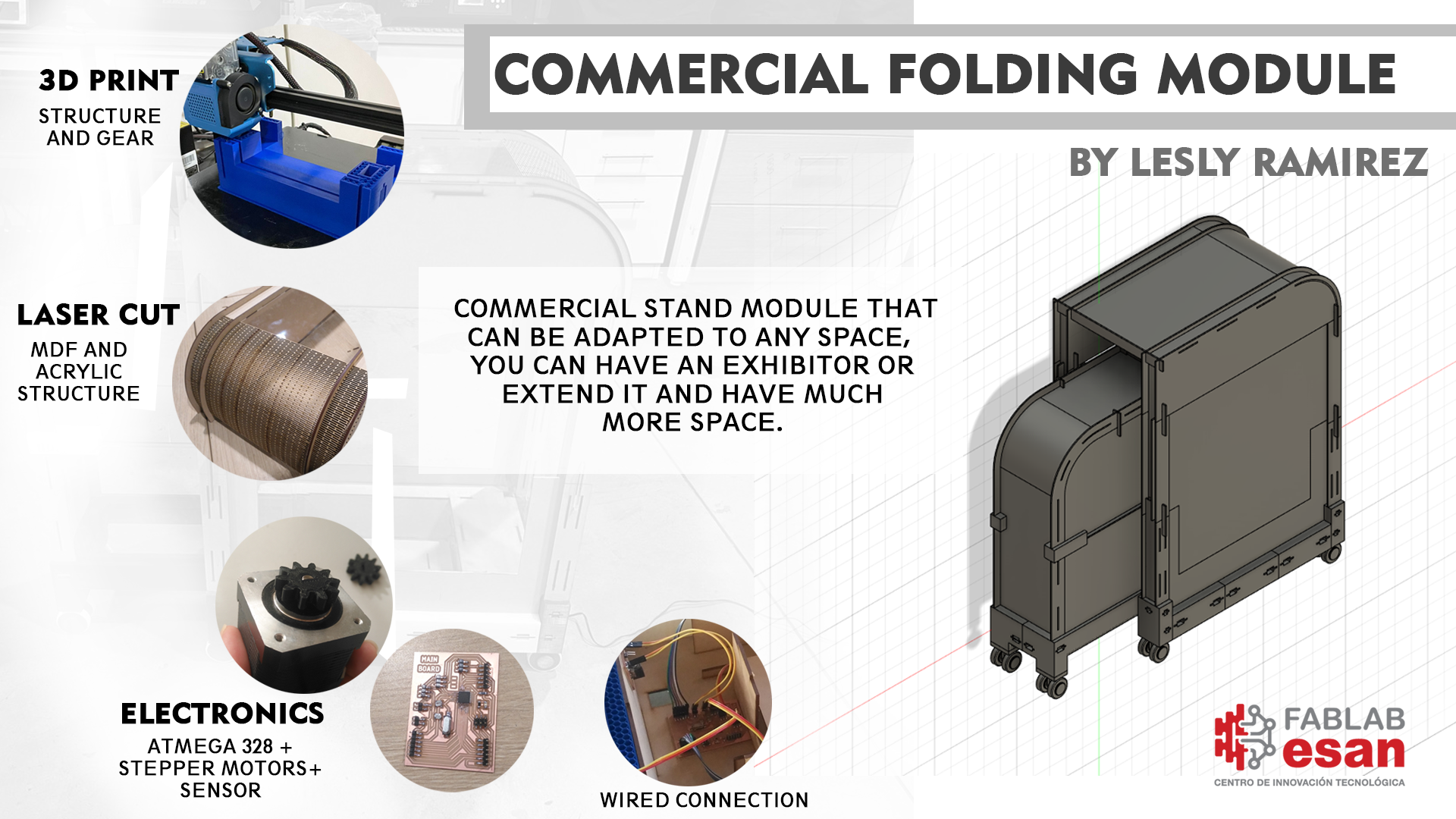
My design is a commercial folding module, here I show you the process of how I developed the project:
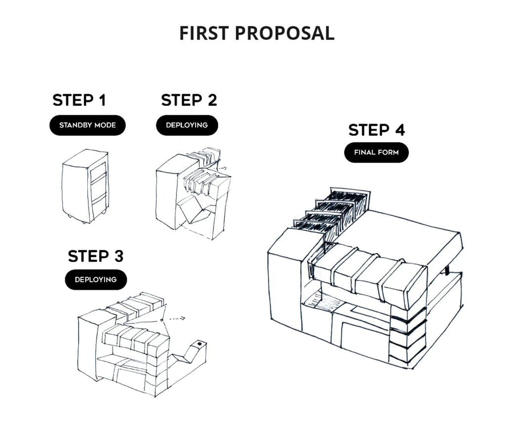
3.1 INITIAL APPROACH
My first proposal was a 2.5 x 3m module, it was too big but that was the initial idea.
It was really big and complex, the module went from the size of a suitcase to a size larger than 6m2.
You can see more details in this section of my website: PRINCIPLES AND PRACTICES
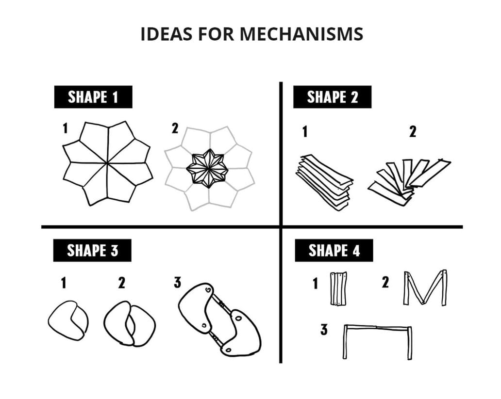
During the COMPUTER AIDED DESIGN WEEK, I have researched the different mechanisms that can be used and these are the main proposals:
SHAPE 1: It uses a mechanism similar to an umbrella as it opens and closes. The difference would be the final shape, I wanted to use it for the top of the counter or as an umbrella, protecting both the customers and the vendor from the sun.
SHAPE 2: Rotating mechanism on an axis, this works great when the surface between the elements is flat or smooth, but you have to take into account the weight, if it is too heavy, the structure will probably tilt.
SHAPE 3: This mechanism uses shafts, based on the connecting rod and crank, I wanted to use it to extend the module.
SHAPE 4: This mechanism is based on the accordion riveter and how many folding furniture I have seen on the internet work.
Then I tried to simplify and focus on what was the main mechanism in which the pieces would move, I made two proposals:
OPTION 1: Lateral sliding. OPTION 2: Accordion type axes displacement.
The difference is that the heights of the elements change in the second option, but this affects the stability of the rest of the design.
I managed to join both mechanisms and you will see it in the testing process, but I only used option 1 for my final project, because I had never made a mechanism and it was very complicated to make a very complex structure, I hope to do it for future projects.
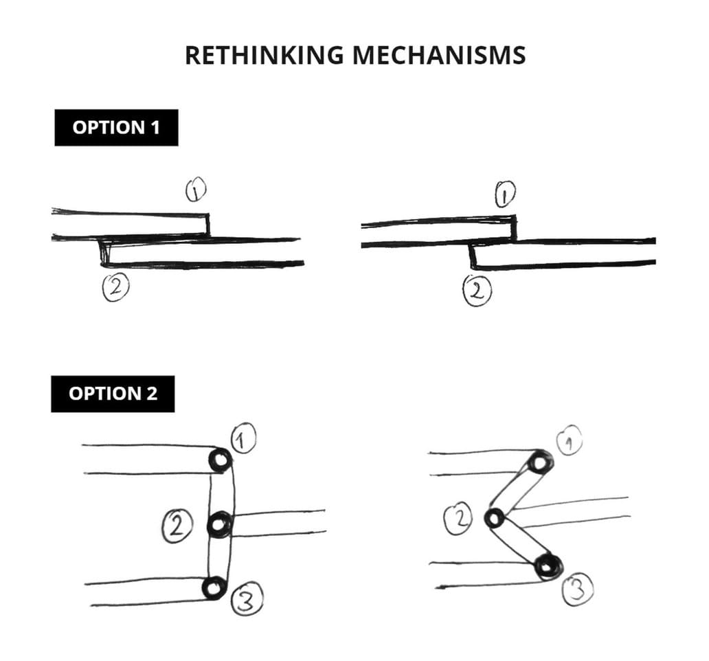
One of the main conclusions I came to is that I had to use the displacement mechanism (option 1).
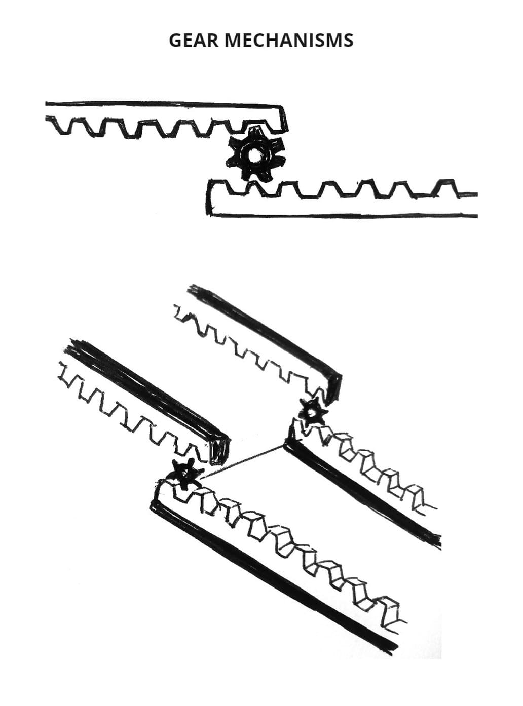
HOW WAS IT GOING TO WORK?
Gears are a type of mechanism that we can find in different structures. I decided to use it in its most basic form so that I could control it and make it work with my structure.
This gearing achieved the lateral displacement of volumes, so that’s how I applied it in my design.
You can see a graphic description below:
According to the chosen mechanism, I started to design the module, but this time I chose to make it smaller in order to test and prove its operation, advancing in a spiral process, from the most basic to the most complex.
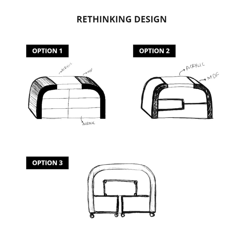
All the designs are raised to use MDF and acrylic as structure, in order to have a good support and to be able to visualize the products on display. These are the 3 options:
OPTION 1: A simple design in which you can add the scrolling mechanism using gears.
OPTION 2: This is asymmetrical in the internal divisions and I thought to apply the mechanism based on the connecting rod and crank.
OPTION 3: Here I combined the axle mechanism(mechanism based on the connecting rod and crank) + the horizontal displacement mechanism with gears.
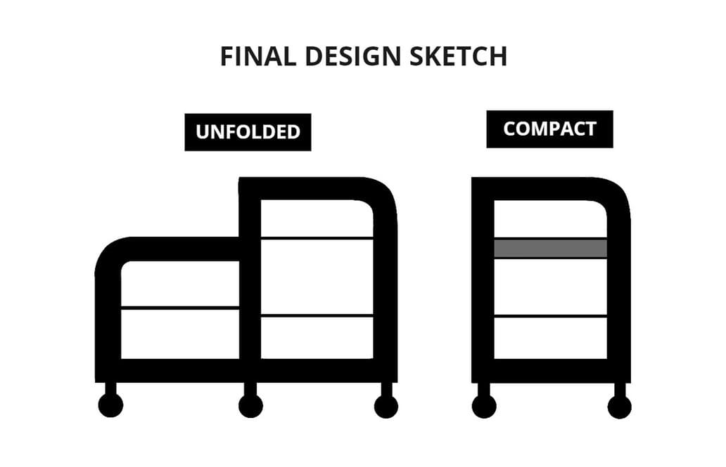
FINAL DESIGN SKETCH:
Finally I decided to use the horizontal displacement using gears, it is similar to opening and closing a drawer. This design has one part bigger than the other so that when folded, one part of the module fits with the other, making it more compact.
3.2 STRUCTURE
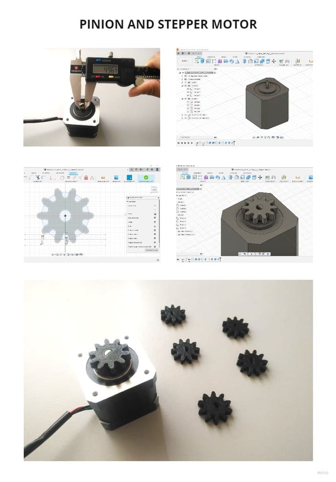
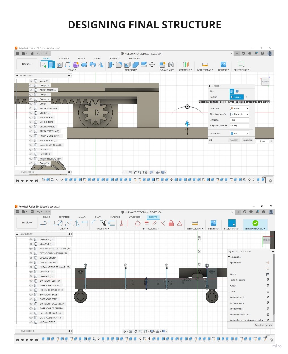
In order to make the main structure and mechanism, I had to measure the type of motor that was going to work together with the gears.
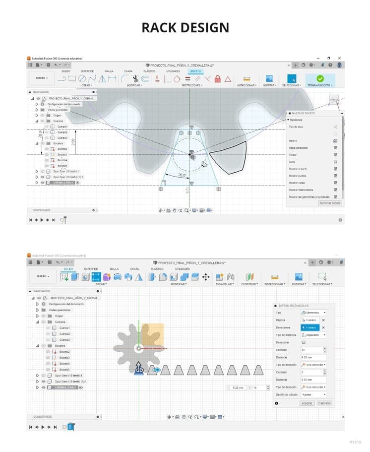
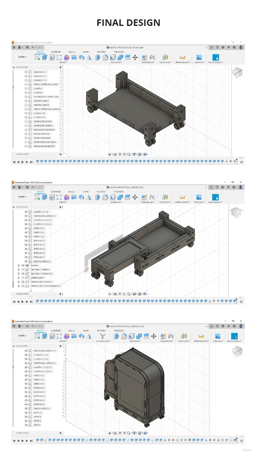
After measuring the stepper motor, I used FUSION 360 to build up the volume in 3D. Then I followed a tutorial where I learned how to make the calculations to be able to design the pinion, you can see it in the following link:
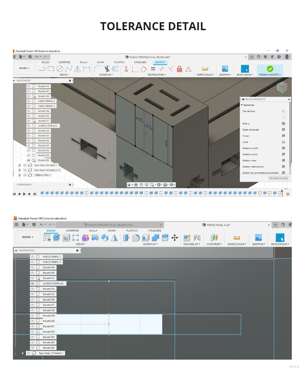
I had to change the tolerance of the pinion design several times so that it could fit the motor and it finally did.
You can see the process and results in the following pictures:
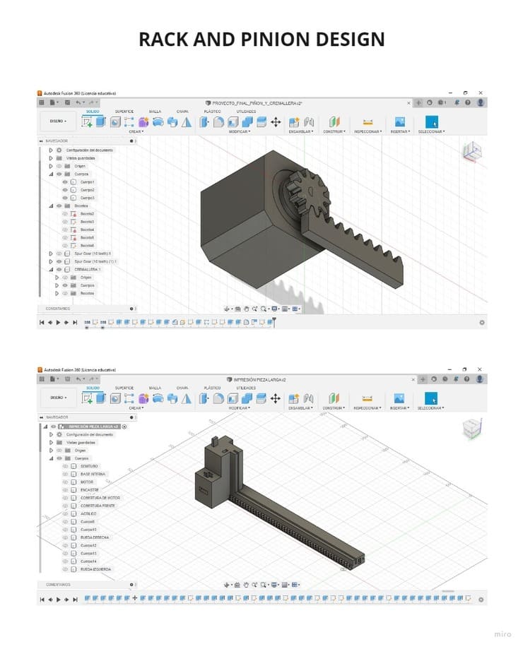
In the same tutorial I found how to make the rack so that it can work together with the pinion, so based on that I started to develop the whole rack and the support structure.
I made the structure and made modifications several times, thinking about the parts that were going to be attached such as MDF and acrylic.
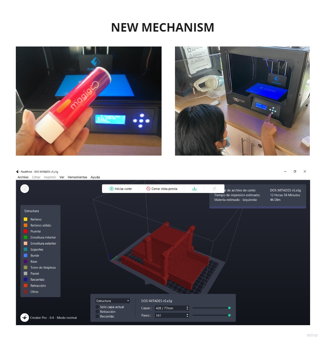
Because the 3d printer has a delimited work space, my piece could not exceed certain measures, so I decided to divide them and then I could put them together as if they were lego pieces.
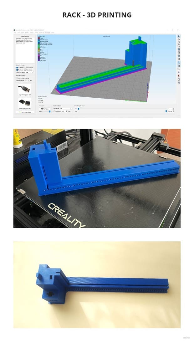
I used the Creality printer to print the first piece of the structure, you can see more about the steps to follow to prepare your file in the following link: 3D SCANNING AND PRINTING.
The filament I used have the following characteristics:
BRAND: ESUN FILAMENT
1.75mm PLA
COLOR: Blue
QUANTITY: 1KG
PRINT TEMP: 205 -225°C
For the first piece I printed , I used brackets only in necessary areas and also added a raft.
This part took 22h 57min to print and used 180.97g of filament.
I printed the part diagonally because there was no other way it could fit on the workbench.
The result was good but the thicknesses of the sockets into which the MDF and acrylic were to fit, varied depending on the position, so before designing and printing more pieces, I had to make tests.
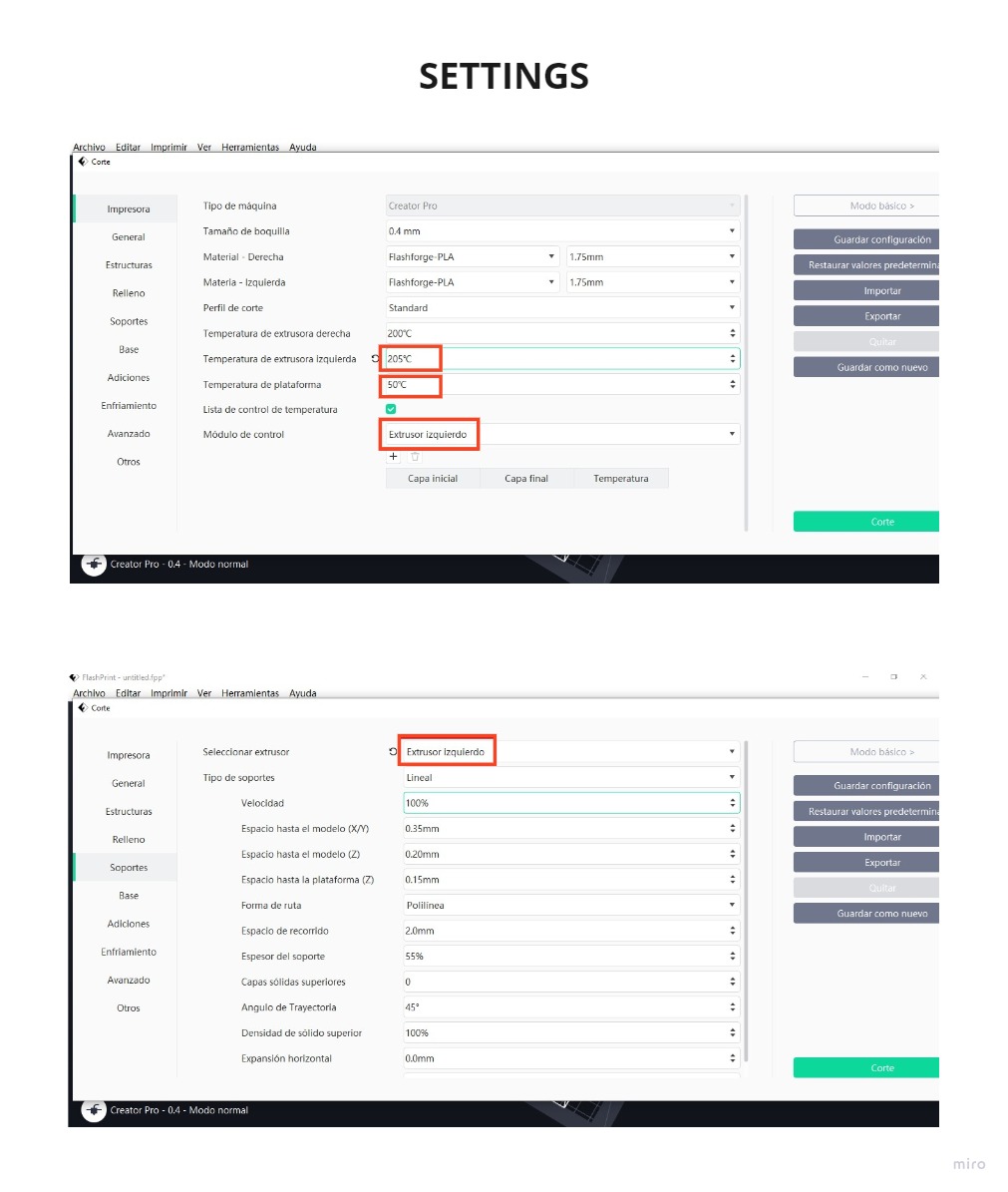
The settings I used for printing were:
EXTRUDER TEMPERATURE: 205°C PLATFORM TEMPERATURE: 50°C RAFT: On SUPPORTS: On (automatic) FILLING: Hexagonal
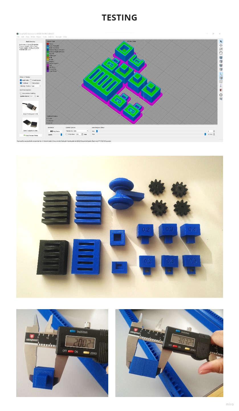
I designed small but necessary parts to be able to continue with my design, so I could test the fits and tolerances of 3D parts that went with 0.2, 0.3 and 0.4 clearances.
The best tolerance between 3D parts was 0.2.
I also did tests for the MDF and ACRYLIC, whose proper KERF was 3.10mm for both, as I wanted the MDF to be tighter so it would not allow the module to come apart and the acrylic to be not so tight so it would not break from too much pressure.
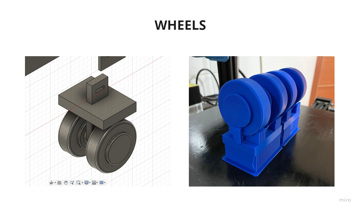
Additionally I designed the wheel for my module, I came to the conclusion that it needed a tolerance of 0.35mm between the wheels and the structure. It needed a surface that would allow it to slide, as its current shape could not move on some surfaces.
I also noticed that there are a few extra millimeters depending on the way the piece is printed:
Single piece sides : 0.02
Printed side from the base joining two pieces: 0.32mm additional, i.e. each printed piece has 0.18mm additional if measured from the base on which it was printed (having already removed the raft).
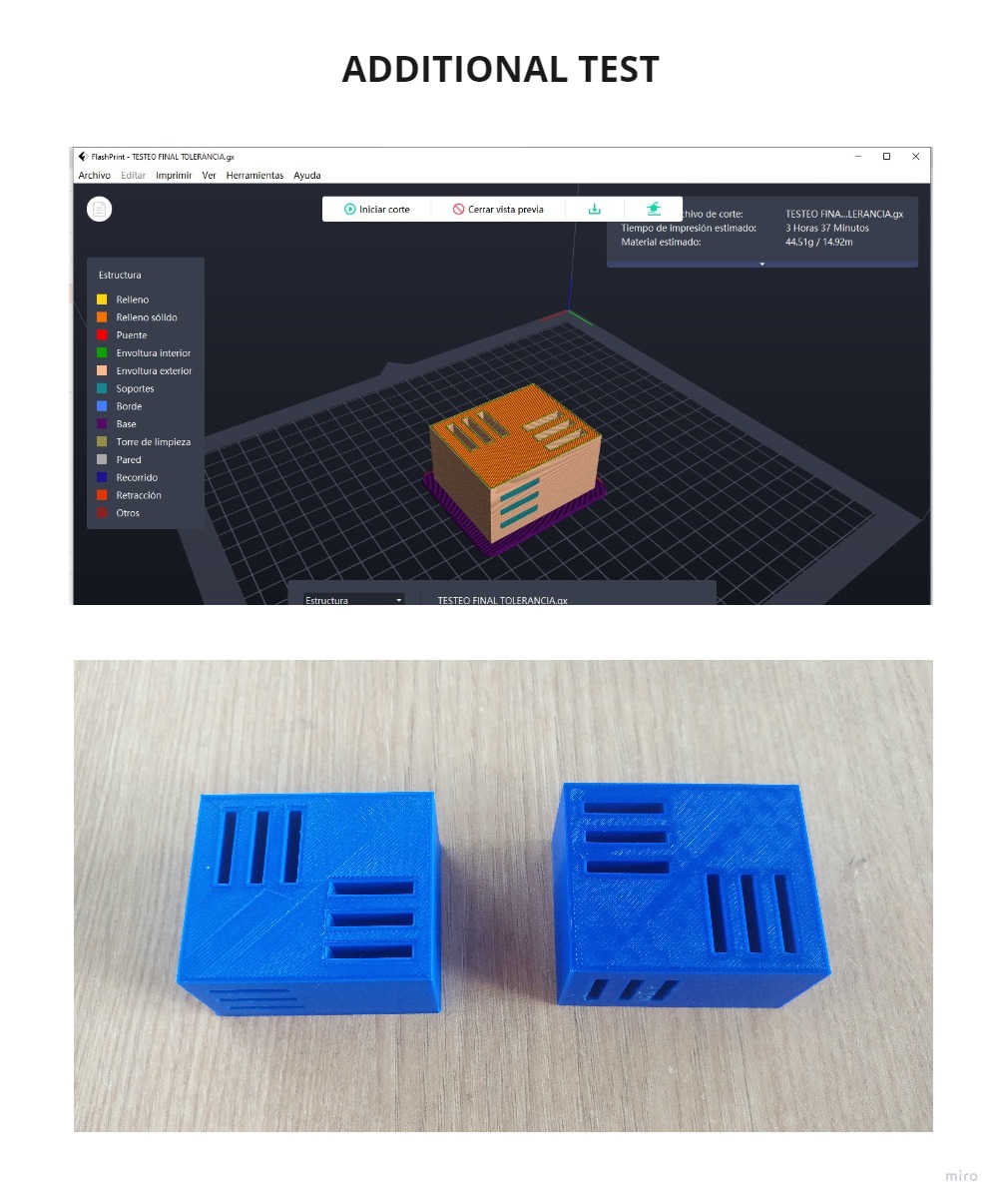
I noticed that the tolerances change depending on the position in which it is printed, I did two more tests, for the different printers I was using, the FLASHFORGE GUIDER II and the CREALITY.
The perfect tolerance is 3.10mm but when printed vertically it changes to 3.30mm (Flashforge Guider II) or 3.40mm (Creality printer).
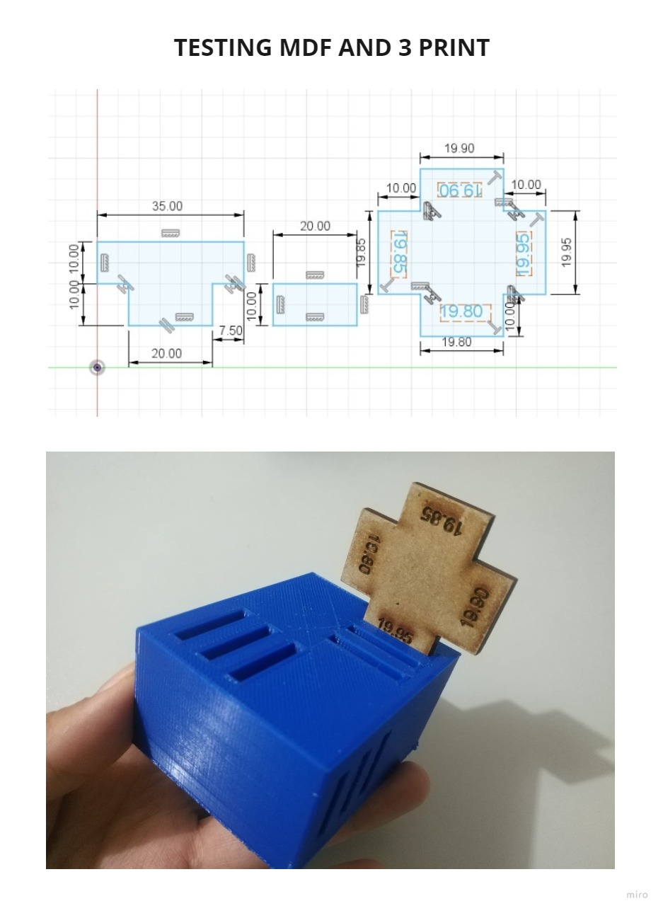
I cut pieces in MDF as in the assignment of COMPUTER CONTROLLED CUTTING, in the group assignment section.
There were different results for the widths depending on the position of the impression, I used the value of 20 mm as a base, but the widths varied from 19.80 mm to 20.05 mm.
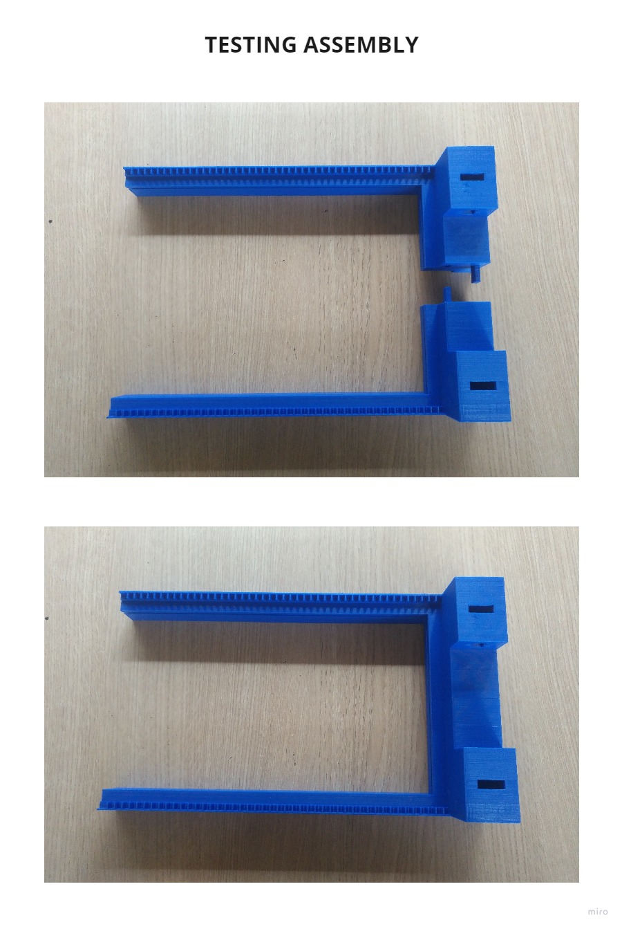
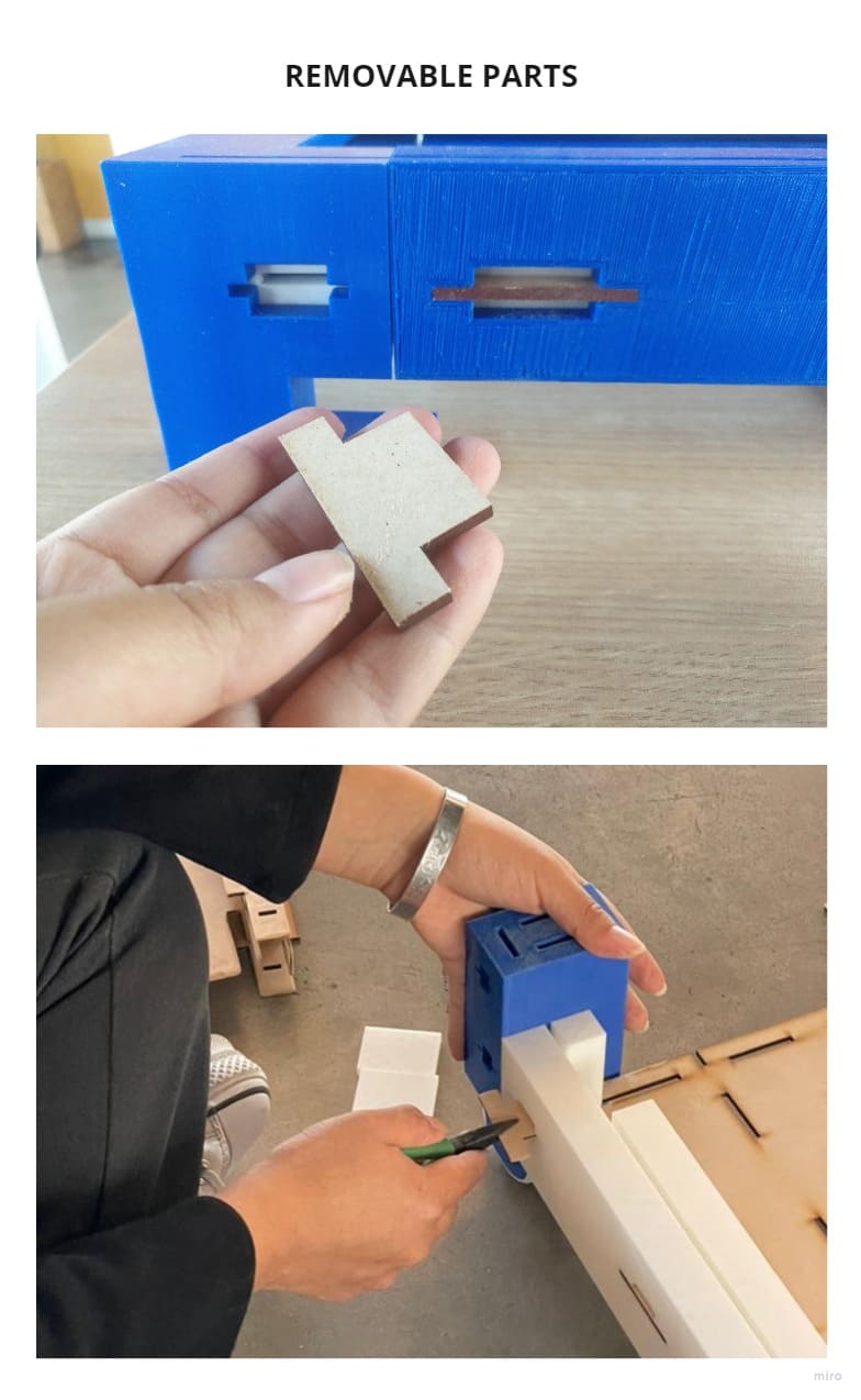
After changing the tolerances, the pieces joined easily, but it did not support much pressure, when I tried to add the rest of the pieces, the union made in 3D printing broke.
So I had to make modifications in the design, all the joints would be with 3D and MDF to avoid disassembling the project, everything will be made with pressfit.
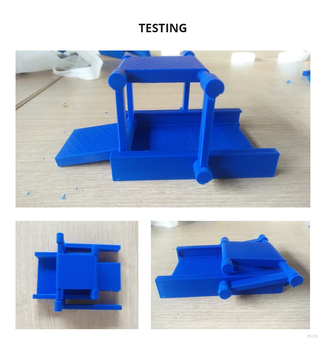
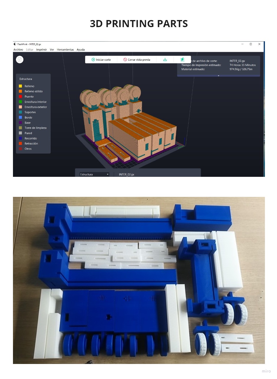
You can see how the first test pieces started to be assembled, each one took about 24 hours to be printed in the CREALITY 3D printer:
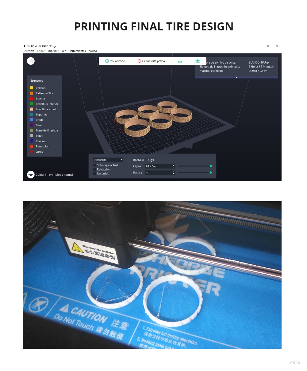
On the other hand, I also had to use TPU filament for the rims and cover the wheels with PLA, this way the mechanism works on any surface.
The printing characteristics were:
MATERIAL TYPE: TPU 95A
CUTTING PROFILE: Standard
EXTRUDER TEMPERATURE: 225°C
PLATFORM TEMPERATURE: 50°C
A single piece takes 38min to print, I used the FLASHFORGE GUIDER II printer.
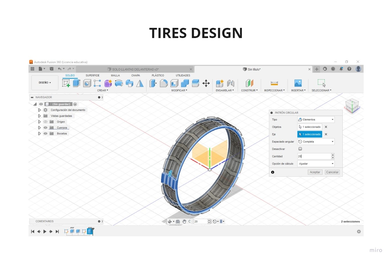

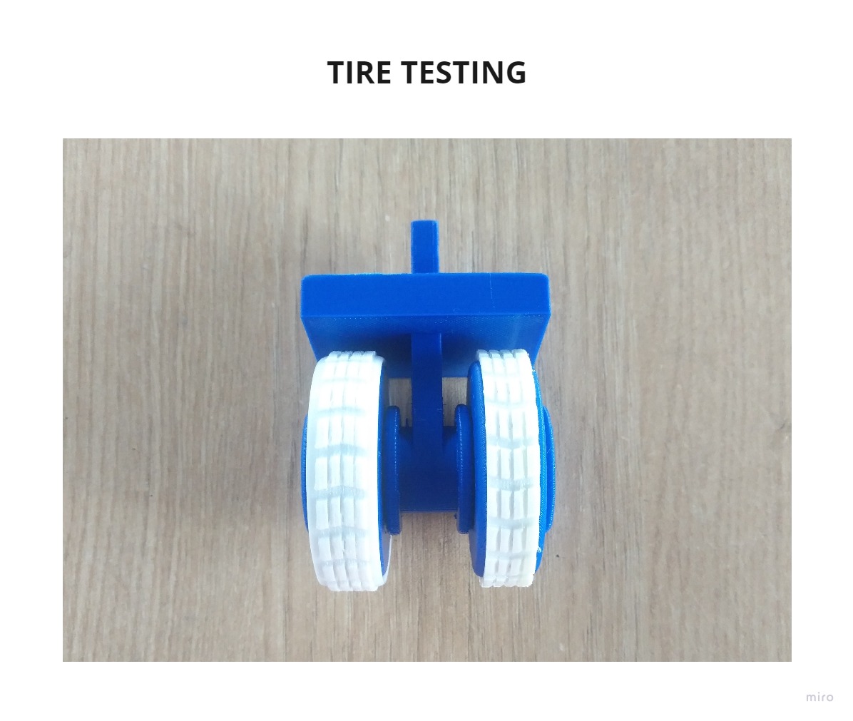
After printing, I made the test and the result was that the TPU rim came off after rolling several times, so I modified the design and made more tests, I tried to make it thicker, more curved and it didn’t work either because being thicker it was less flexible and couldn’t fit with the wheel.
Finally I made another rim with the same characteristics of the first test but with a small and slight curve on the sides, the result was impressive, it adhered very well without glue, everything was under pressure, so I decided to print more for the rest of the rims I would use.
I printed in two times, first 6 units and then 6 more because I would use 12 in total.
I also designed a mechanism to merge the proposals I had initially, I will develop it in more detail in the future for other projects, but I was able to confirm that it is possible and it works.
After many changes I managed to make the design, taking into account the mechanism, the sockets and the tolerance, I changed some parts of the sockets according to the position in which they were going to be printed, they are just 0.2mm of difference, but they are very important for the design to work, you can see it in the photo of TOLERANCE DETAIL.
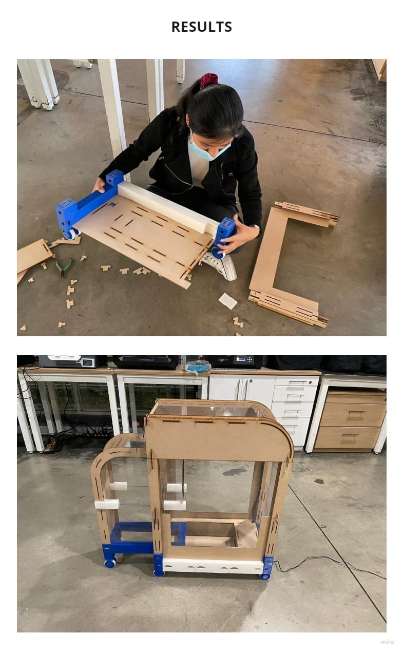
The structure of my design worked in the simulation and has more than 50 pieces on the bottom, it was the hardest part to design, it will be made of MDF, ACRYLIC and 3D PRINTING.
Everything is joined with pressfit.
It was many hours of printing, in some cases 72 hours as you will see in the following images, it was many hours of printing, I could say almost two weeks.
Then I started to assemble the 3D parts and also to laser cut the remaining parts.
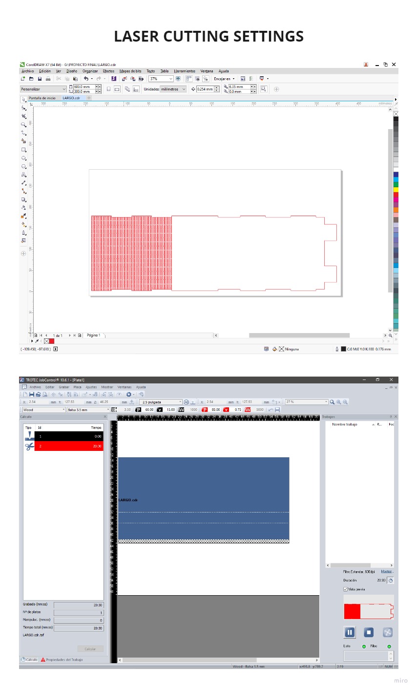
I exported my file from FUSION 360 to .DXF, I opened this same file in COREL DRAW to send the parameters to the SPEEDY 400 laser cutter.
For laser cutting of MDF, the parameters were:
POWER: 85
SPEED: 0.75
FREQUENCY: 5000
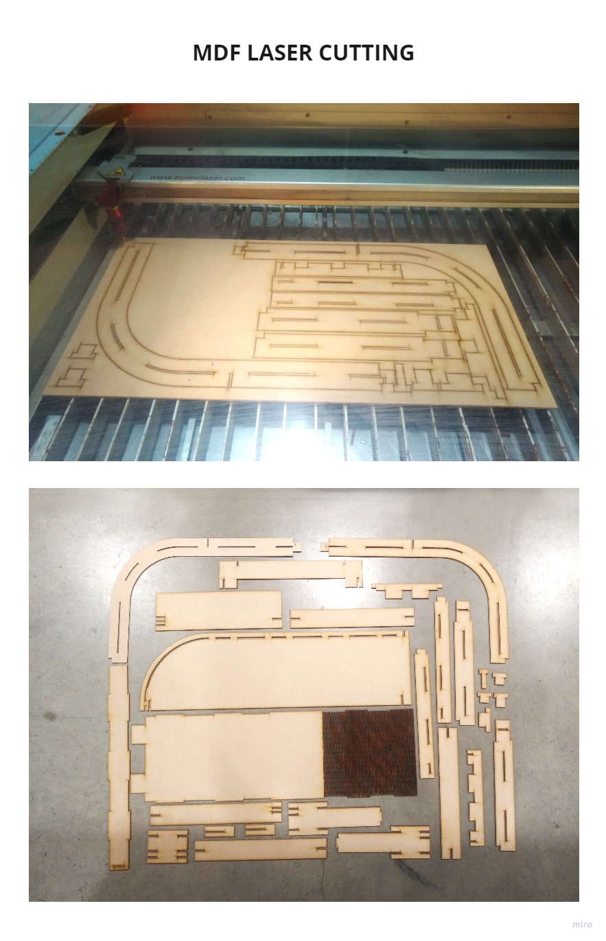
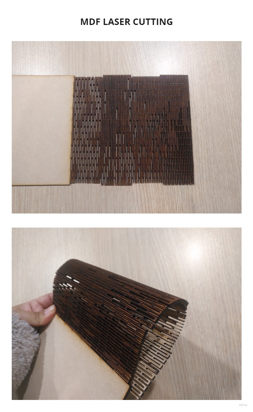
I cut several sheets of MDF but all the pieces did not fit in a single photo, so I only used a few to show you the result.
You can see the flexibility of MDF to make curved shapes thanks to a cutting pattern.
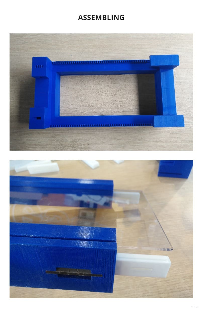
4. ASSEMBLY
The pieces were fitting together and I only used MDF and 3D printing for the main structure and clear acrylic on the front and back, so that the products could be displayed.
To assemble the whole module, I had to make modifications due to the fit of the pieces, especially for the wiring, I reprinted some 3d pieces because the tolerance suffered slight changes. I also re-cut some pieces of MDF because I had to modify the base due to the position of the electronic components, especially for the sensors.
5. ELECTRONICS DESIGN AND FABRICATION
At this stage, I realized that I had to have more than one board layout, dividing into the main board that has the microcontroller which will be connected to the power supply and the other input and output boards.
I performed tests on the INPUT and OUTPUT assignments of the week in which I defined that I was going to use limit switch sensor and stepper motor.
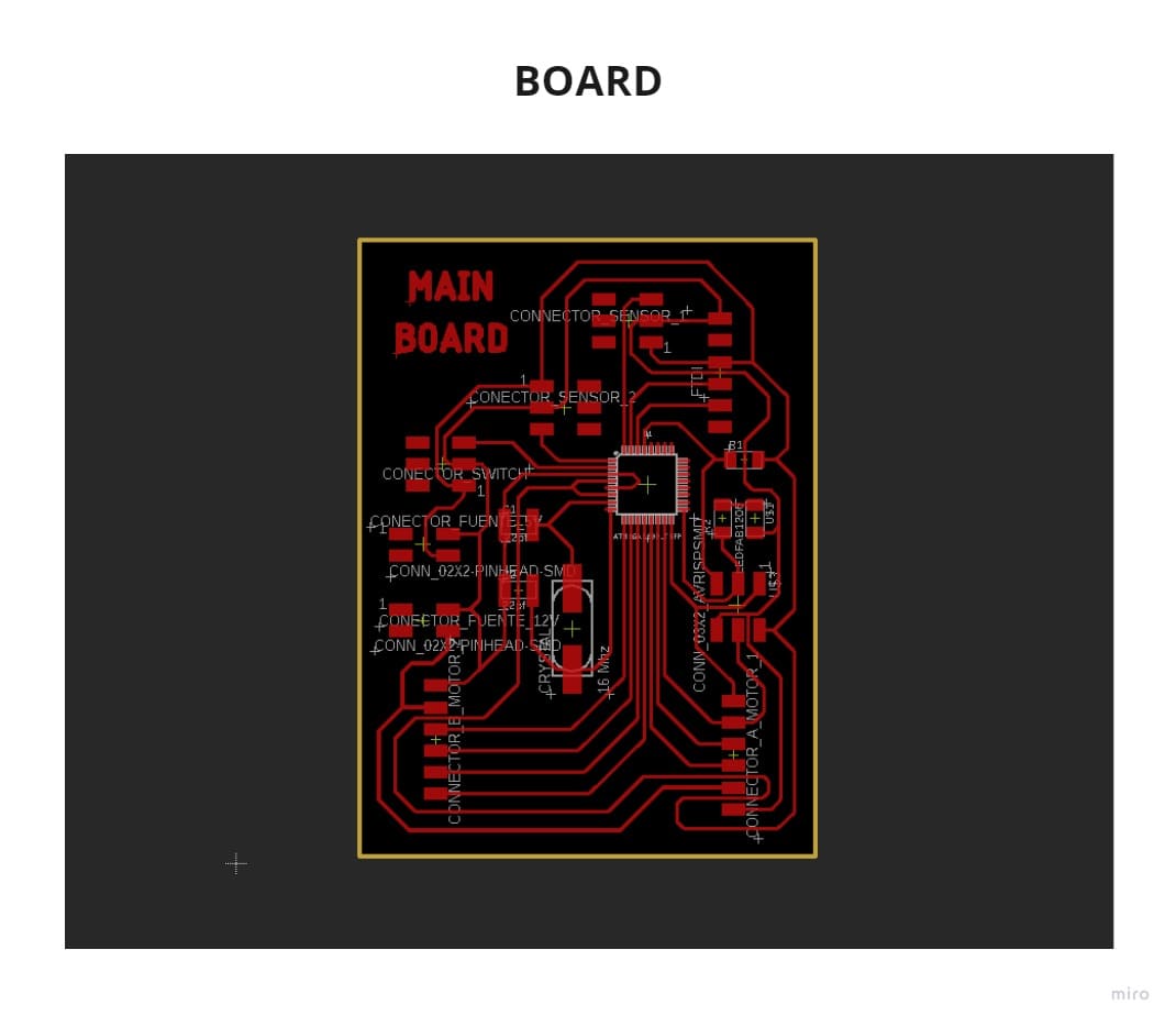
5.1 ELECTRONIC DESIGN & EMBEDDED PROGRAMMING
I based my design on Satshakit’s design to be able to understand the operation and to be able to program in ARDUINO IDE without problems and in a very simple way. But my design has modifications, mainly because I had to divide it into sub boards according to the needs of my project.
This board was the most difficult one, because when I applied the design rules I got the message “ERROR”, the Atmega328 library had the pads too close together, so I had to edit the library.
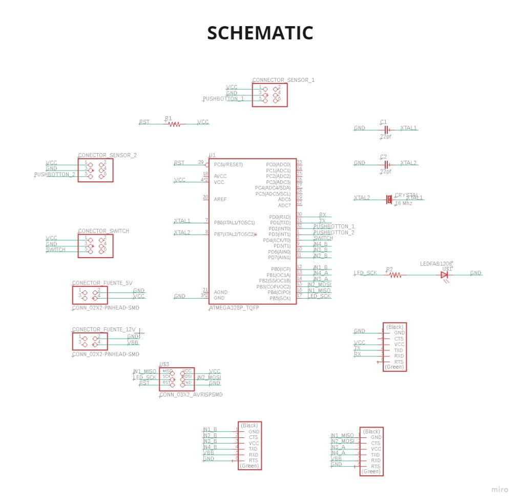
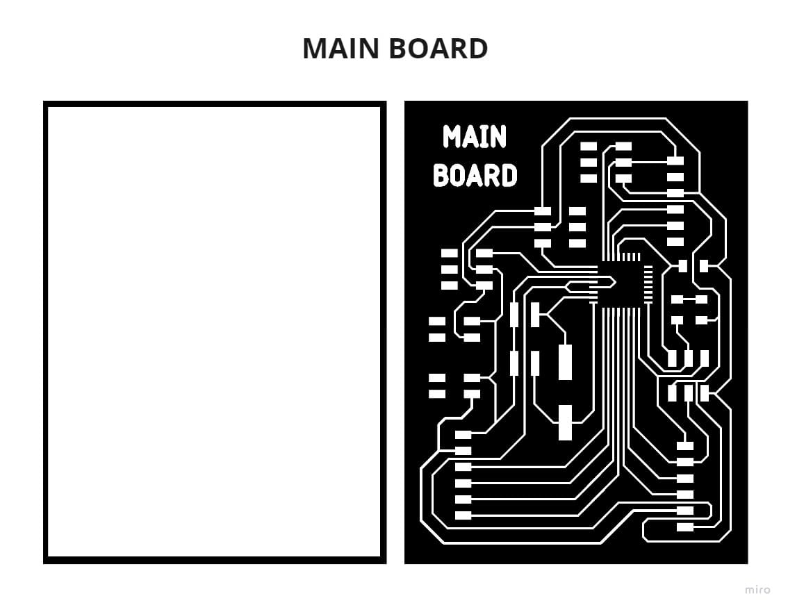
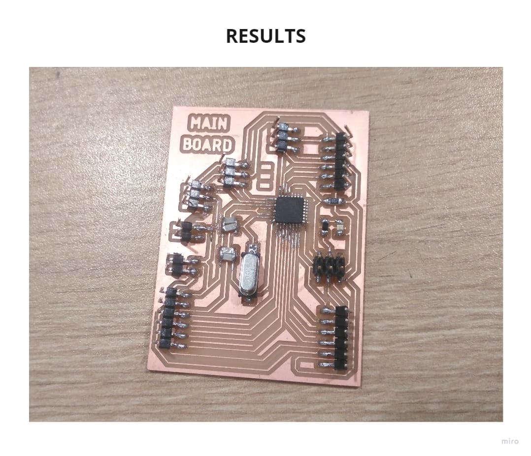
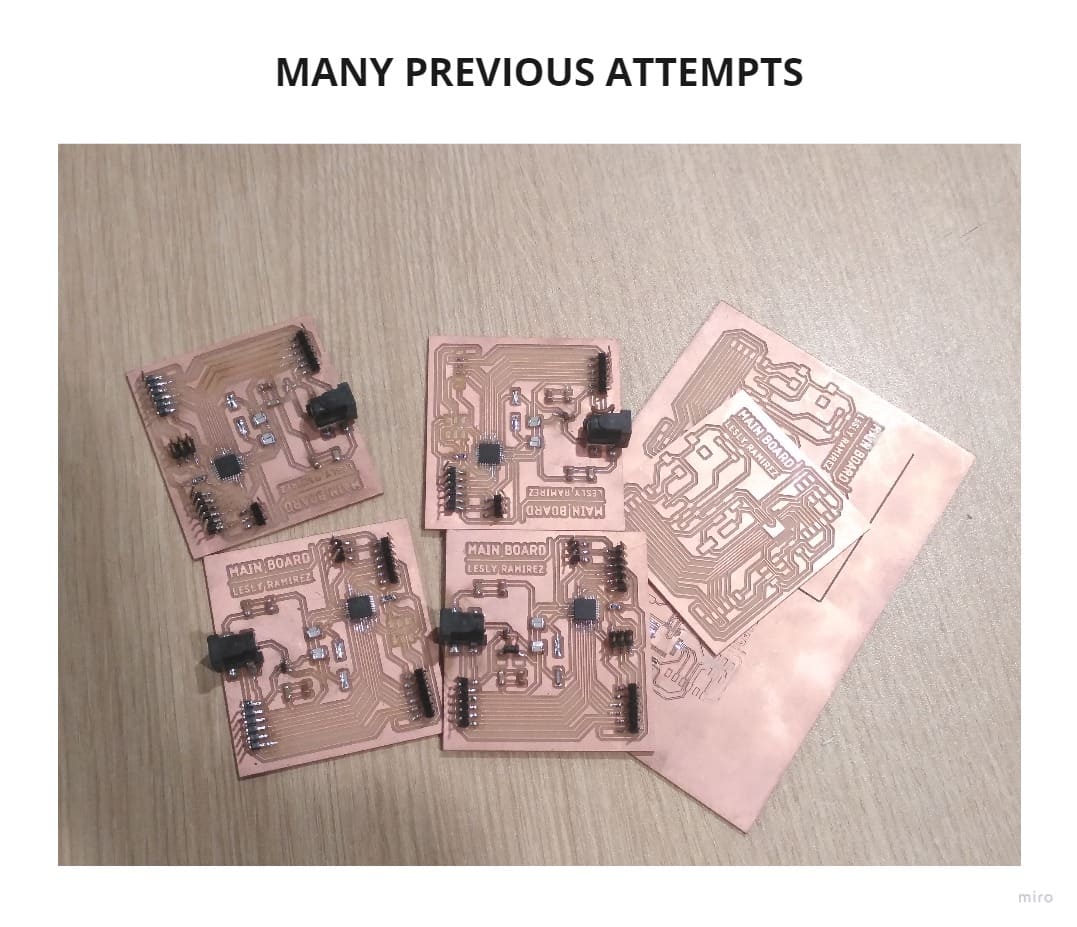
Another problem that arose was that every time I milled the board, the pads’ feet were lifted, so I had many errors, I made about 4 boards with the failed design until I learned that when cleaning the milling residues I must do it with too much delicacy. In addition, I used tweezers to get the tracks that were lifted back into place.
And the last problem that arose was that the board did not work after programming, so I had to modify the design several times, solder, mill and test. The mistake was that the POWER JACK CONNECTOR was wrong, I short circuited many times until I found the mistake when I separated the power supply board and the main design. You will see it in more detail in the “Programming” section.
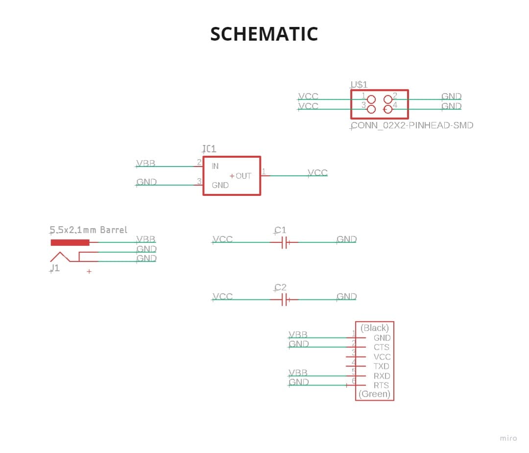
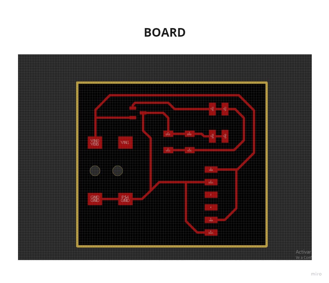
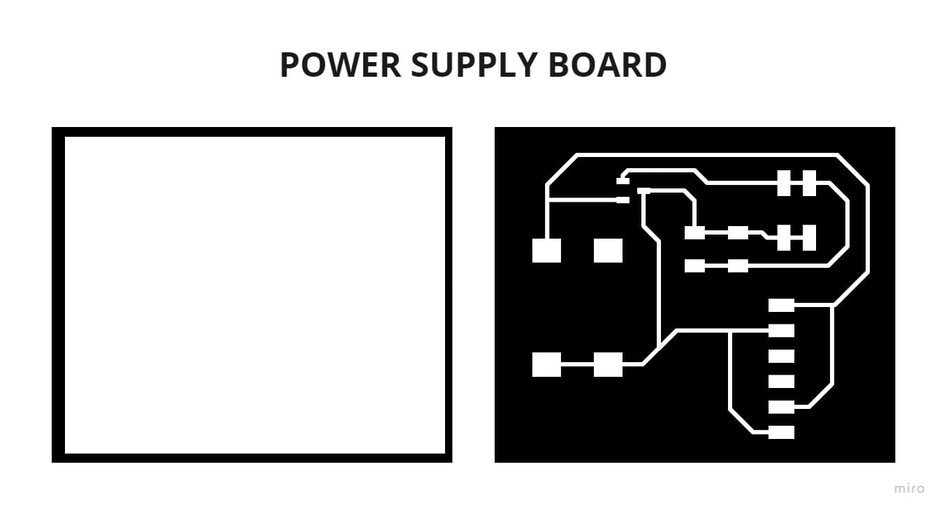
5.2 POWER SUPPLY BOARD
This board caused me problems since it was previously integrated in my main board, but I had to make it independent to verify with the multimeter if 12v and 5V were really coming out respectively.
If you use a POWER JACK CONNECTOR, I suggest you see my schematic design and board layout so you don’t make mistakes in the VCC and GND connections.
This is the last board I made and I connected it directly when I was putting together my final project, so that’s why I didn’t take an individual picture of the results, but you can see it in the programming section or also in the video I added.
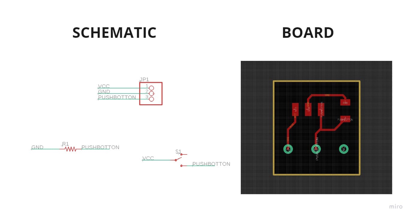
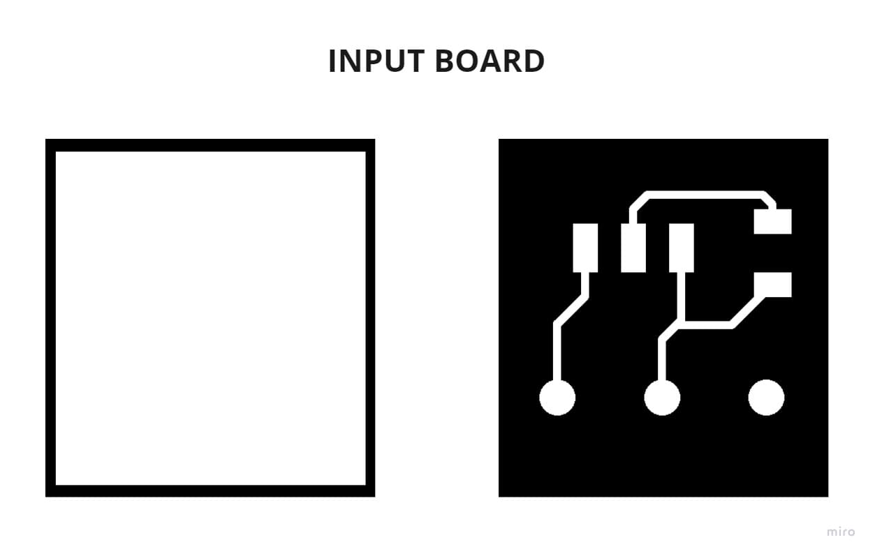
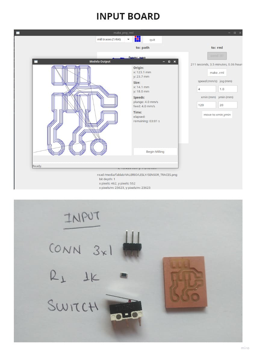
5.3 INPUTS
My Input board has only 3 components, withpins it connects to the main board (digital pin, VCC and GND), I had to make 3 equal boards because I had two limit switch sensors and a rocker switch, all of them had the same pin layout.
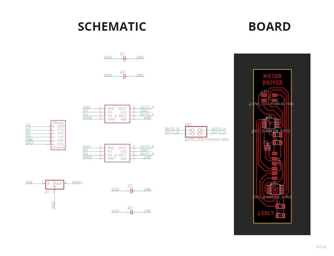
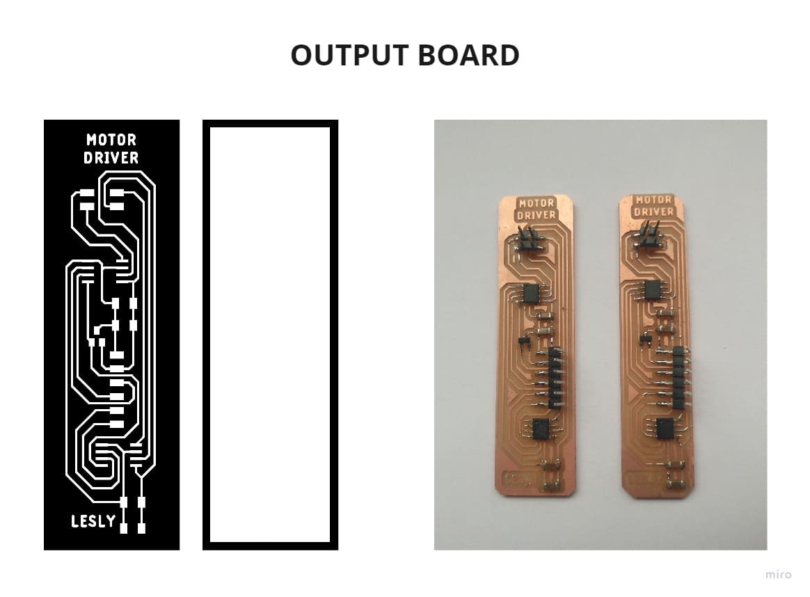
5.4 OUTPUT
This board contains few components and is connected by wires, I rely on my OUTPUT board of the week to be able to connect each wire properly, an error causes the motor to not work as it should.
I made 2 identical boards since I needed one for each motor.
6. PROGRAMMING AND TESTING
Due to the multiple sensors and orders, it was necessary to make the code based on functions, I explain in the following diagram how the orders would work in the INPUT (P, P1, P2) and OUTPUT (STEPPER MOTOR), making clear that all orders come out of the microcontroller.
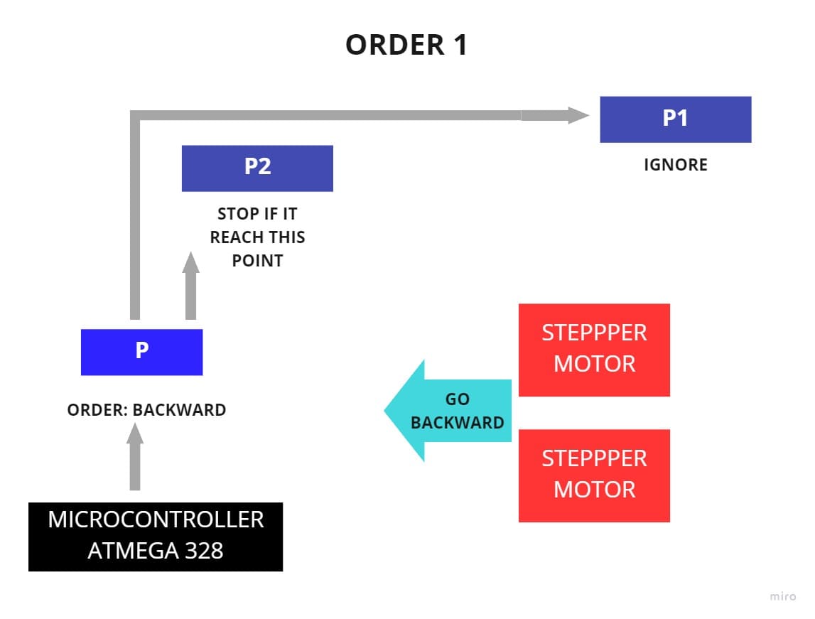
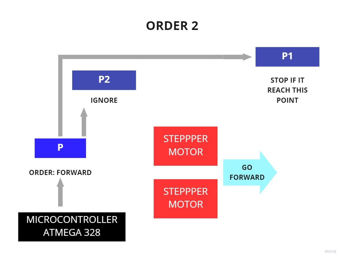
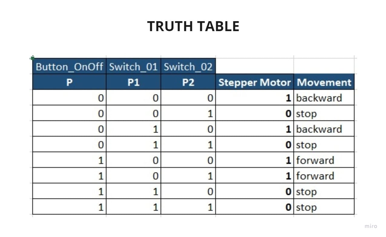
You can see the code below:
#include <Stepper.h>
#define button_OnOff 2
#define limitSwitch_01 3
#define limitSwitch_02 4
#define led 13
#define stepsPerRevolution 200

// variables will change:
int p0 = 0;         // variable for reading the pushbutton status
int p1 = 0;
int p2 = 0;

Stepper myStepperL(stepsPerRevolution, 9, 10, 11, 12);
Stepper myStepperR(stepsPerRevolution, 5, 6, 7, 8);

void setup() {
  // put your setup code here, to run once:
  Serial.begin(9600);
  pinMode(button_OnOff, INPUT);
  pinMode(limitSwitch_01, INPUT);
  pinMode(limitSwitch_02, INPUT);
  pinMode(led, OUTPUT);
  myStepperL.setSpeed(100);
  myStepperR.setSpeed(100);
}

void loop() {
  // put your main code here, to run repeatedly:
  p0 = digitalRead(button_OnOff);
  p1 = digitalRead(limitSwitch_01);
  p2 = digitalRead(limitSwitch_02);

  if(((p0==LOW)&&(p1==LOW)&&(p2==LOW))||((p0==LOW)&&(p1==HIGH)&&(p2==LOW))){
    digitalWrite(led, HIGH);
    myStepperL.step(1);
    myStepperR.step(1);
  }
  if(((p0==HIGH)&&(p1==LOW)&&(p2==LOW))||((p0==HIGH)&&(p1==LOW)&&(p2==HIGH))){
    digitalWrite(led, LOW);
    myStepperL.step(-1);
    myStepperR.step(-1);
   }
}
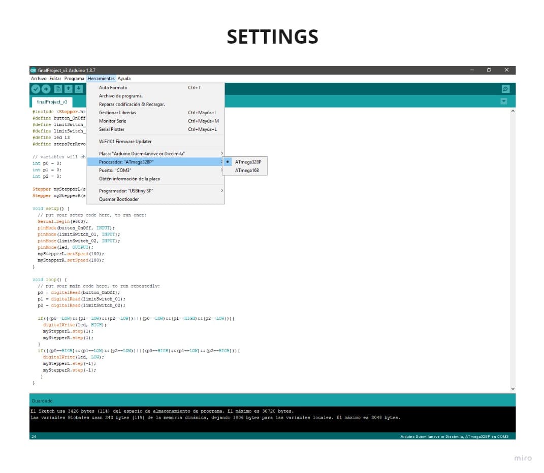
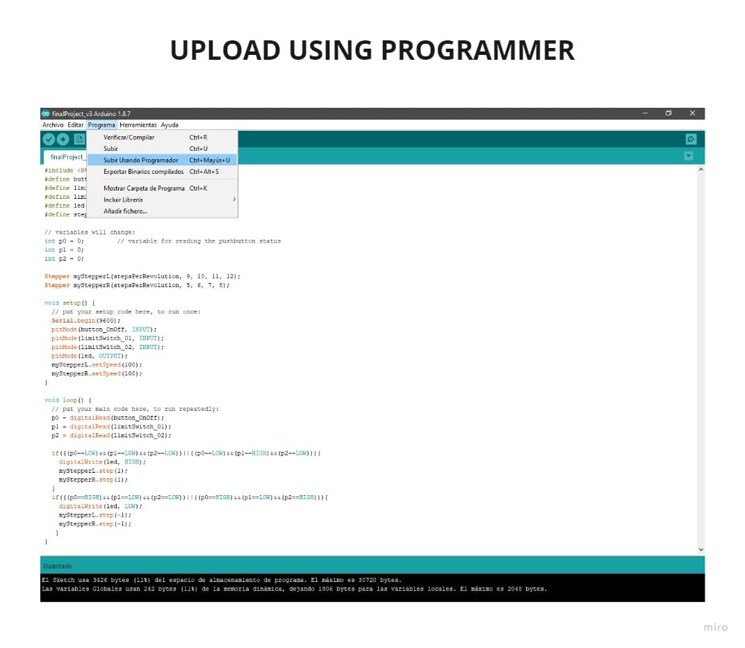
I had to take into account the configurations that you will see in the following pictures and program with the option “UPLOAD USING PROGRAMMER”:
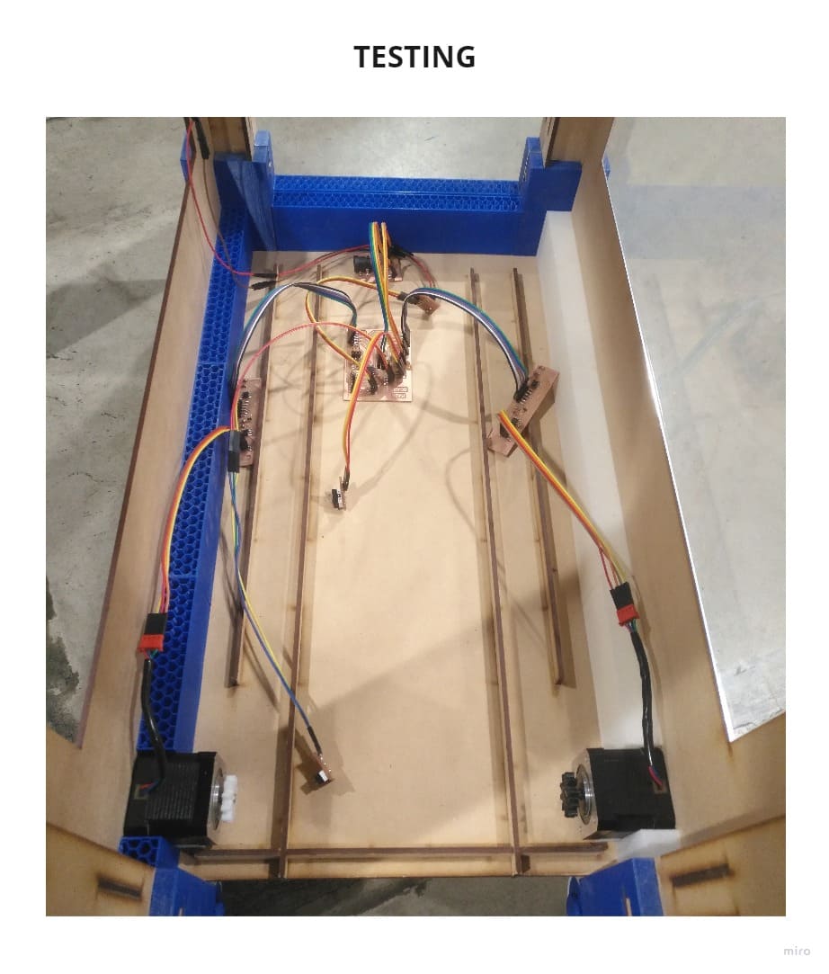
To test it, first all the components were placed and connected, the surprise is that when it turned on, it was slower than expected.
Then I placed the piece that has a zipper to be moved by the gear that is with the motors, and a motor was not moving, it was too strange, so we checked the wires and there were some that were not making contact, it was at that moment that I soldered again and it worked, it was even moving with the correct speed.
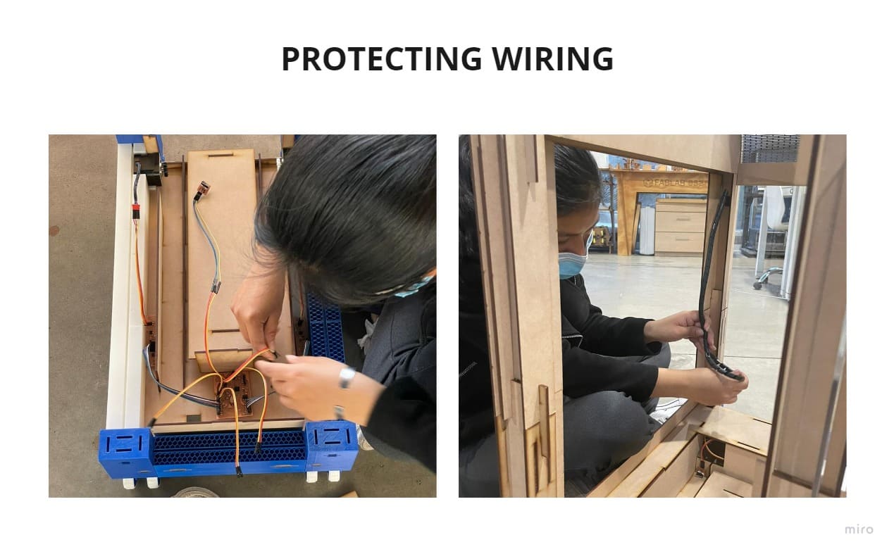
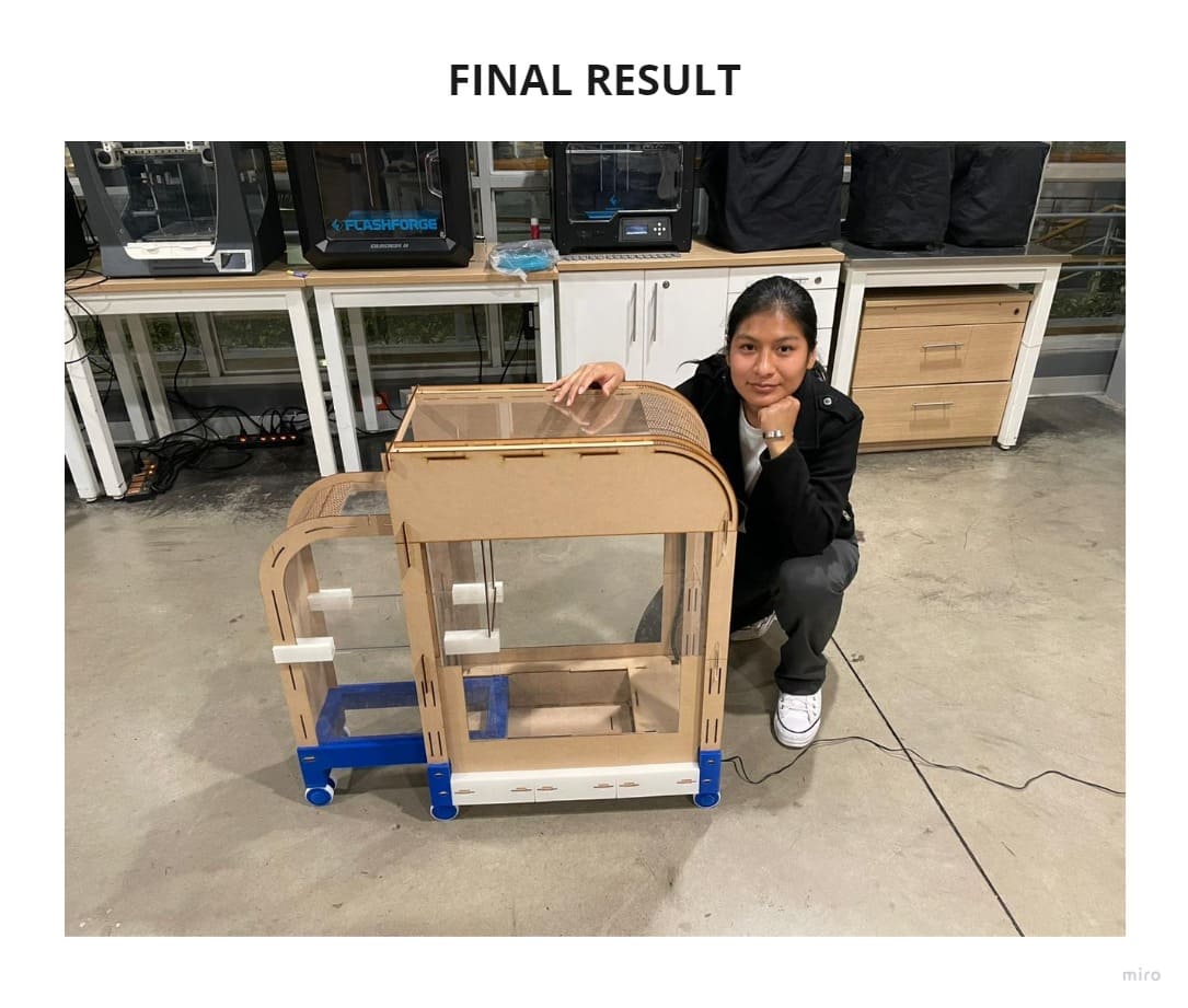
Finally I placed protection wires before closing the cover, you can see in the photo of the final result that there are no exposed wires, only the power supply cable is connected externally.
This was a big challenge, doing all my project with press-fit between the parts and without using screws, it has helped me to realize all the work behind a prototyping project, many times things don’t go right and you have to try again and again until you find the mistake and fix it. If you have an idea, don’t give up, keep going! You don’t know how far you can go if you don’t try.
7. LICENSE
LICENSE - LESLY RAMIREZ - COMMERCIAL FOLDING MODULE
8. BILL OF MATERIALS
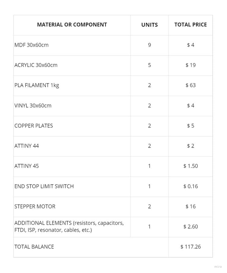
9. CONCLUSIONS
-
If you have doubts about the failures of your board after it has been programmed, it is possible that it is the connection to the power supply or a poorly soldered cable, you can make a separate board just for the power supply to see if the voltage that comes out is correct, so you will avoid burning your microcontroller or other components such as the regulator.
-
If something fails even though the test was done many times and everything had gone well before, maybe a wire is broken or some connection is wrong because that could generate the error, always check all connections.
-
There are many things that can be improved in the design, such as the position in which the power supply is connected or even adding more interior trays where the products can be left. I am going to develop this prototype into a more aesthetic one and with the lowest possible cost because I am passionate about creating this type of furniture, the difference is that now I know how I can develop them, how to approach from design to electronics and there is still a lot to learn, this is just the beginning.
-
I am very happy to have been part of the Fab Academy, it has helped me to develop different skills and learn to work from the simplest to the most complex, but most of all I learned not to give up and keep trying!