11. Output devices
Group assignment:
-
Measure the power consumption of an output device.
-
Document your work to the group work page and reflect on your individual page what you learned.
Individual assignment:
- Add an output device to a microcontroller board you’ve designed and program it to do something
1. INDIVIDUAL ASSIGNMENT
This week I had to add an output device and I chose to use a Stepper Motor, because I will use it for my final project.
DESIGN
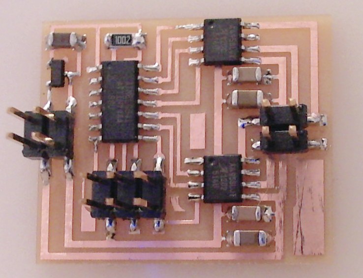
I have used the stepper motor called “Bipolar H-bridge” board as an example:
I used the EAGLE software, I was adding the components and joining as in the Electronic design week, these are the components I used:
UC_ATTINY44-SSU
R1206FAB : R1 - 10K
CAP_UNPOLARIZEDFAB : C1 - 1 uF
CAP_UNPOLARIZEDFAB : C2 - 1 uF
CAP_UNPOLARIZEDFAB : C3 - 10 uF
CAP_UNPOLARIZEDFAB : C4 - 1 uF
CAP_UNPOLARIZEDFAB : C5 - 10 uF
CONN_03x2_AVRISPSMD
PMIC_H-BRIDGE_A4953 ( 2 units)
CONN_02X2_PINHEAD-SMD (2 units)
VR_REGULATOR-SOT23SOT23
Something I noticed is that there was not the additional component called FTDI that I had already seen in previous boards, in the programming section we will see how the lack of this component will be solved.
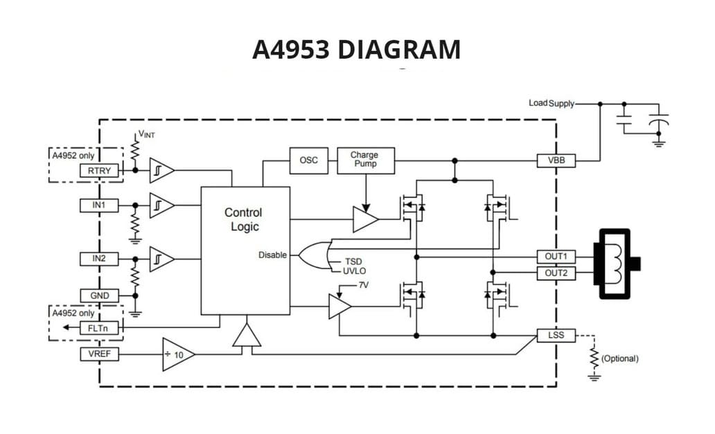
You can also see a new component, in the library it can be found as PMIC_H-BRIDGE_A4953 or also known as Full-Bridge Motor Drivers, these help to control the DC motors, you can get more information in the following link: A4953 DATASHEET
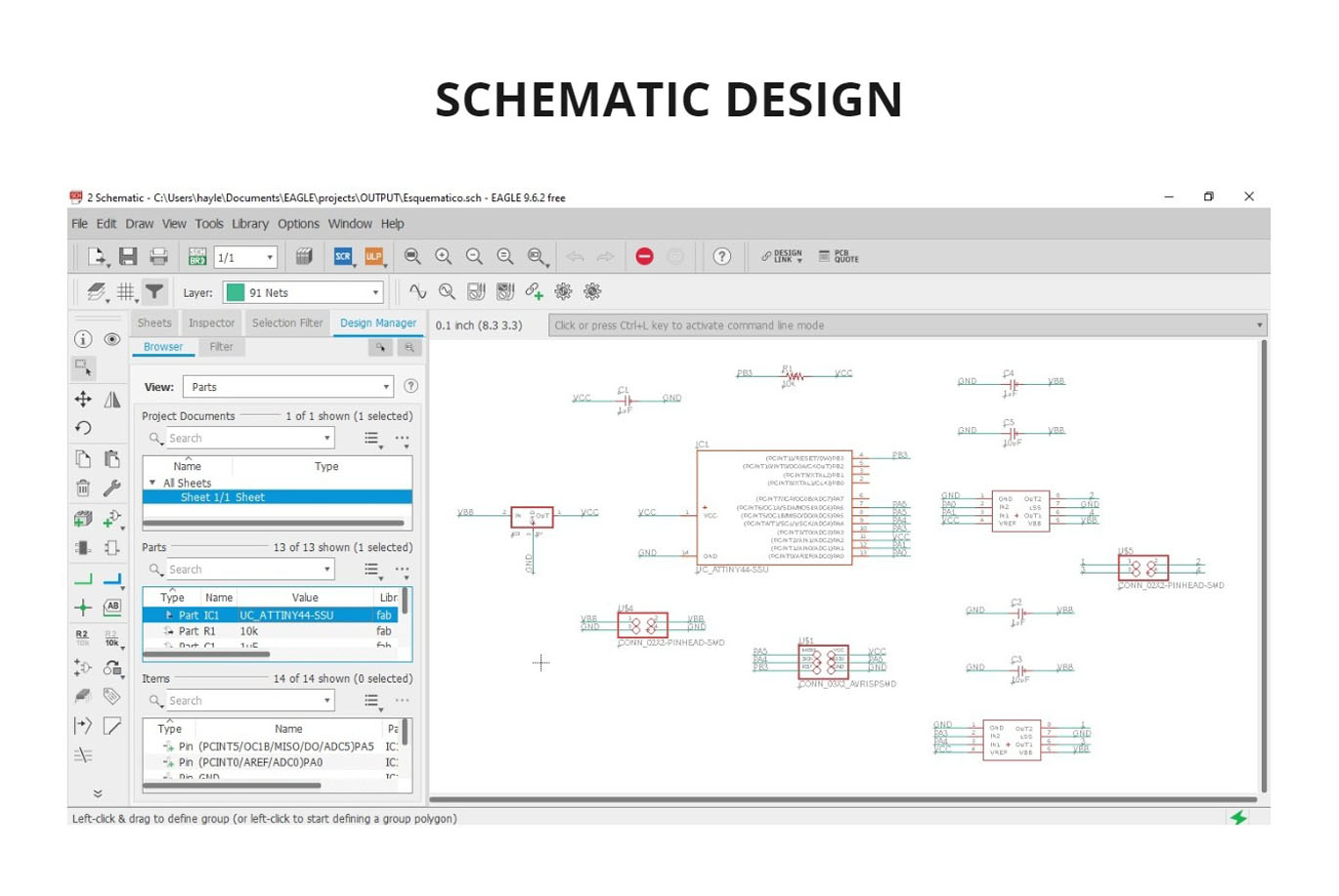
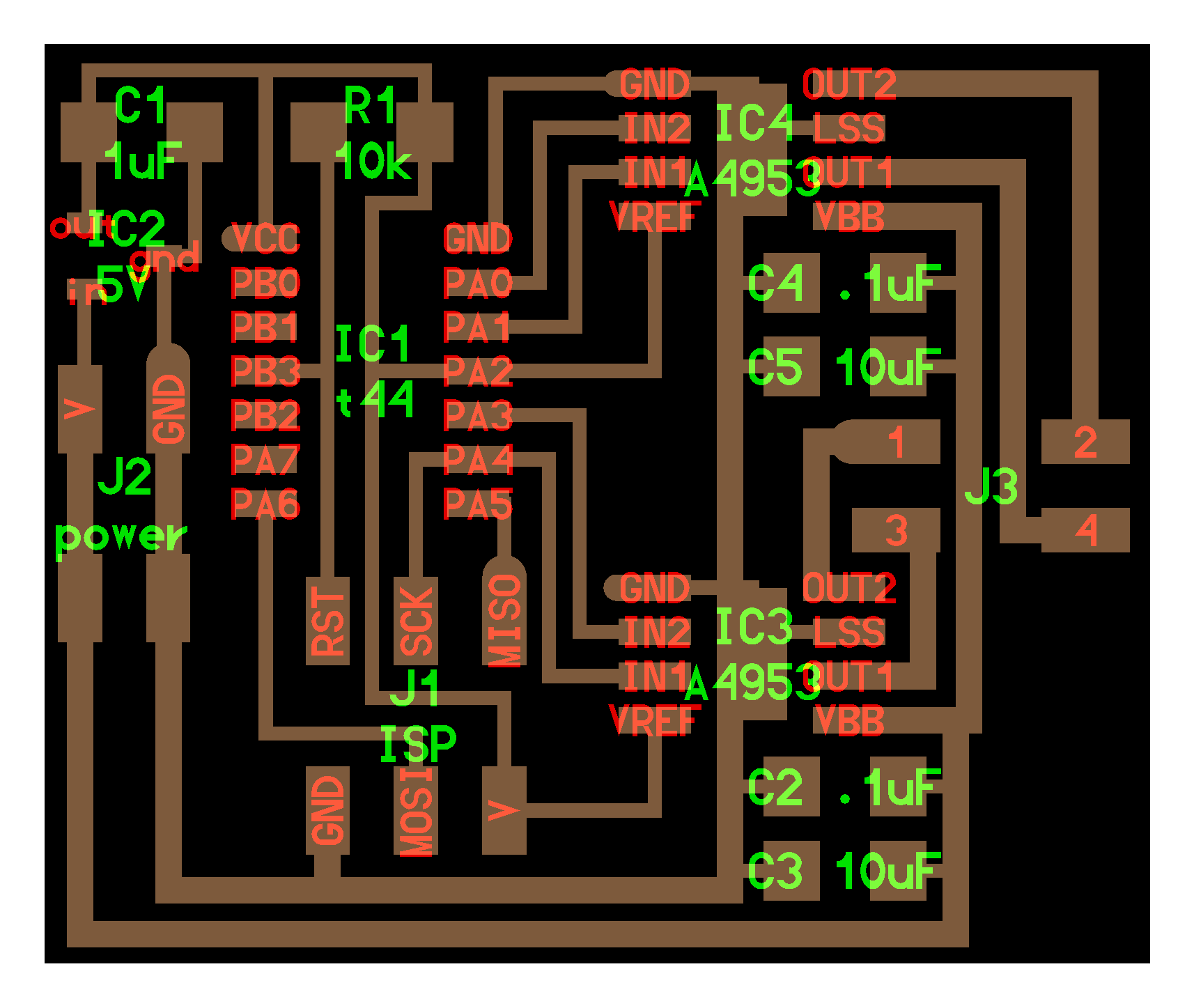
I developed my schematic design making the connections, indicating name and value to the components as in Electronic Design week but with different components.
This is the schematic design that I made:
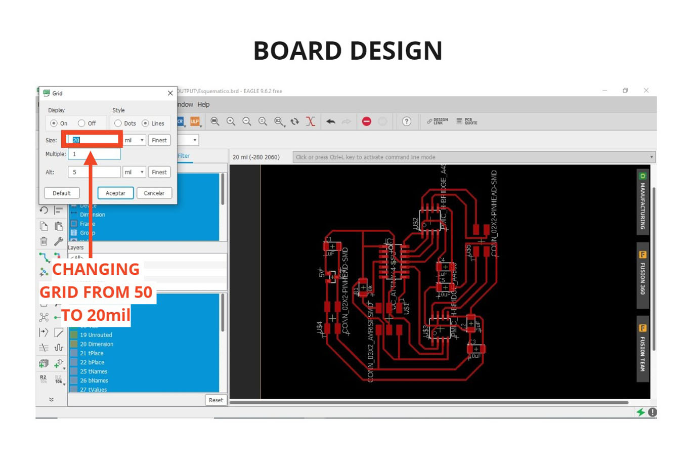
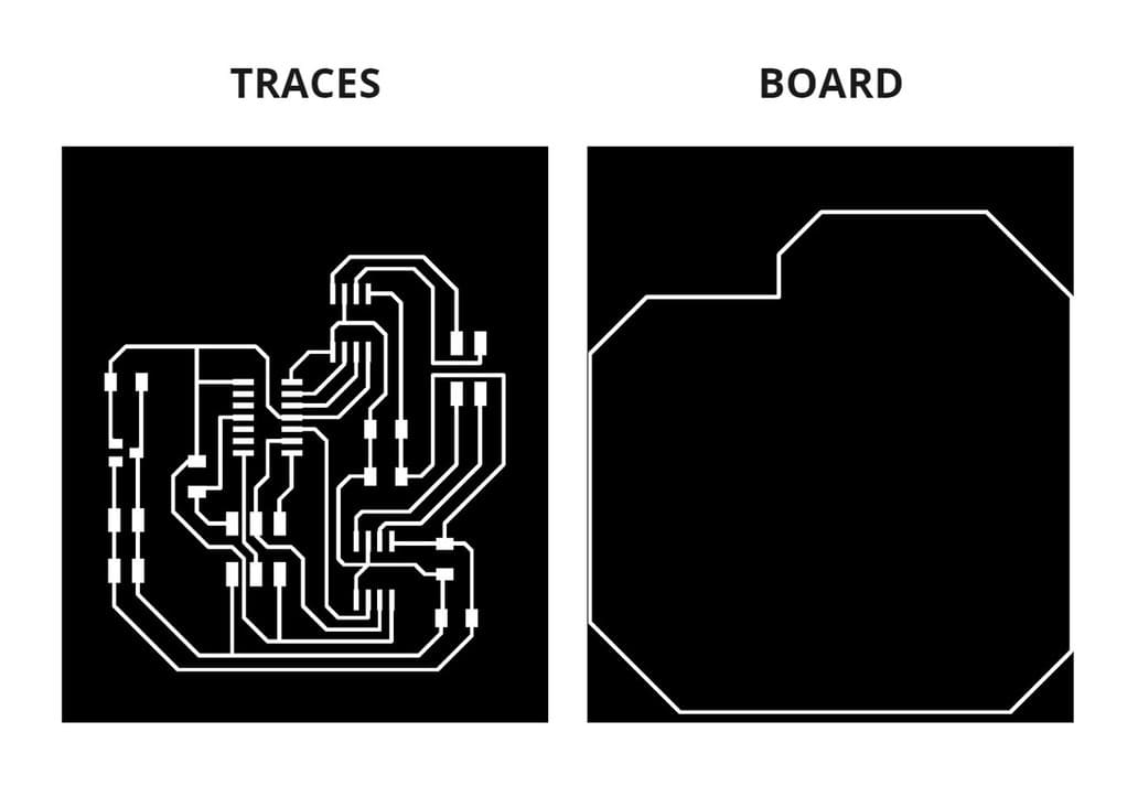
Then I started to make the board design and trace the components with the ROUTE AIRWIRE tool.
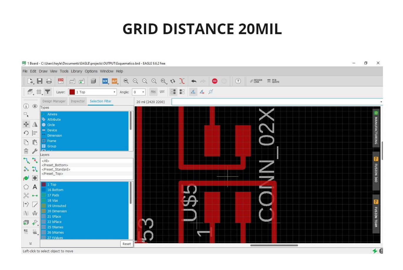
Something that limited me was not being able to pass more than one trace next to another in the middle of components, this was because my GRID tool was in size 50mil, I had to change it to 20mil. This allowed me to have adequate space for more than one wire to pass through without colliding with other wires, it helped me to solve the problem and connect all my wires.
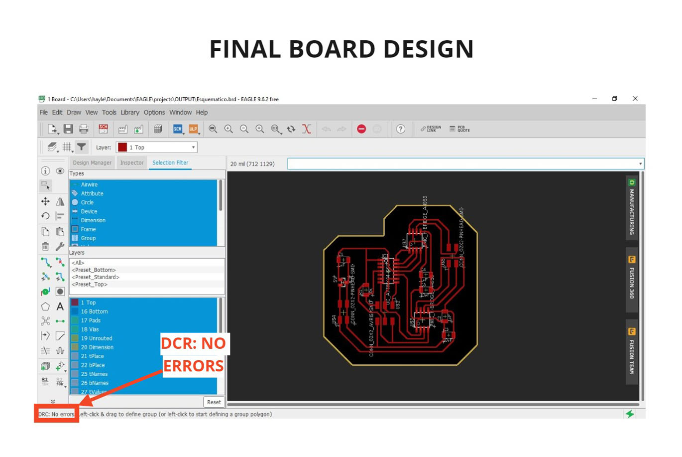
One of the things that surprised me is that when I applied the DESIGN RULES, I didn’t see any little square indicating the errors, which had happened on my previous board, I didn’t know if it was right or wrong. I consulted my instructor and he told me that if in the lower left part I could see the phrase DCR: NO ERRRORS, it meant that everything was well connected, it came out the first time and I got excited 😅.
Finally, I drew the borders and then deactivated the layers to export separately the traces and the border of the board. I followed the same process I did in the electronic design assignment, you can review it in the following link: Electronic design week
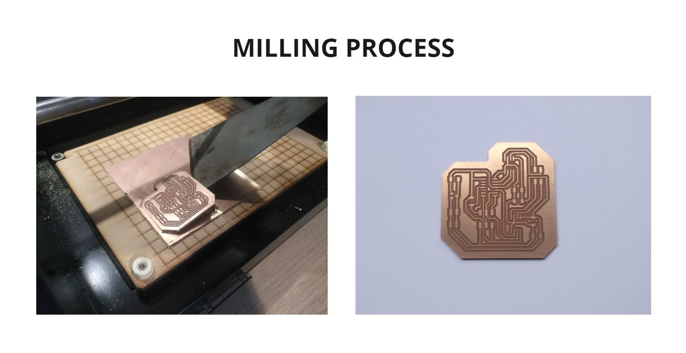
FABRICATION
For fabrication I followed the same steps for using the Roland Modela MDX-20 milling machine on Electronic production’s week. The milling cutters used are the same, 1/64'' and 1/32'', as well as cutting and milling configurations.
You can see it in the following link: Milling Machine configuration
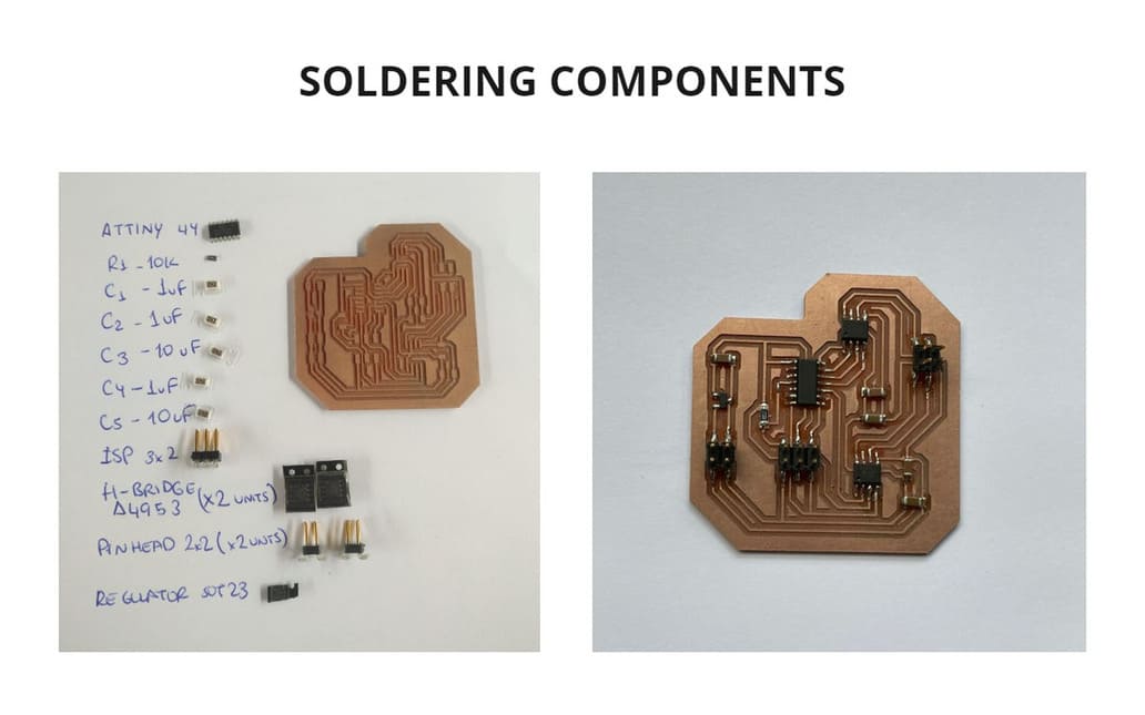
SOLDERING COMPONENTS
Finally I soldered the components, remember to keep in mind the position of the Attiny44 and the Full-Bridge Motor Drivers, you can identify a circle in one of the corners of these 3 components and place it accordingly to your SCHEMATIC DESIGN(You can find white circles on your schematic)
The Attiny has the circle near the pin that connects to VCC, while the Full-Bridge Motor Drivers have the circle near the pin that connects to GND.
PROGRAMMING
The board had no FTDI input, which is necessary to program in ARDUINO IDE, so I worked with the LINUX TERMINAL, so the ISP input had double use, it was connected to the programmer but also had a connection to the PC, instead of using two ports, only one was used. I used Neil’s code as an example and make modifications to change certain ranges and see the results.
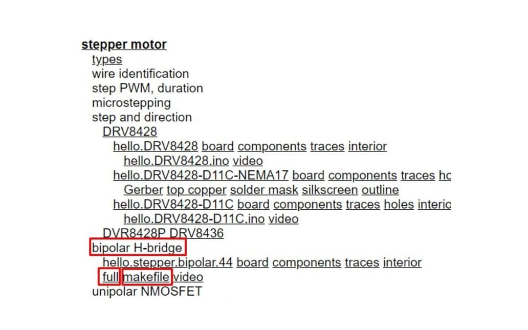
Now we are going to program, for this we must go to Out Devices classes and follow the steps below:
- I am working with a
STEPPER MOTOR, I go to theBIPOLAR H-BRIDGEsection, we will need to download theFULLandMAKEFILEfiles. These are files that will help us to program our board, we can modify certain parameters to obtain different results.
-
Then, I saved the downloaded files in a folder:
hello.stepper.bipolar.44.full.makeandhello.stepper.bipolar.44.full.c. According to the TUTORIAL OF EMBEDDED PROGRAMMING , I had to rename the filehello.stepper.bipolar.44.full.maketoMakefile. -
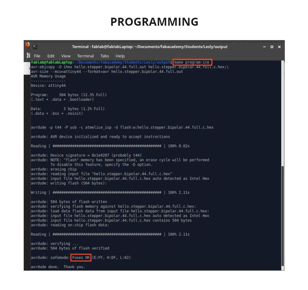
I connected the ISP of the board to the programmer, which at the same time was connected to the PC. Then I used the LINUX TERMINAL to enter the folder where these files were located, I used the commands
ls, cdandlsusb, it is very similar to what we do when we use Gitbash. -
Then I put
make program-iceand it seemed to have programmed, but at the end I got this message:ERROR.
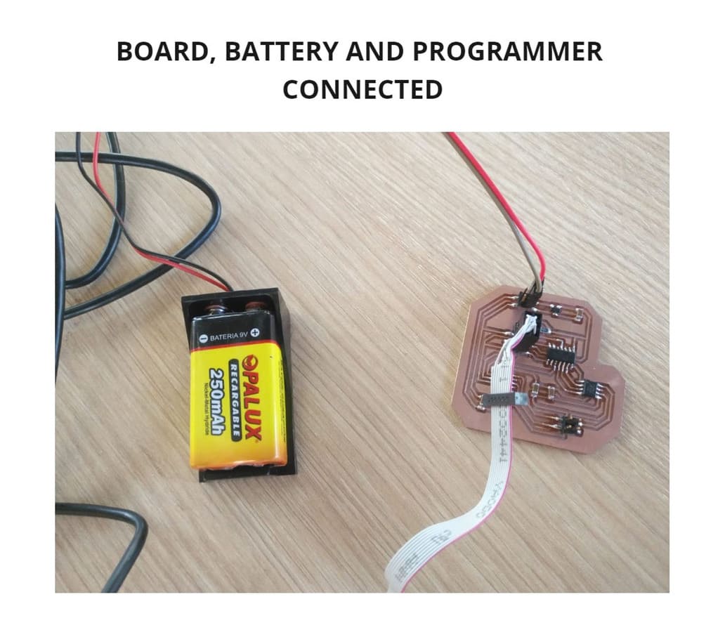
WHY THE MESSAGE: ERROR? There was nothing wrong with the design or the soldering, the problem was that the board needed to be connected to some power supply, this time I used a battery and repeated the make program-ice command again and it managed to record!
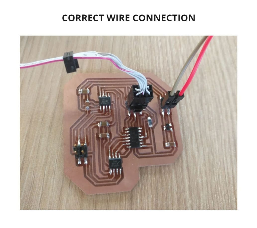
I had to take into account the following considerations:
-
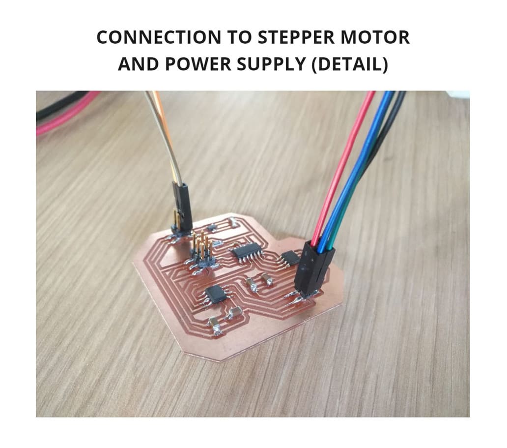
Do not confuse the wires, remember the position of the components, black wire goes to GND (Negative) while red wire connects to the other pinhead (Positive).
-
Use jumper wires if necessary, I used them to connect the battery to the board.
-
The regulator helps to ensure that the voltage reaching the ATTINY44 microcontolator does not exceed a limit, in this case 5V. To prevent it from burning out if it receives more voltage.
-
In the case of A4953 motor drivers, the normal amount of voltage is supplied, since there are no regulators in the middle of this connection (You can check the board design to confirm this).
-
I used the atmel ice programmer, that’s why the code I use to program says
make program-ice, it’s possible to use other programmers, you can see them here: Makefile
These details can be seen in the following photos:
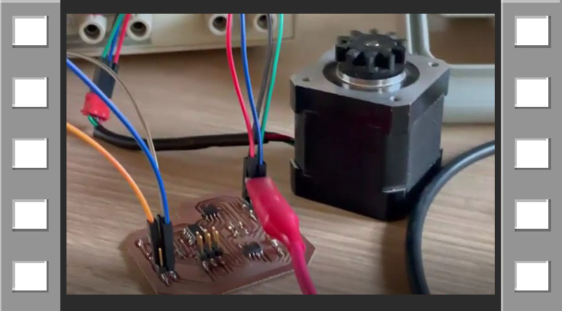
TESTING
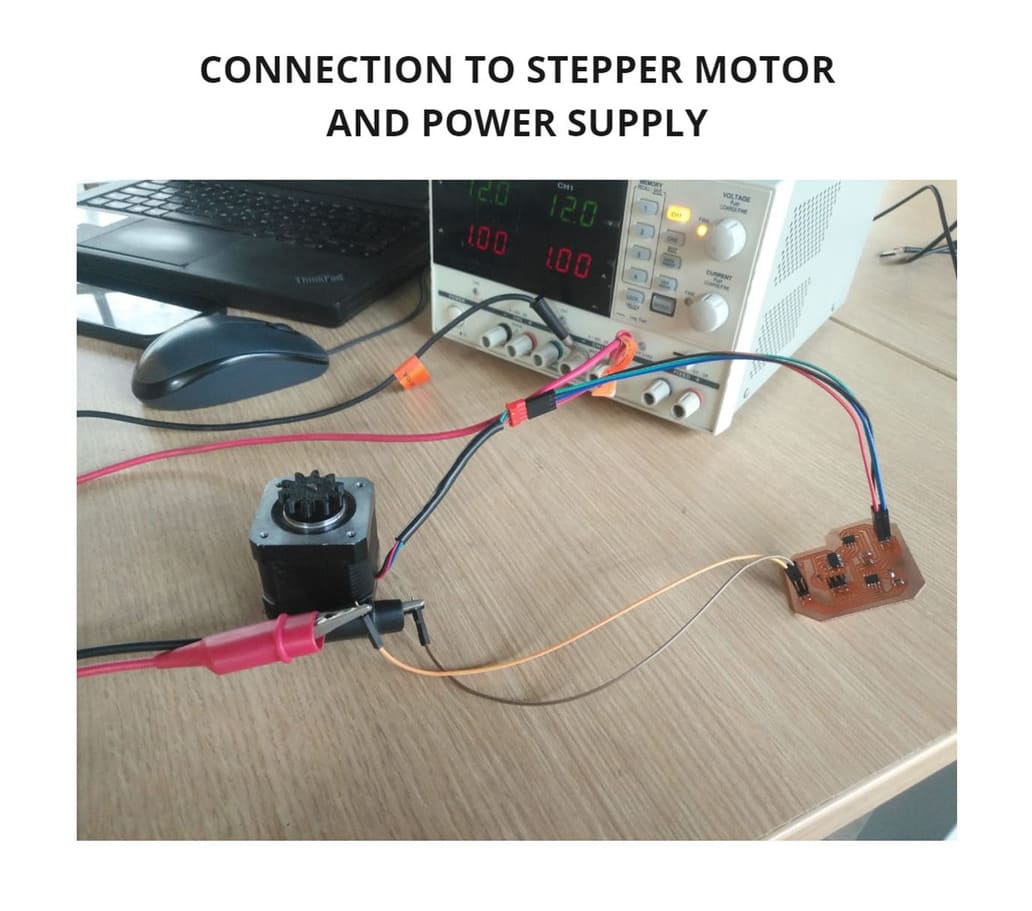
After programming, the programmer is disconnected. Only the power supply (in this case the battery) and the motor must be connected to the board.
Something unexpected happened, the motor spun for a few seconds and then stopped.
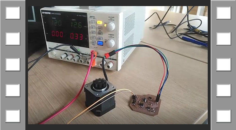
WHAT HAPPENED? The motor needed more power, the battery wasn’t enough, so I connected it to another power supply, I used the GW Instek GPD-3303, this is a DC Power Supply.
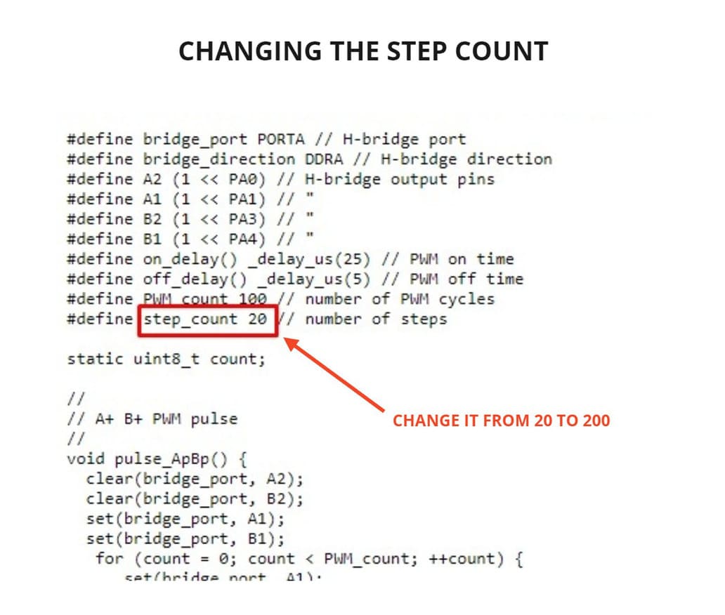
Finally the motor turned, it moved clockwise and then counterclockwise, as indicated by Neil’s example code. To see more difference, I changed a part of the code, the stepper count from 20 to 200 en the file FULL, I downloaded it and programmed the board again.
Then it was supposed to turn more, but it didn’t, something was wrong…
After a lot of thinking and testing, I had to investigate the details of the stepper motor connections and the pins that were connected to the A4953 MOTOR DRIVERS. I checked the datasheet of the motor drivers to know the correct connection of their pins with the stepper motor wires.
This website help me a lot , where I found the Stepper motor wiring connection, you can see the diagrams in the following images that I used as a guide:
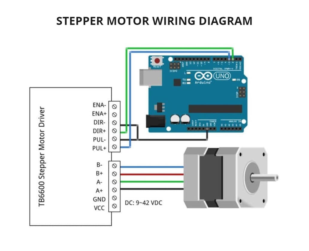
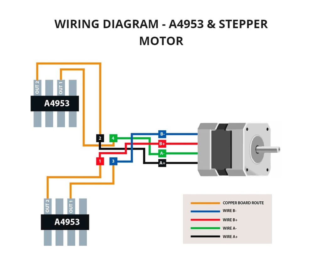
Based on this, I made my own diagram to know which pin to connect to.
Finally it worked! the wires had been connected wrong and when I changed the position, it worked perfectly. You will see the diagram I made of the Stepper motor and A4953, more photos and video below:
VIDEO TEST 1

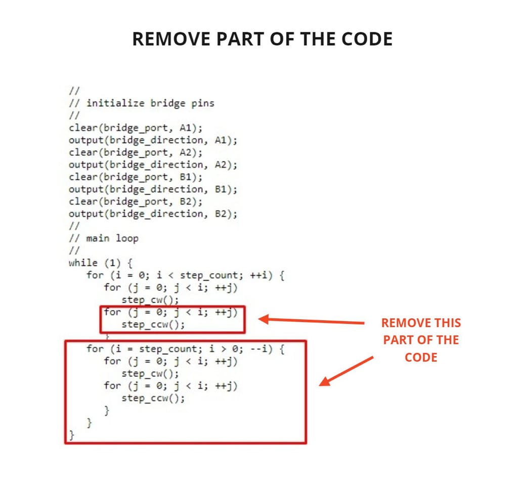
Also, if you want the motor to spin continuously in the same direction, you can delete part of the original code and reprogram it.
WHY? This part of the code makes it rotate clockwise and counterclockwise, by deleting it, it will rotate in one direction only.
This will be the result:
VIDEO TEST 2

2. GROUP ASSIGNMENT
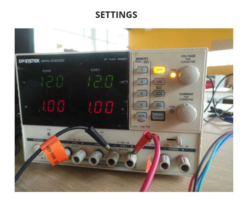
For the group assignment, I used the same board that I had done in my individual assignment. To measure the power consumption, I used the DC Power Supply GW Instek GPD-3303, you can see more detail in the following link:
In order to obtain the proper power consumption for the board, I first checked the datasheet of the stepper motor, Attiny44 and the A4953 motor controller. I concluded that 12V(Voltage) and 1A(Amps) was adequate.
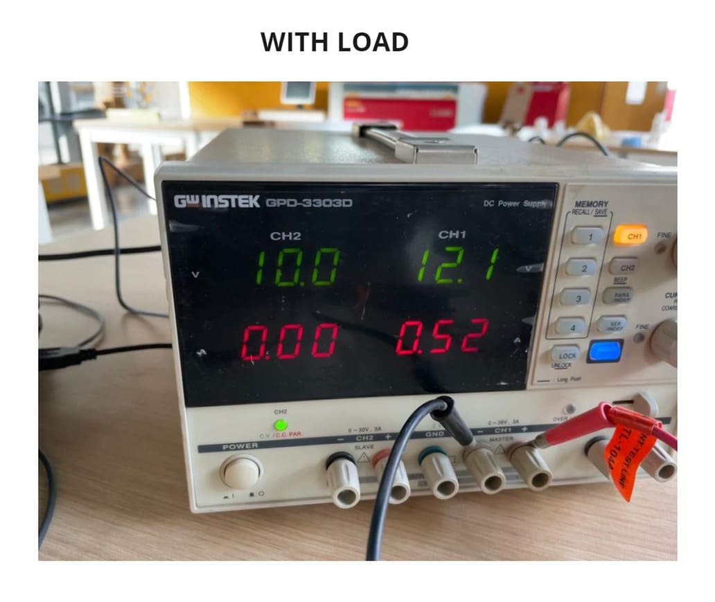
So, first I set the DC Power Supply values to 12V and 1A, pressed the OUTPUT button, this made the motor start and turn, but the values were constantly changing, the amperage was reduced by about half, the average values were 12.1V and 0.52A, I called this the WITH LOAD state, because the motor was connected and running while measuring.
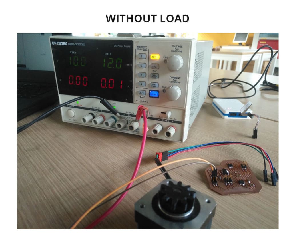
Then I disconnected the motor from the board to measure the value WITHOUT LOAD, this means that the motor was not going to interfere and only the power consumption of the microcontroller would be measured, the values were 12V and 0.01A.
To know the power consumption of each state, I have applied the formula P=VxA, this means that by multiplying the voltage x amperage, I will obtain the power consumption, represented by WATTS (W).
You can see the result of power consumption in each state below:
POWER SETTINGS:

P = 12V x 1A
P =  12W


WITH LOAD:

P = 12.1V x 0.52A
P = 6.292W


WITHOUT LOAD:

P = 12V x 0.01A
P = 0.12W
3. CONCLUSIONS
-
Always check the datasheet of the components you are using, whether they are microcontrollers, drivers, etc. This will help you to place them correctly and make the right connections.
-
Programming with Linux is very interesting, there is more compatibility for certain things like programming software.
-
Do not exceed the voltage and amperage limits of your components, if that happens, they could burn out.
-
DC Power Supply is very useful and necessary because you can regulate how much amperage and voltage for your project.
-
Being able to interpret the programming code will help you modify the parameters you need to obtain different results or create your own code using it as a guide.
-
Power consumption varies depending on the components you have, for example having a regulator changes the results.
-
If the parameters of your code are not too noticeable to see the faults, change them and see if there is a difference, if everything remains the same, you should check the connections.