14. Networking and communications
Group assignment:
- Send a message between two projects.
Individual assignment:
- Design, build, and connect wired or wireless node(s) with network or bus addresses.
1. INDIVIDUAL ASSIGNMENT
I decided to make a wired project, I used BRIDGE and NODE with ATTINY 45.
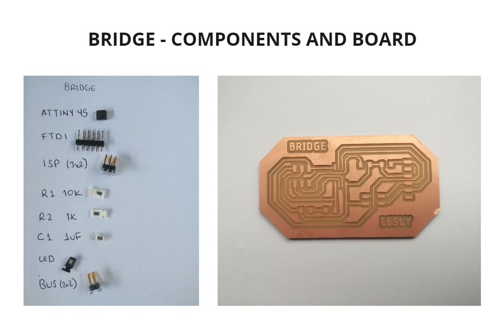
BRIDGE
This is the BRIDGE that I used as a guide:
DESIGN
I performed the same steps and recommendations to create my board, as in the electronic design week. You can see the step-by-step design of a board, tips and recommendations here: Electronic Design week:
-
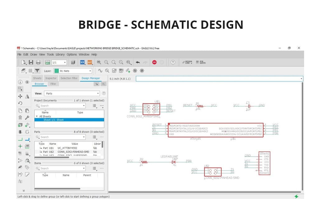
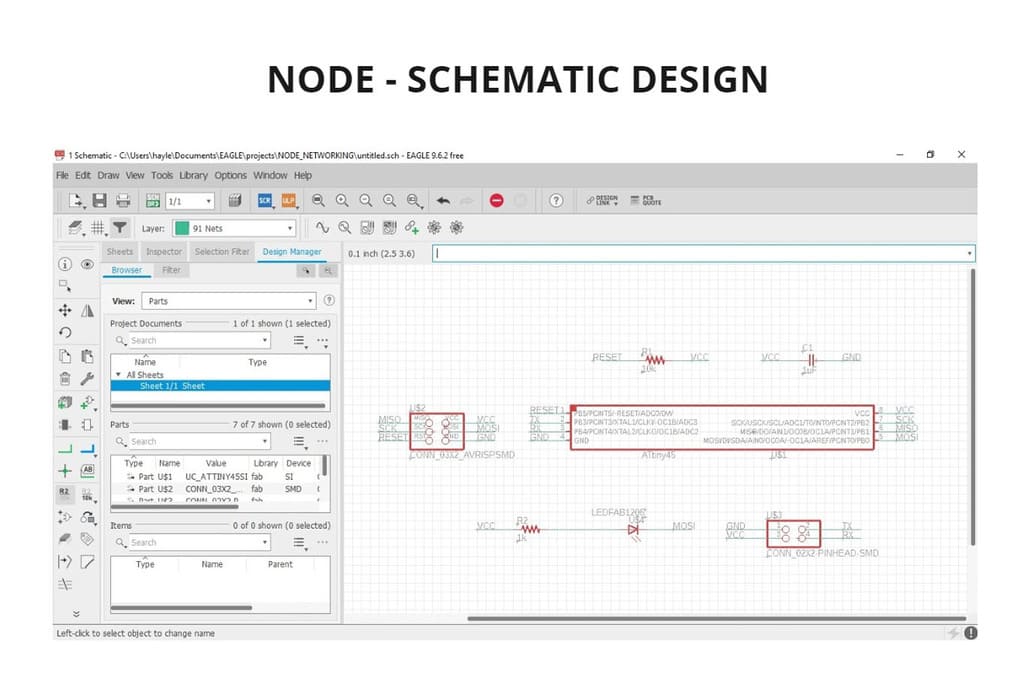
I developed my schematic design making the connections, indicating name and value to the components in EAGLE software.
-
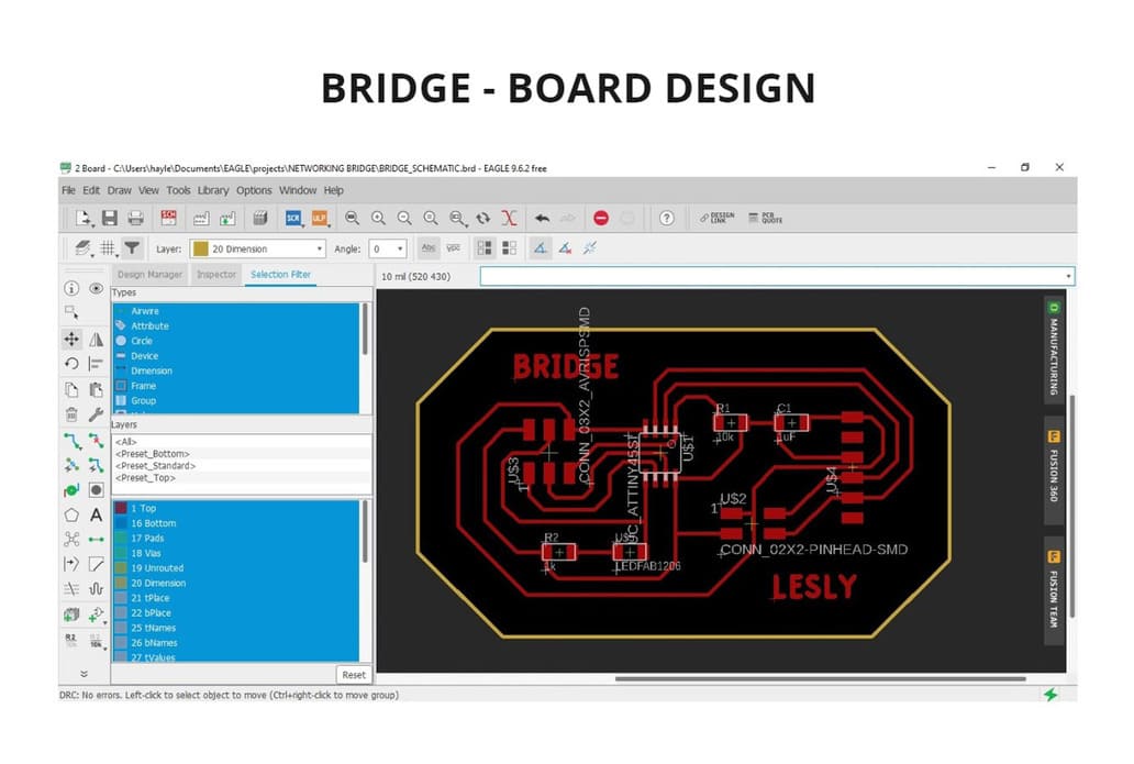
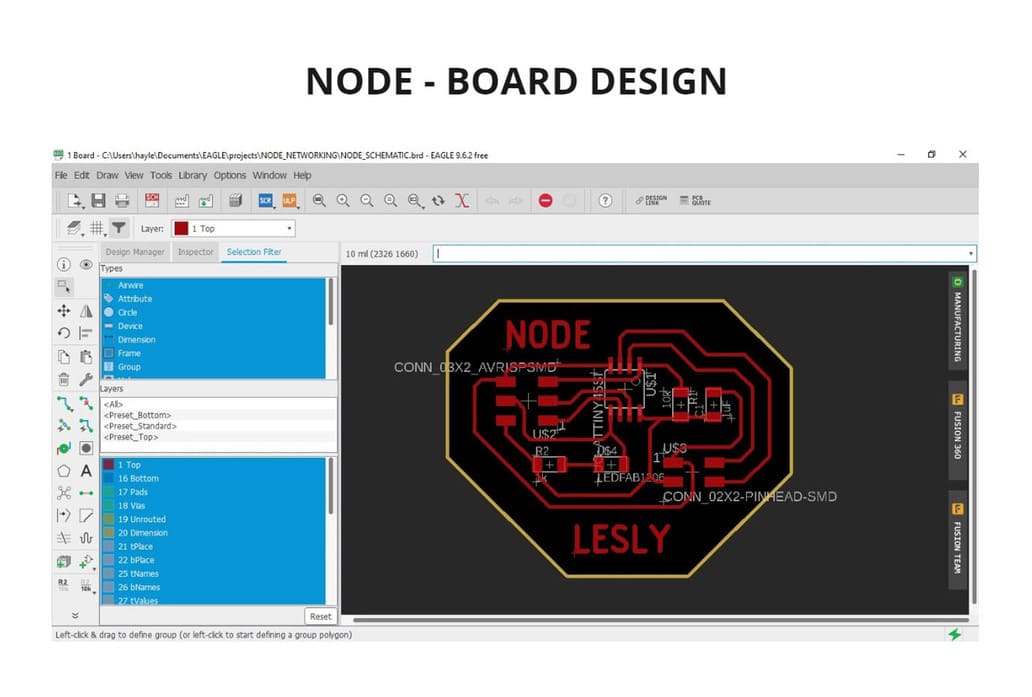
I followed the same steps and recommendations to generate the final board design taking into account the connections and
DESIGN RULES. -
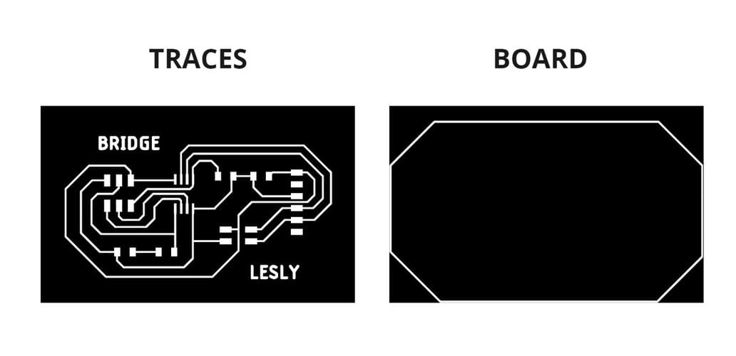
I then exported the exterior and the strokes as
BOARD and TRACESin .PNG format.
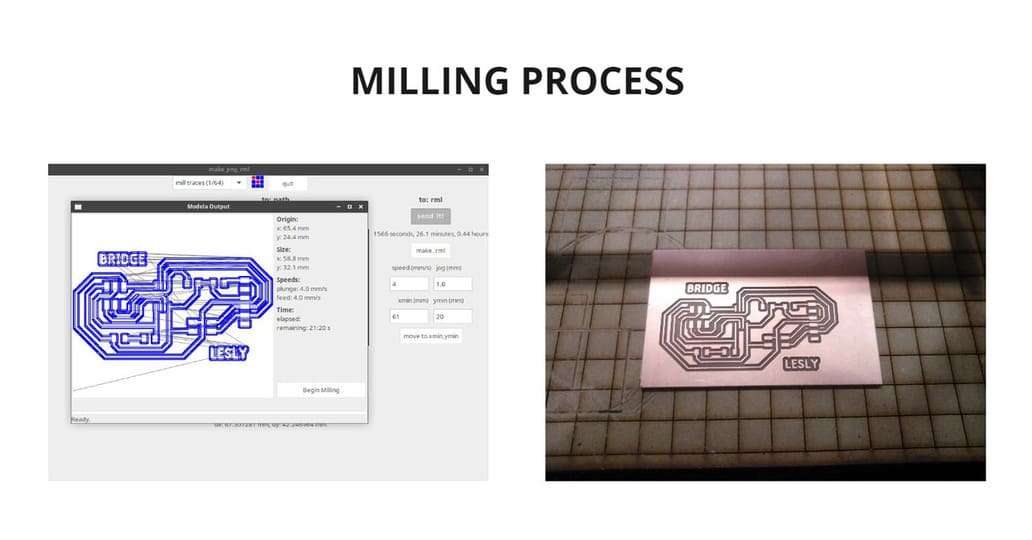
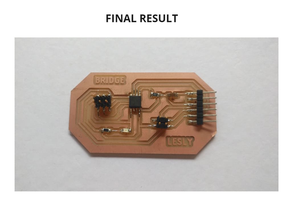
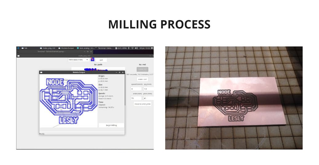
FABRICATION
For fabrication I followed the same steps for using the Roland Modela MDX-20 milling machine on Electronic production’s week. The milling cutters used are the same, 1/64'' and 1/32'', as well as cutting and milling configurations.
You can see it in the following link: Milling Machine configuration
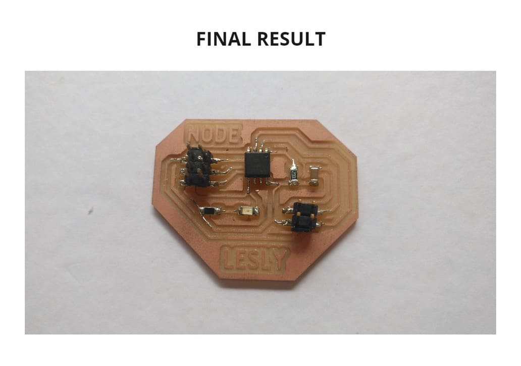
SOLDERING COMPONENTS
I soldered the components with tin and now I did it even faster as I have made several boards for previous assignments.
You can join the ends of a wire and adhere them to the board using tin, to give continuity to the connection, as I did in Electronics production week and even add silicone reinforcement as I did in Electronics design week
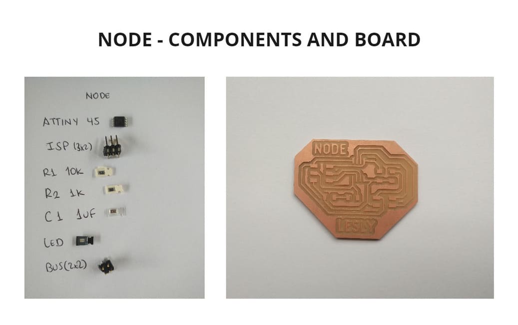
NODE
This is the NODE that I used as a guide:
I followed the same steps to create my board for the NODE, just as I did for BRIDGE, with a different shape and adding the name NODE to avoid confusion.
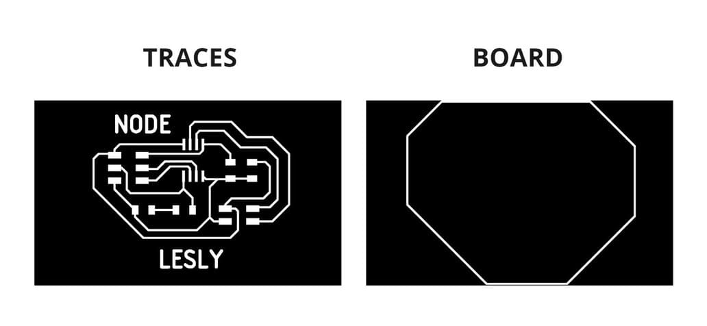
You can clearly see that there are differences in each board design, I did it that way so as not to confuse them and as an extra I added their names as BRIDGE and NODE.
Another difference you must take into account is that the BRIDGE has FTDI while the other one does not.
PROGRAMMING
For programming I downloaded the files hello.button.45.c and makefile that belonged to the Wired Attiny 45
I saved both files in one folder and renamed the file hello.button.45.make to Makefile, as in the Output Devices assignment
I used the programmer that I had made at Electronics Production week
There were many errors when I tried to program it for the first time, so I read the documentation from Babken Chugaszyan to correct these errors.
-
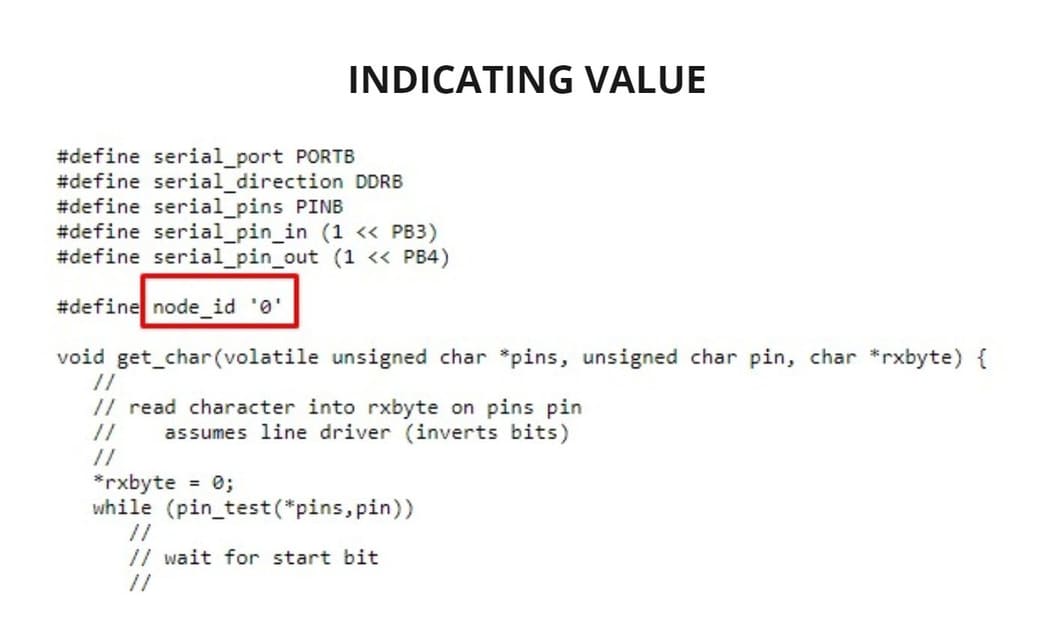
First, this is the code: hello.bus.45.c, you can modify it and re-download it as many times as you need.
-
The value after the
node_id, in this case is0, this is the value that the board led will respond to. In this case I will not modify it since I want the0to be the value ofBRIDGE. -
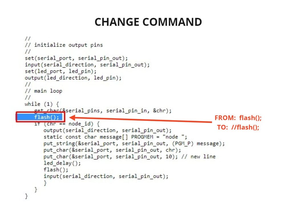
Then, changes from
flash();to//flash();, this will become a comment and will stop working as a command. This commandflash();is the one that makes the lights turn on at the same time, but I want the lights to respond to the value given to them. -
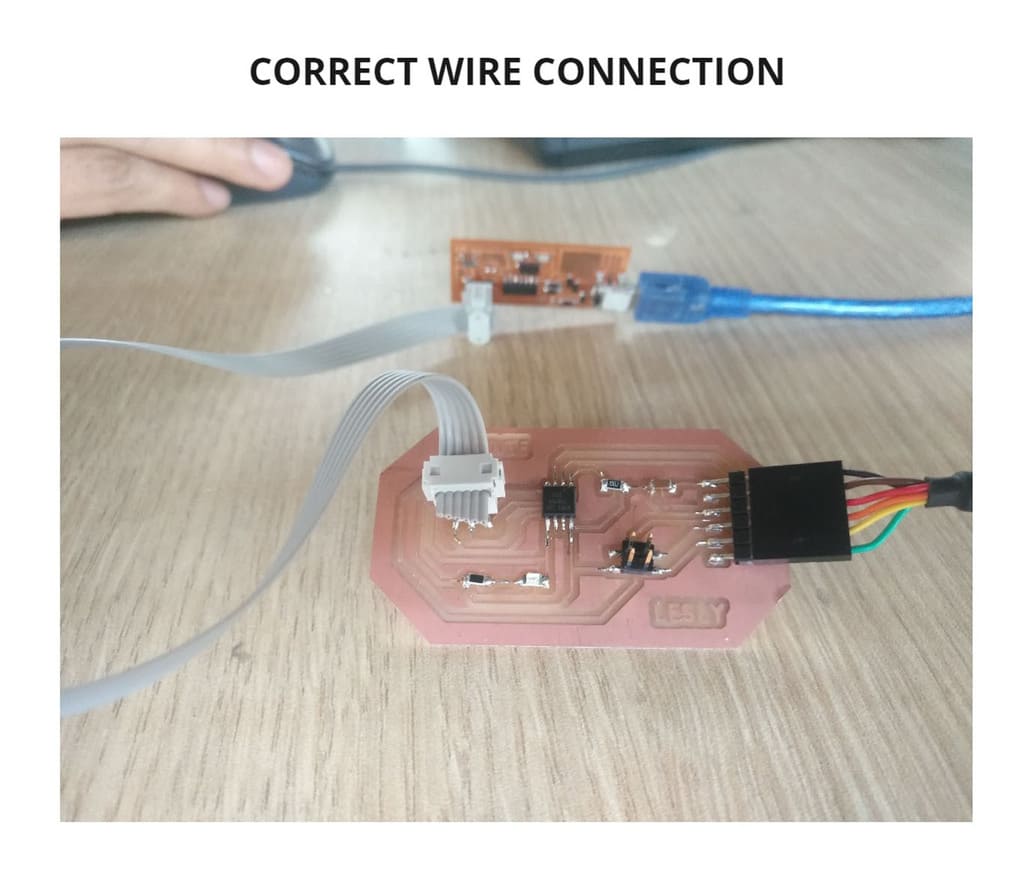
Download the code with these changes made, connect the programmer to the
ISPinput and theFTDIto the computer. -
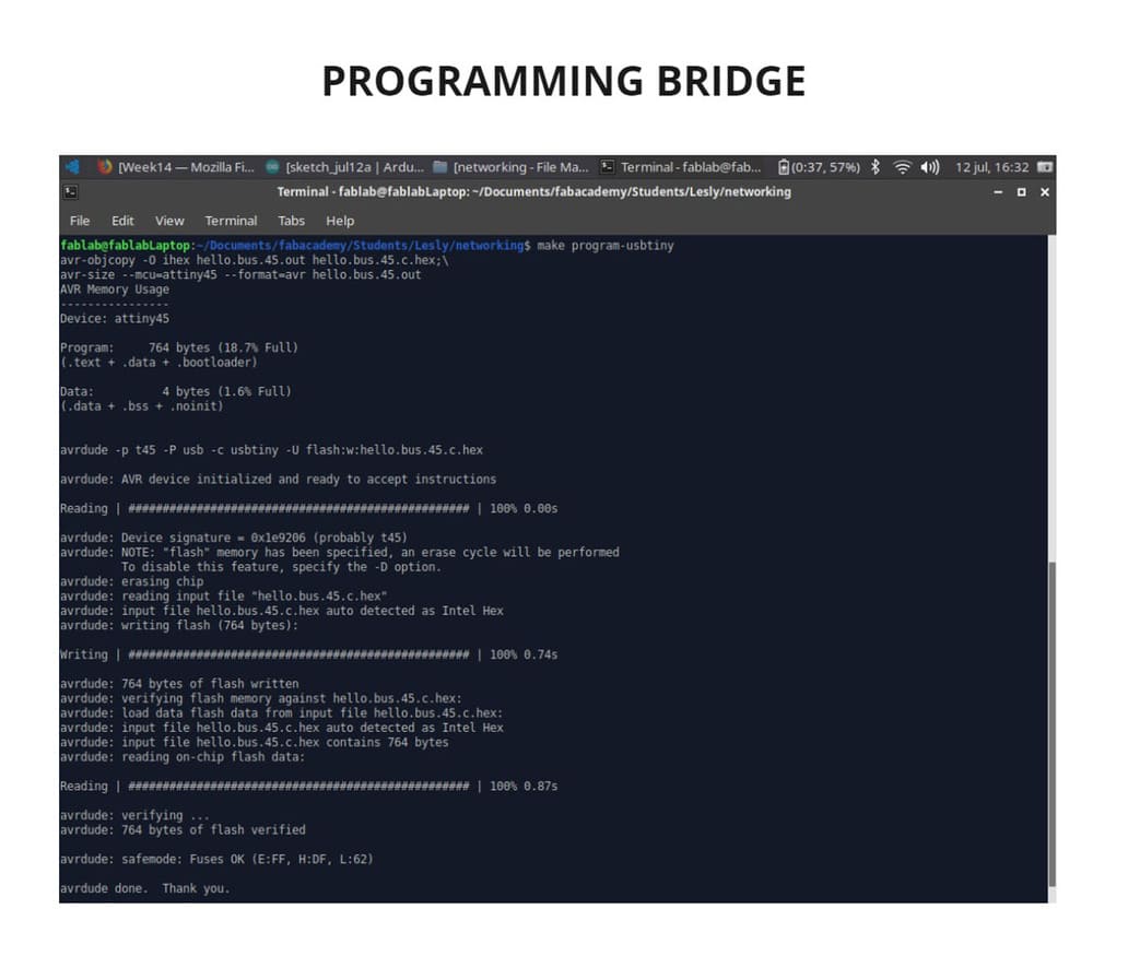
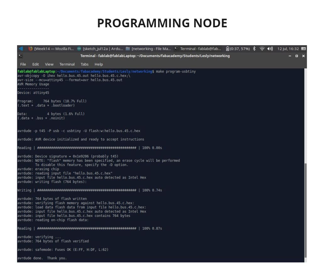
I entered the folder where the file was located using the
LINUX TERMINALand finally wrote themake program-usbtinycode. -
The message
FUSES OKappeared, so the programming was correct.
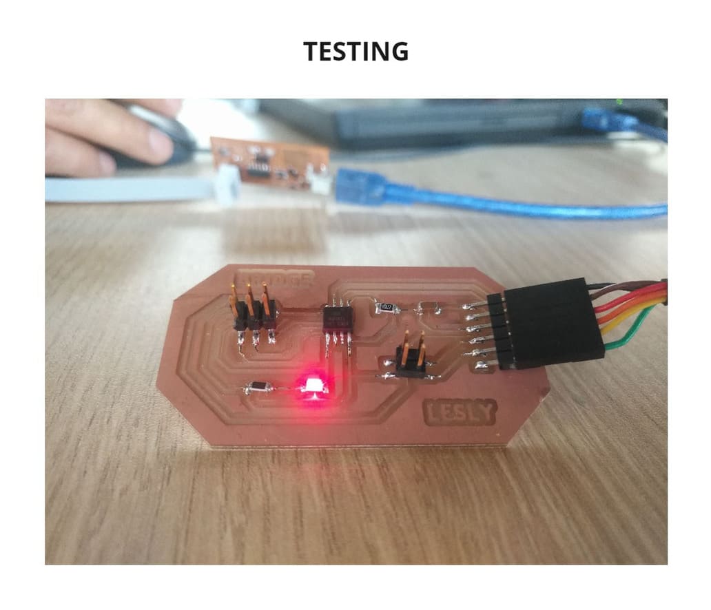
NOW IT’S TIME TO TEST IT!
-
I disconnected the ISP cable and only the FTDI stayed connected.
-
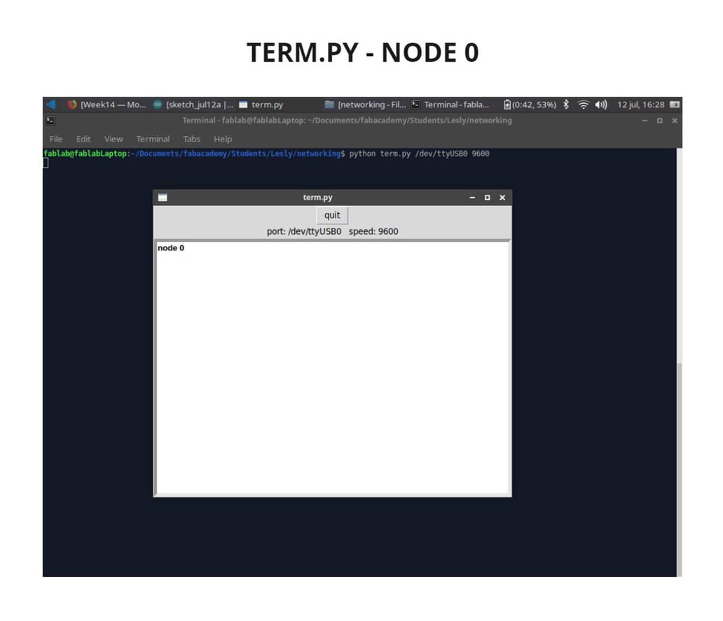
To test it, I used TERM.PY, download it from the following link: TERMY.PY , this will help us to monitor serial data.
-
Following the tutorial by Babken Chugaszyan, I went to the folder where the file was located and through the LINUX TERMINAL, I typed the command
sudo python term.py /dev/ttyUSB0 9600, because I am using a FTDI cable. -
A new window appeared in which every time I pressed
0on my computer keyboard,NODE 0appeared on the screen and the BRIDGE led lit up.
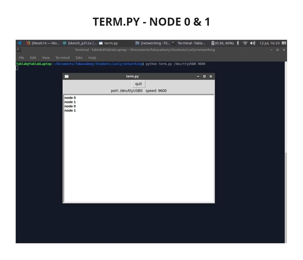
I followed the same steps to program the NODE, but this time instead of node_id '0', I changed it to node_id '1', as I wanted it to respond to a different value than the BRIDGE. I usedLINUX TERMINAL and wrote the make program-usbtiny code and and the message FUSES OK appeared, all programming was ok.
I finally tested both in TERM.PY and it recognized them:
-
Each time I typed
0, the messageNODE 0appeared on the screen and the BRIDGE led lit up. -
Each time I typed
1, the messageNODE 1appeared on the screen and the NODE led lit up.
You can see it in the video below:
VIDEO

I also tried to make an additional node to place it value 2, I programmed it and it worked individually, but when I connected them to the rest of the boards, it did not work, I still do not understand what happened but at least I was able to communicate a NODE and a BRIDGE in this assignment, I feel satisfied for having achieved it.
2. GROUP ASSIGNMENT
WHAT IS THE PURPOSE OF THIS ASSIGNMENT?
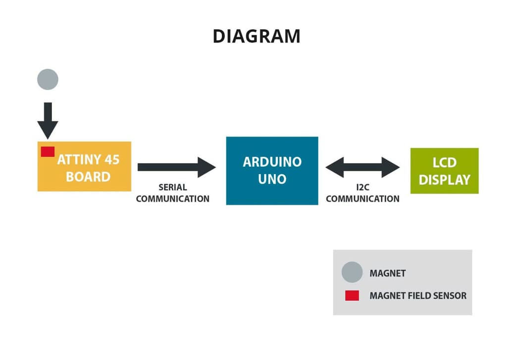
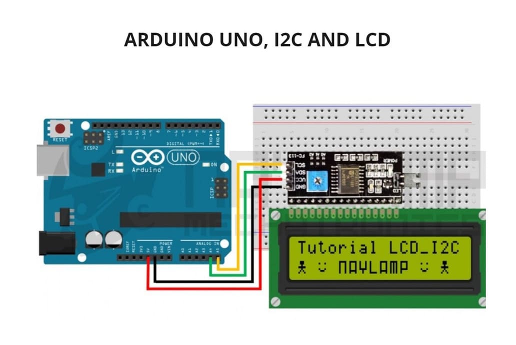
To get two projects to communicate, I will use my Input board and the Arduino Uno board through serial communication.
HOW IS IT ACHIEVED? WHAT KIND OF DATA WILL BE SENT?
My Input board has a magnetic field sensor, as long as it is close to a magnet it will send analog data to it and this will be reflected on an LCD display.
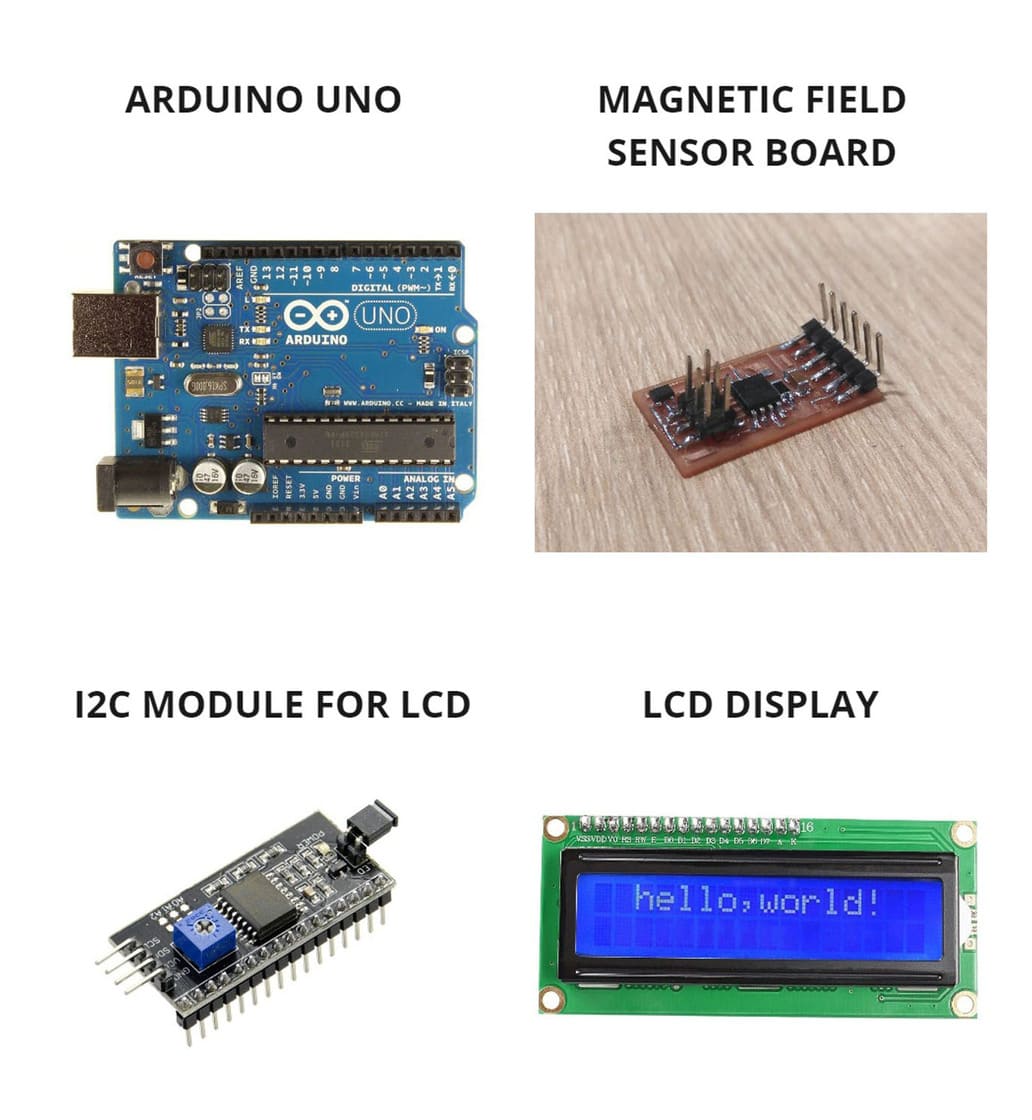
WILL YOU USE ANY ADDITIONAL ELEMENTS?
Yes, an I2C adapter module to communicate the LCD and ARDUINO UNO, also a Protoboard for GND and VCC signals, finally a battery as a power supply.
WHAT TYPE OF INPUT DEVICE ARE YOU GOING TO USE?
I decided to made the hello.mag.45 board which has a magnetic field sensor that I saw in Input Devices week, following the same guidelines as in my other boards.
This is Neil’s example that I used as a guide:MAGNETIC FIELD SENSOR - ATTINY45
This is the datasheet for each element to be used:
You can see the photo of each one and a diagram of how they work together:
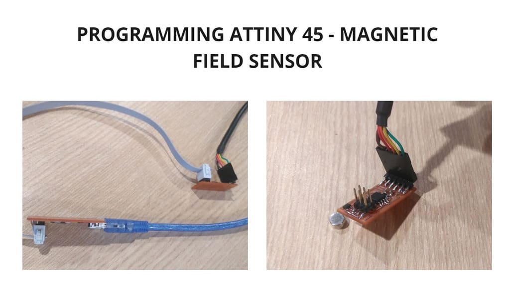
PROGRAMMING ATTINY 45
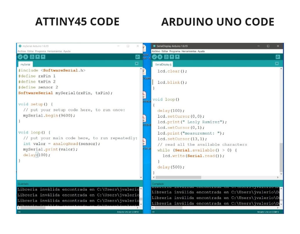
This is the code I used to program the board with the magnetic field sensor and Attiny 45:
#include <SoftwareSerial.h>
#define rxPin 1
#define txPin 2
#define sensor 2
SoftwareSerial mySerial(rxPin, txPin);

void setup() {
  // put your setup code here, to run once:
  mySerial.begin(9600);
}

void loop() {
  // put your main code here, to run repeatedly:
  int valor = analogRead(sensor);
  mySerial.print(valor);
  delay(100);
}
-
The Rx and Tx pins are reversed, it was unexpected but could be programmed by changing the value of each in the code.
-
You can view information about the pins and their functions here: ATTINY 45 DATASHEET.
-
I used
PIN 2to transmit information from the sensor to the serial port that is connected to the computer. -
The code indicates
mySerial.begin(9600);, but when tested with the SERIAL MONITOR, it recognized the values at1200 BAUD. So for communication with other boards, I should use the value of1200.
The analog signals that you will see on MONITOR SERIAL from Arduino IDE, ranging from 0 to 1023. You can see the details in the following link: ANALOG READ.
The programming was successful because the analog signals could be read and values were displayed that varied according to the proximity or remoteness of the sensor to the magnet.
PROGRAMMING ARDUINO UNO
Remember that you must make the connections of the LCD DISPLAY, ARDUINO UNO and the I2C ADAPTER MODULE, I used this example as a guide to identify the connections:
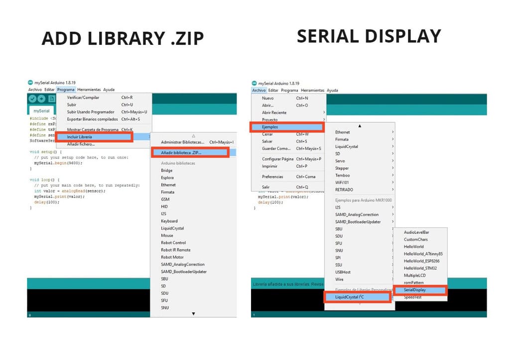
To start programming, first I had to install a library called LIQUID CRYSTAL I2C to be able to use the LCD display with the I2C APADTER MODULE.
Download the library at the following link:
Then I had to follow these steps to install it:
-
Go to
PROGRAM > INCLUDE LIBRARY > ADD LIBRARY.ZIP, find the ZIP file called:LiquidCrystal_I2C-master, click and install it. -
Then go to:
FILES > EXAMPLES > LiquidCrystal I2C > SerialDisplay.
This is a tutorial to learn more about how it works:
Finally I will place the code, I used the SerialDisplay example, but I modified it and this is the result:
#include <Wire.h> //for ESP8266 use bug free i2c driver https://github.com/enjoyneering/ESP8266-I2C-Driver
#include <LiquidCrystal_I2C.h>

#define COLUMS 16
#define ROWS   2

#define PAGE   ((COLUMS) * (ROWS))

uint8_t char_counter = 0;

LiquidCrystal_I2C lcd(PCF8574_ADDR_A21_A11_A01, 4, 5, 6, 16, 11, 12, 13, 14, POSITIVE);

void setup()
{
  Serial.begin(1200);

  while (lcd.begin(COLUMS, ROWS) != 1) //colums - 20, rows - 4
  {
    Serial.println(F("PCF8574 is not connected or lcd pins declaration is wrong. Only pins numbers: 4,5,6,16,11,12,13,14 are legal."));
    delay(5000);
  }

  lcd.print(F("FAB ACADEMY 2022"));    //(F()) saves string to flash & keeps dynamic memory free
  delay(2000);

  lcd.clear();

  lcd.blink();
}

void loop()
{
  delay(100);
  lcd.setCursor(0,0);
  lcd.print(" Lesly Ramirez");
  lcd.setCursor(0,1);
  lcd.print("measurement: ");
  lcd.setCursor(13,1);
  // read all the available characters
  while (Serial.available() > 0) {
    // display each character to the LCD
    lcd.write(Serial.read());
  }
  delay(500);
}
I made these changes because:
- My LCD display has 16 COLUMNS and 2 ROWS, so I indicated:
#define COLUMS 16
#define ROWS 2
- The value that the MONITOR SERIAL from Arduino IDE was
1200, so I wrote:
Serial.begin(1200)
- The screen message I wanted to display was
FAB ACADEMY 2022, so I specified
lcd.print(F("FAB ACADEMY 2022"));
- The last change in
Void loopmeans that every time it starts, the screen will take 100ms to turn on or restart, the messages :Lesly Ramirez,measurement:and the analog value that the sensor emits will be seen on the screen.
Here you can see the difference in the codes:
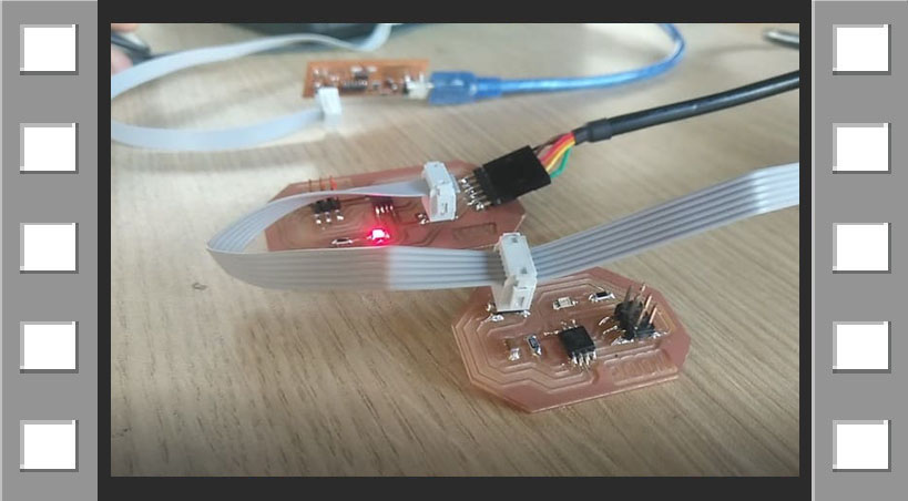
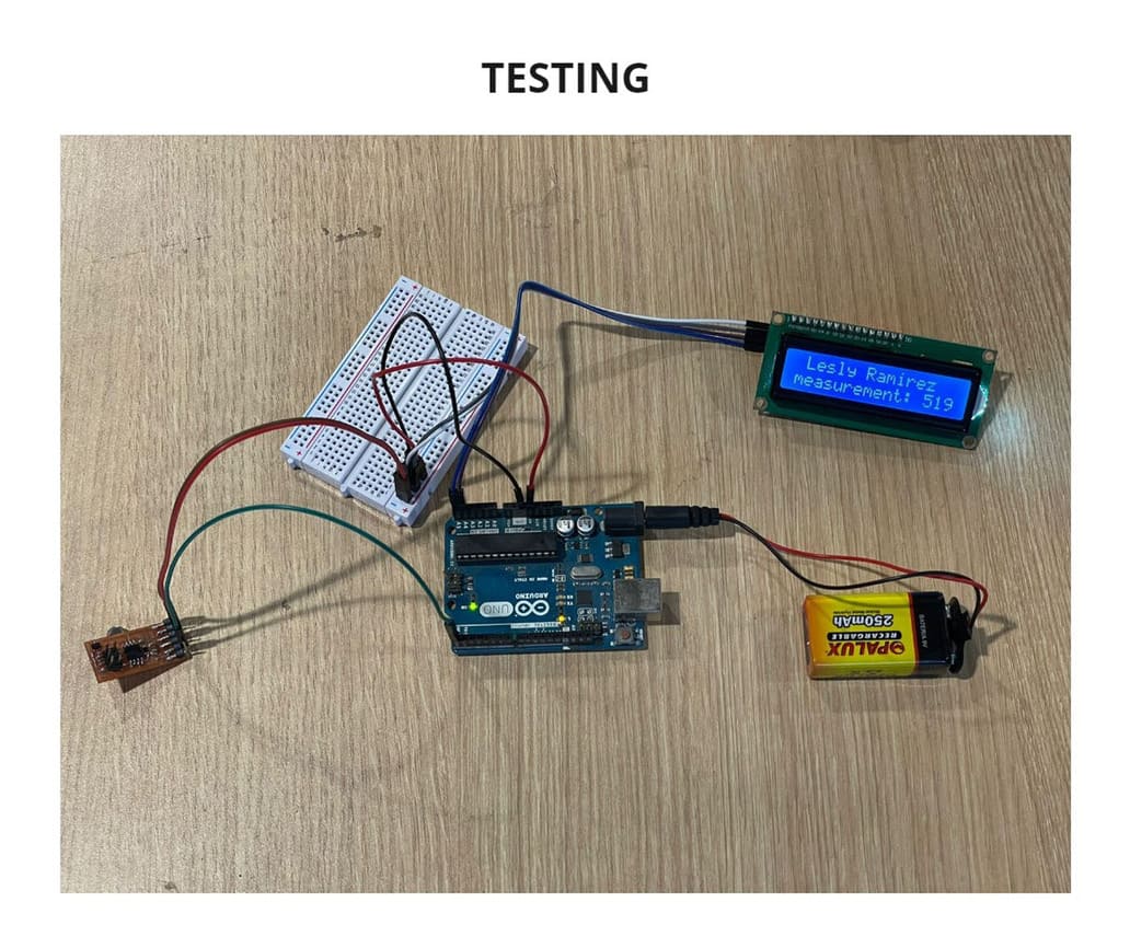
TESTING
-
I used a battery as a power supply so you can see that it does work without being connected to the computer.
-
I connected the I2C adapter module to the LCD display.
-
I connected the Arduino UNO via USB port to the computer, I also connect the I2C to the Arduino via jumpers and to the Protoboard.
-
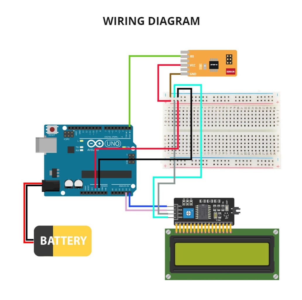
Finally , I connected my Input board to the Arduino UNO and the Protoboard.
Finally you can see the analog values that are perceived by the magnetic field sensor on the LCD display, these values vary from 0 to 1023 according to the positive or negative polarity of the magnet.
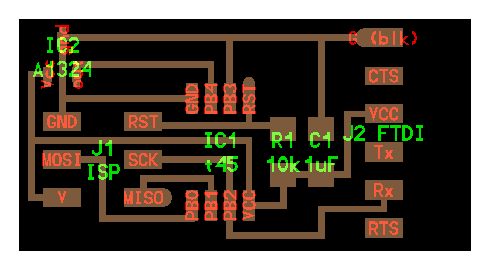
I made a diagram about the wiring connections, I also attach the actual photo of the result and the video:
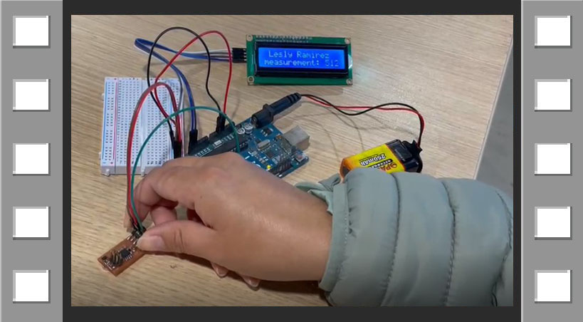
VIDEO

3. CONCLUSIONS
-
If something does not work, check the documentation of someone who has done a project similar to yours, this will help you learn and solve doubts. That’s why it’s important to document details such as errors and how they were solved, because it helps others to learn.
-
To visualize the serial port data we have not only the Arduino IDE, but also TERM.PY and these will be of great help to us. I have been able to show the response of the NODE and BRIDGE according to the value given to each.
-
If you do not know how to connect the devices you are going to use, you should look for their data sheet, check the functions of their pins and look for examples where others have already done it, otherwise you will waste a lot of time trying to understand how it works or you will make the wrong connections.
-
The use of the LCD DISPLAY can be applied to multiple projects, beyond using a magnetic sensor (like the one I used), I found it very interesting and learned more about how to work together with different types of boards.