15. Interface and application programming
Group assignment:
- Compare as many tool options as possible.
Individual assignment:
- Write an application that interfaces a user with an input and/or output device that you made
1. GROUP ASSIGNMENT
I decided to use two types of software to experiment with the interfaces, Processing and MIT App Inventor.
PROCESSING
I decided to try this software PROCESSING IDE, reminds me a lot of the ARDUINO IDE, but with the difference that I can see a graphical interface that a user can interact with. You can download here:
My point of departure was the example of RECURSIVE TREE, in which I started to read and analyze the code because I found it very interesting to use fractals and generate that change.
I started to change values in the codes and got different results such as:
-
Increasing or decreasing the number of branches.
-
Change the size of the display window.
-
Change the background or object color.
-
Change the rotation angle.
And there are many more parameters that can be modified but they are for a reason and have a limit for certain values, because if you exceed that limit, the program will automatically show you that the code is wrong and is impossible to read.
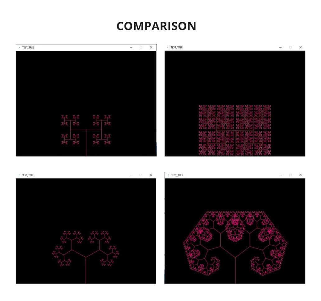
These are the changes I made and their results:
- Here is displayed the size of the window in which you will visualize the graph:
size(640,480)
- This is the background color, you can choose the one you want, you only have to place its RGB code:
background(255,153,255)
- This is the color of the object you are coding, enter the RGB code of your choice:
stroke(255,0,127)
- This is the angle of rotation that your object will travel and according to that will be the limits of the movement:
float a = (mouseX / (float) width) * 180f;
- This is the number of branches the design will have:
h *= 0.7;
I tried to override the limits and tried to use the value 1 or 0.9, but I got the message: pushMatrix() cannot use push more than 32 itemsand the graphical interface window was not responding.
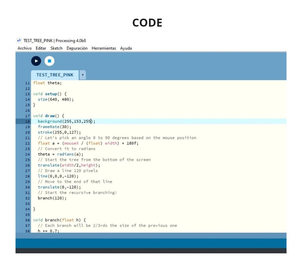
This is the complete code and you will see the results in the photo below, as well as the video of the process and result:
float theta;

void setup() {
  size(640, 480);
}

void draw() {
  background(255,153,255);
  frameRate(30);
  stroke(255,0,127);
  // Let's pick an angle 0 to 90 degrees based on the mouse position
  float a = (mouseX / (float) width) * 180f;
  // Convert it to radians
  theta = radians(a);
  // Start the tree from the bottom of the screen
  translate(width/2,height);
  // Draw a line 120 pixels
  line(0,0,0,-120);
  // Move to the end of that line
  translate(0,-120);
  // Start the recursive branching!
  branch(120);

}

void branch(float h) {
  // Each branch will be 2/3rds the size of the previous one
  h *= 0.7;

  // All recursive functions must have an exit condition!!!!
  // Here, ours is when the length of the branch is 2 pixels or less
  if (h > 2) {
    pushMatrix();    // Save the current state of transformation (i.e. where are we now)
    rotate(theta);   // Rotate by theta
    line(0, 0, 0, -h);  // Draw the branch
    translate(0, -h); // Move to the end of the branch
    branch(h);       // Ok, now call myself to draw two new branches!!
    popMatrix();     // Whenever we get back here, we "pop" in order to restore the previous matrix state

    // Repeat the same thing, only branch off to the "left" this time!
    pushMatrix();
    rotate(-theta);
    line(0, 0, 0, -h);
    translate(0, -h);
    branch(h);
    popMatrix();
  }
}
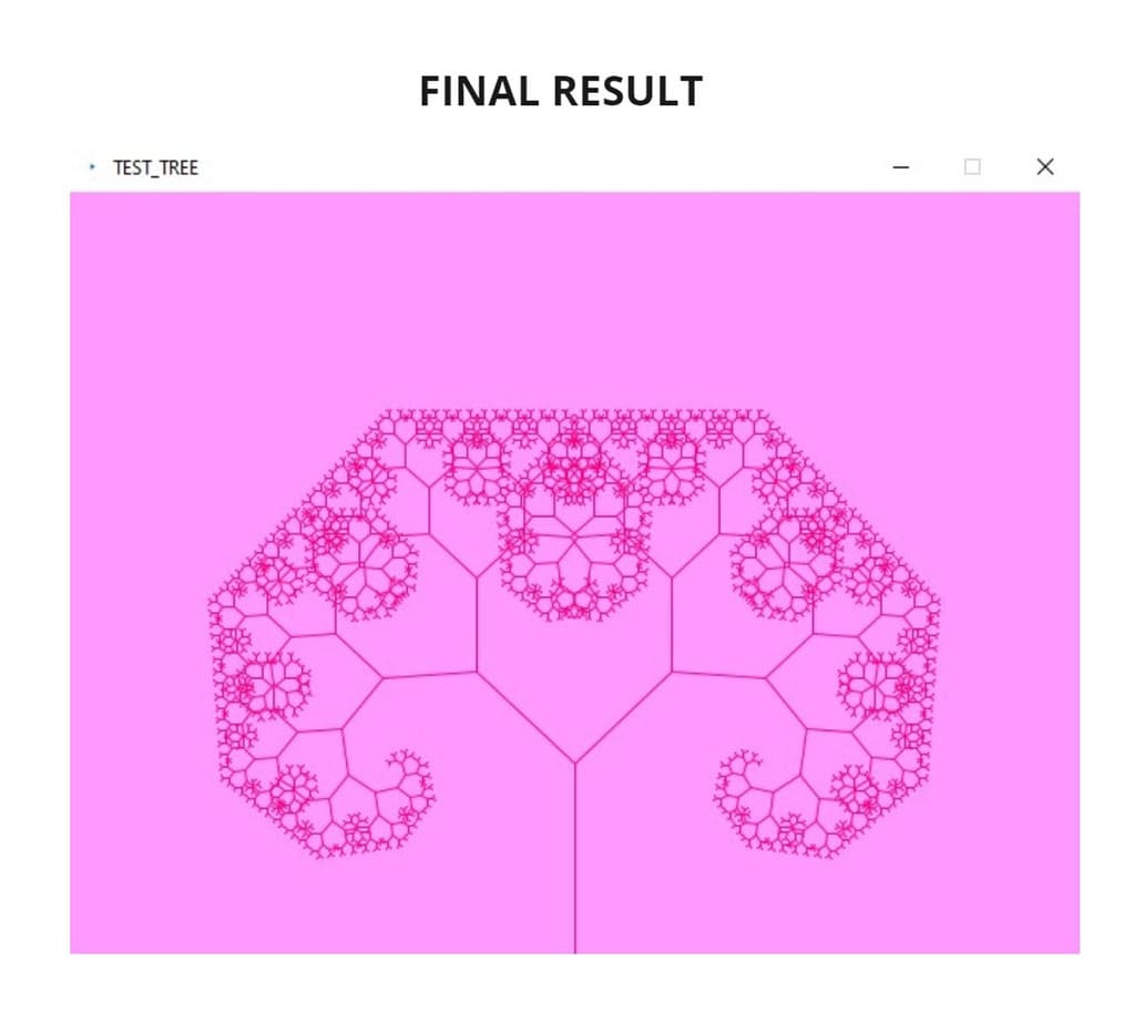
The image does not change by itself, but follows the mouse cursor, as it moves to the left and right the shape opens and closes, changing the position and showing the fractal tree.
I did a little more research and found out that you can even use Processing from your cell phone and make your own applications there. You can also connect to input or output boards (as I did in the individual assignment).
It seems to me a very interesting software where you can do great things but you have to know which commands to use and their limits, because otherwise it can become unreadable for the program and you will see the message: ERROR.
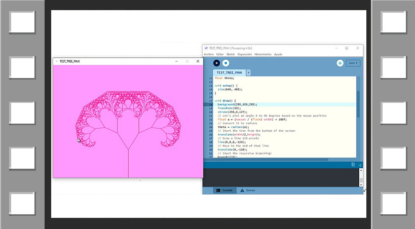
As I made changes to the commands, the results changed, from the angle at which it rotated, to the amount of branching, color and more, you can see the details in the video below:
VIDEO

MIT APP INVENTOR
I decided to use App Inventor and create a basic mp3 player with PLAY, PAUSE and STOP buttons. Here is the official website:
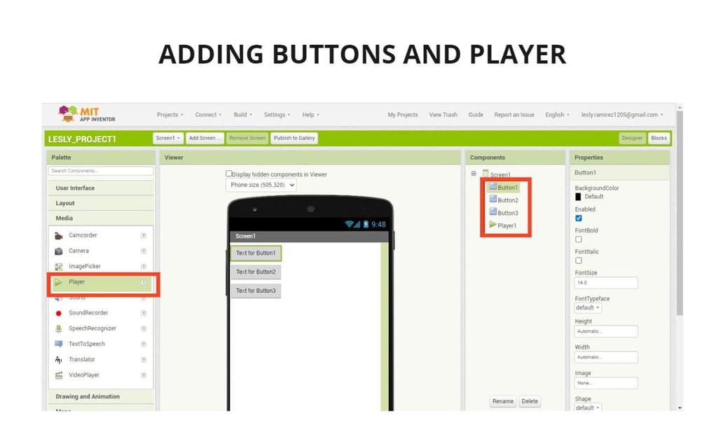
First, go to CREAT APPS button, then create an account or log in if you already have one. Click onSTART NEW PROJECT, name your project and you will get a window with 4 principal sections :
-
PALETTE: Add buttons, images, player, etc. to your app
-
VIEWER: Here you can see how your application will look like in real time.
-
COMPONENTS: Here you can see the components you have already added.
-
PROPERTIES: Here you can modify the characteristics of the components.
I added buttons to which I assigned names such as PLAY, PAUSE and STOP. I also added a song in .mp3 format.
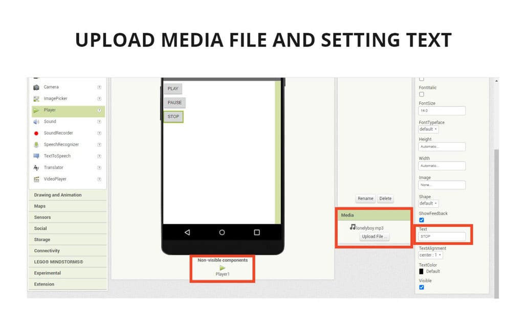
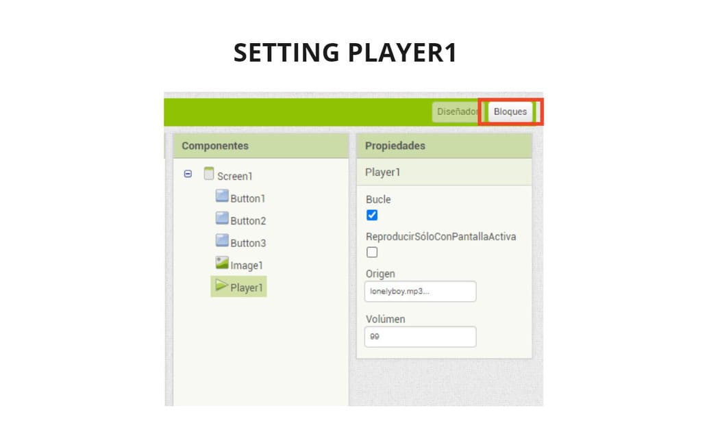
The song is Looped so that it stops only when the PAUSE or STOP buttons are pressed. I set the volume to 99 because I want it to sound good.
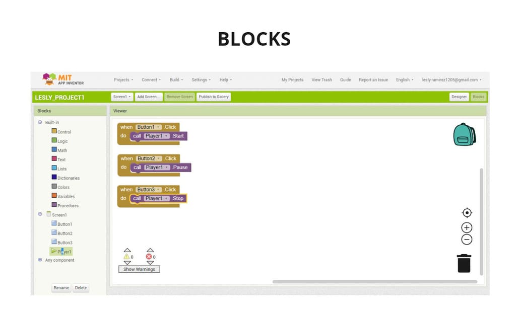
Then I went to the BLOCKS section, gave each button an action, each one was going to perform an action. Each one was going to be calling the player but for different functions: START, PAUSE and STOP.
It was like putting together a puzzle, it’s a very fun and easy way to learn to program.
You can also add an image so that it can be seen on the screen, I added one and adjusted it to the size of the screen space.
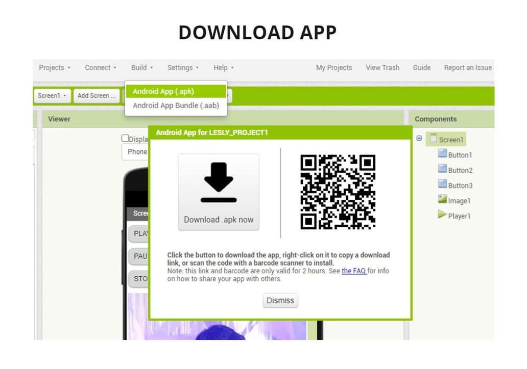
Finally I download the application, there are two formats available .apk and .abb. I chose .apk because I could download the application using a QR SCANNER and it saves a lot of time and steps to install it.
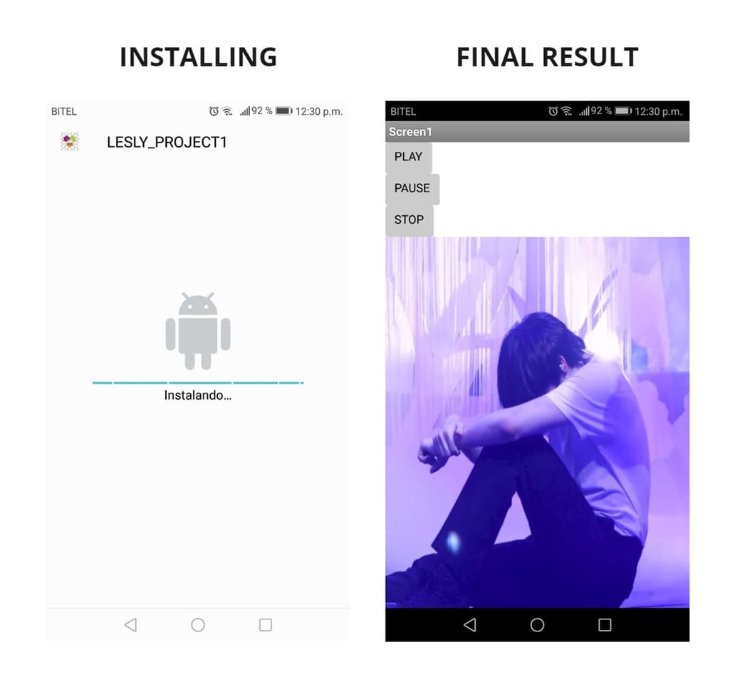
When I finished installing it, I realized that the image I added had been elongated, it turns out that when configured to the size of the screen space, it will lengthen or shrink according to the cell phone in which it is downloaded, it does not look so bad but it is something that can be improved.
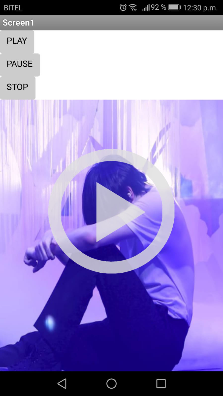
And my application works! These are the results, look at the pictures and video:
I recorded this video from my own cell phone and each button turns light gray each time it is pressed, so the music starts or stops.
VIDEO

Having experimented with Processing and MIT App Inventor, I would like to be able to combine these two applications in some way. I know that there are already applications that show the spectrum of the songs while they play but it is not the same that the interface moves one or more images according to the music, that is to say one is linked to the other and scenes of animated objects can be developed, without having to use several programs, but only one.
I have become more curious to be able to make ideas come true and I know that knowing about programming is very necessary to develop projects of all kinds.
2. INDIVIDUAL ASSIGNMENT
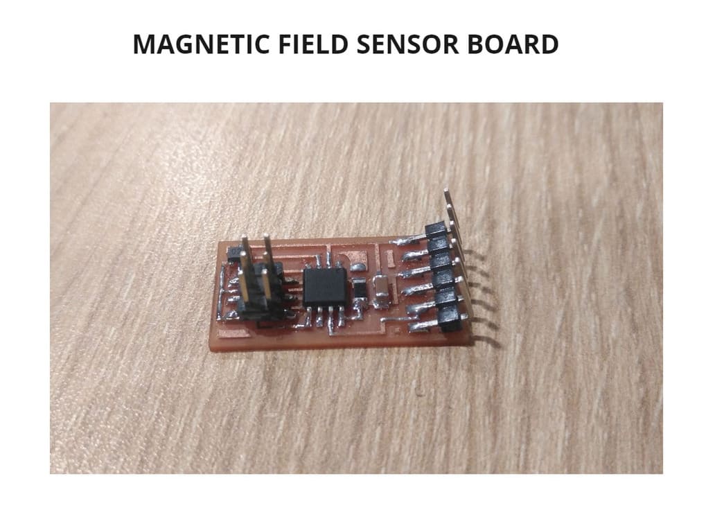
For this assignment I decided to develop a magnetic field sensor board:
BOARD
I followed the same steps that I did in the ELECTRONICS DESIGN and ELECTRONICS PRODUCTION, the tips and recommendations and this is the result:
PROGRAMMING
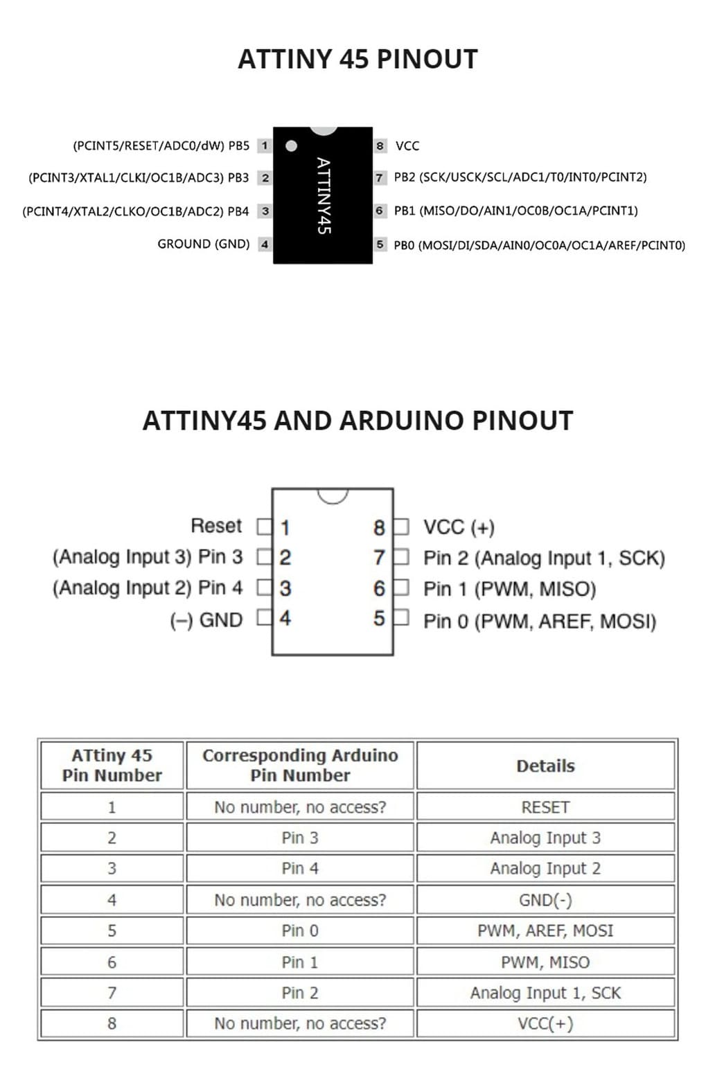
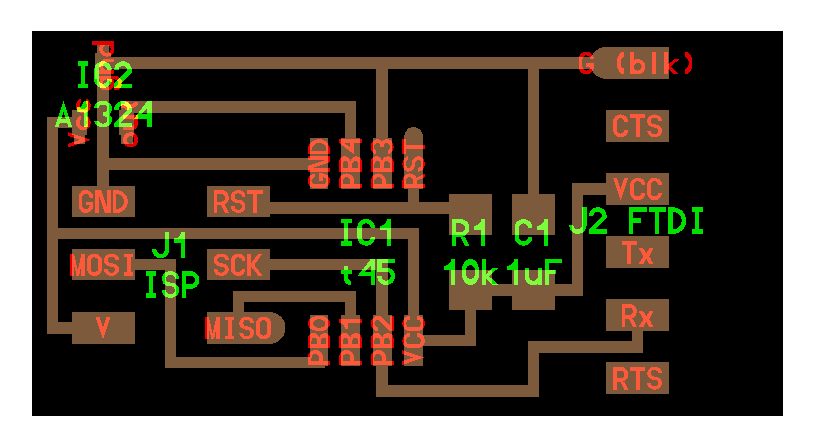
To program I had to take into account the pins and their functions. Because I used ARDUINO IDE, knowing the equivalent and reviewing the datasheet is important:
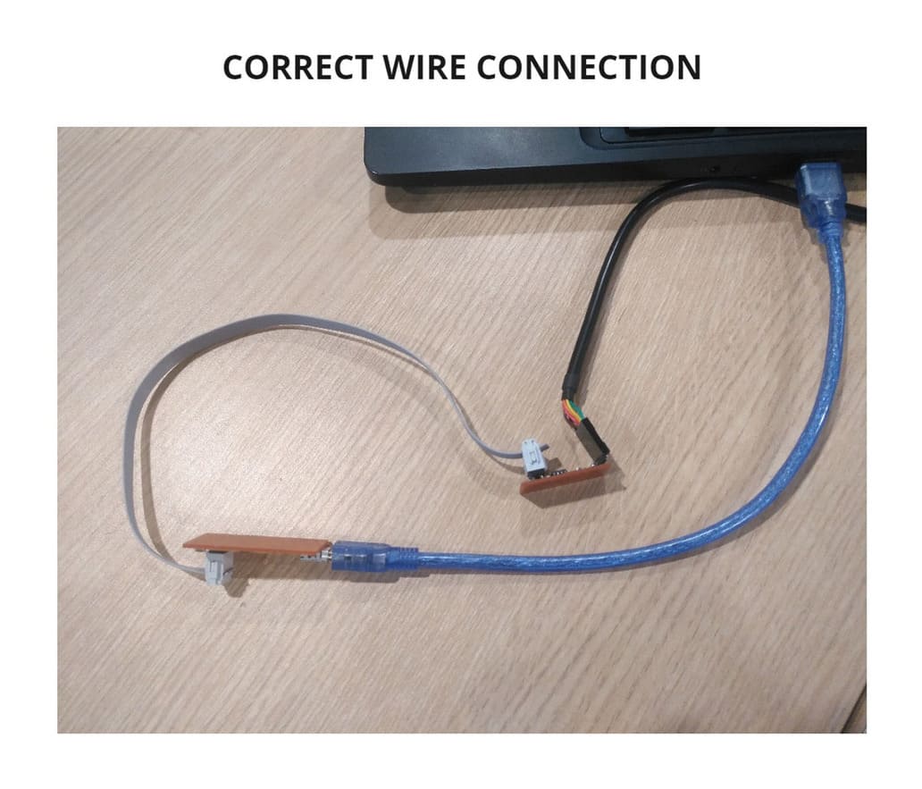
Remember to correctly connect your board with the programmer to the pc, you have to configure the type of board, processor, port, clock and programmer to be able to program the ATTINY45. I followed the same steps that I did in the EMBEDDED PROGRAMMING WEEK but with this type of microcontroller.
You can see the detail in the images below:
Then I indicated the code, there were problems in the pin recognition and I will explain how I solved it:
- To program in ARDUINO IDE, I had to check the pins and place the correct values. For communication, the
PB2 (PIN 7 ATtiny45) ≅ PIN 2 (Arduino)was being used because it is connected to theRXof the FTDI, so it was assigned the value2. The sensor should also be connected to this pin, it is the only one that serves to communicate by the design of this board and therefore it was assigned the value2and finally also had to assign the value toTXalthough there was nothing connected to it, so I put the value1, since it would not interfere to have no connection to this pin.
This is what the initial part of the programming should look like:
#define txPin 1
#define rxPin 2
#define sensor 2
I did put the rest of the code, but for some reason it didn’t work, so I made a change in the initial part:
#define rxPin 1
#define txPin 2
#define sensor 2
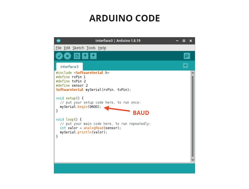
I swapped places, the RX instead of TX and it worked, although this left me very confused, apparently they were reversed. This is the complete code I used:
#include <SoftwareSerial.h>
#define rxPin 1
#define txPin 2
#define sensor 2
SoftwareSerial mySerial(rxPin, txPin);

void setup() {
  // put your setup code here, to run once:
  mySerial.begin(9600);
}

void loop() {
  // put your main code here, to run repeatedly:
  int valor = analogRead(sensor);
  mySerial.println(valor);
}
-
In the code you can see that the serial should respond to 9600:
mySerial.begin(9600); read the analog value of the sensor :int value = analogRead(sensor); finally print that value :mySerial.println(value). -
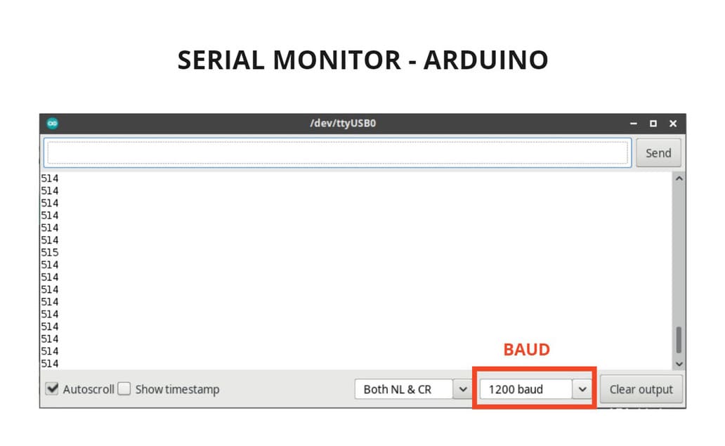
When I tested it with the SERIAL MONITOR, it did not read with 9600 BAUD, this was strange, so I started to test with other values and it started to read with 1200 BAUD, this means that the eighth part was used. WHY? I am not sure but it is possibly a problem of the internal clock of the microcontroller.
-
It worked, the analog signals, ranging from 0 to 1023, could be displayed. You can see the details in the following link: ANALOG READ. This means that when the MAGNETIC FIELD SENSOR is close to an object with polarity like a magnet, its value will change according to the pole in which it is, it will go up or down depending on the Negative or Positive Polarity. If it does not perceive objects with polarity nearby, the value it will show will be intermediate, on average it will be 514 approx.
You can see the details in the following pictures:
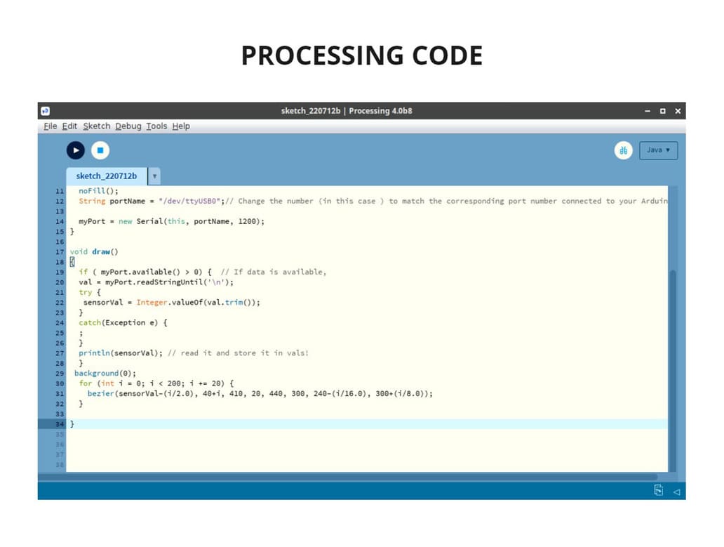
In order to create an application that interacts with my sensor, I used the PROCESSING program, you can download it here:
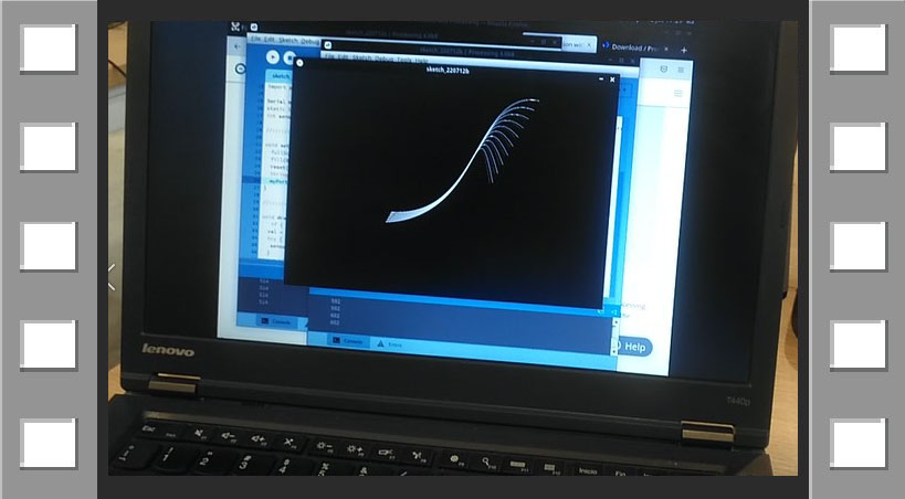
I used a basic example of PROCESSING, called BEZIER, you can see more details here: BEZIER EXAMPLE.
First the serial port is defined, I used the Usbtiny, that’s why my port name is represented as "/dev/ttyUSB0". I placed the value 1200 in the myPort section, because even though it was programmed with 9600, only the signal at 1200 BAUD was detected with the Arduino’s SERIAL MONITOR.
The original code showed this part:
size(640, 360);
 stroke(255);
I changed to :
 size(720, 480);
 stroke(255);
This way I could see the differences that were slight in the size of the curves.
The numbers you can see at the bottom of the code are the part that originates the shape of each bezier, the formula and conditions that must be met.
This is the complete code:
import processing.serial.*;

Serial myPort;  // Create object from Serial class
static String val;    // Data received from the serial port
int sensorVal = 0;

void setup()
{
  size(720, 480);
  stroke(255);
  noFill();
  String portName = "/dev/ttyUSB0";// Change the number (in this case ) to match the corresponding port number connected to your Arduino.

  myPort = new Serial(this, portName, 1200);
}

void draw()
{
  if ( myPort.available() > 0) {  // If data is available,
  val = myPort.readStringUntil('\n');
  try {
   sensorVal = Integer.valueOf(val.trim());
  }
  catch(Exception e) {
  ;
  }
  println(sensorVal); // read it and store it in vals!
  }
 background(0);
  for (int i = 0; i < 200; i += 20) {
    bezier(sensorVal-(i/2.0), 40+i, 410, 20, 440, 300, 240-(i/16.0), 300+(i/8.0));
  }

}
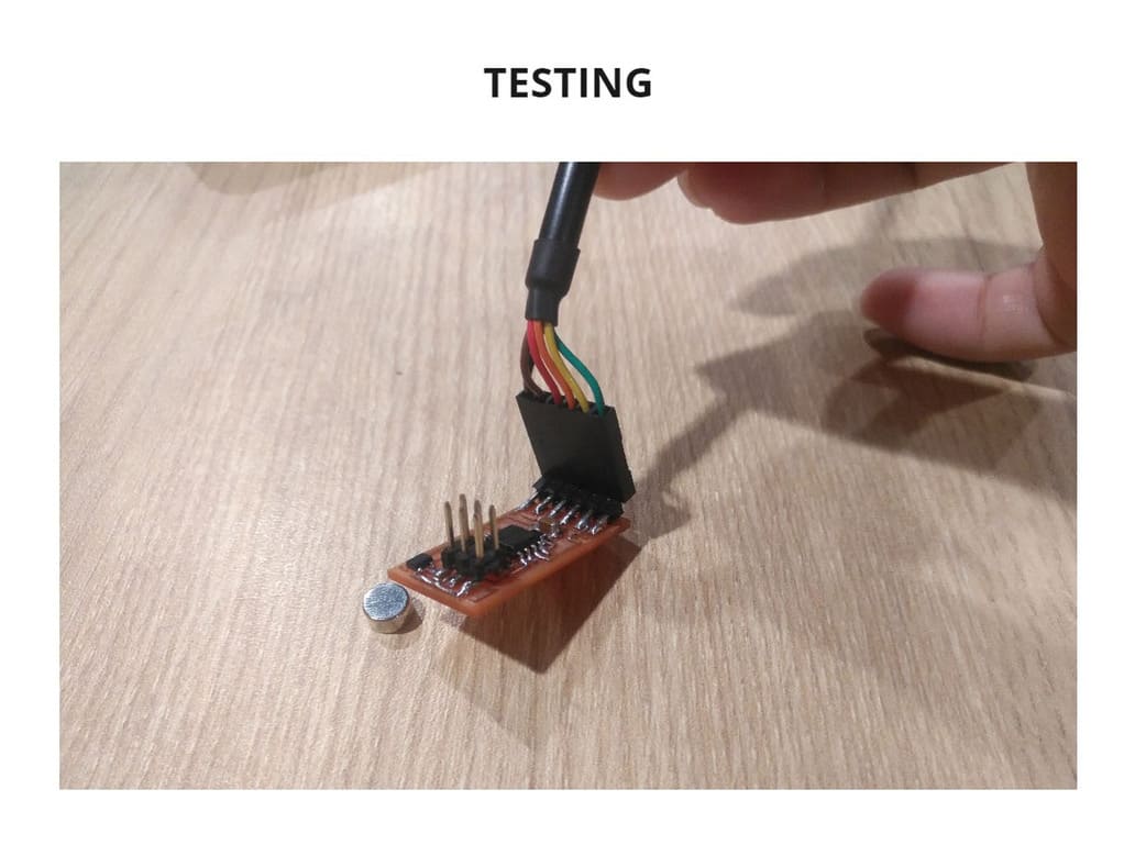
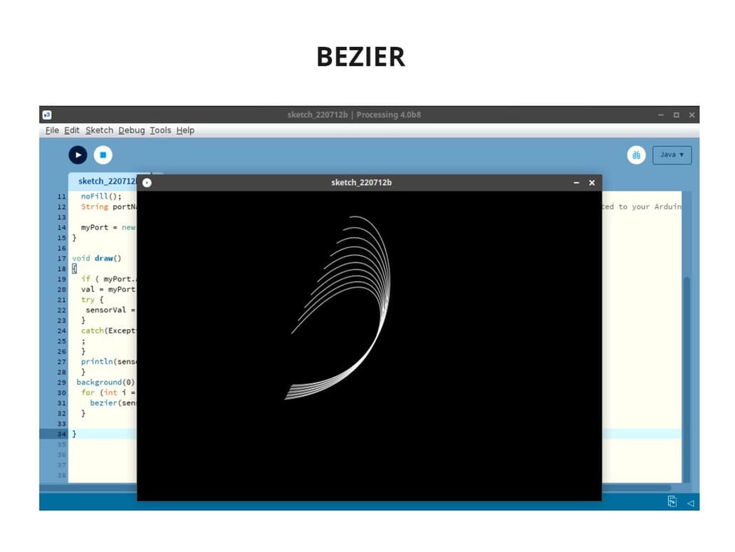
TESTING
As I moved the sensor closer to the magnet, the bezier elongated to the left or right, depending on the polarity of the magnet, as it has 2 sides (positive polarity and negative polarity).
It worked! It is amazing how the responses of a sensor can be represented, not only transformed into numbers or signals, but also into graphs.
Here are the photos and video:
VIDEO

3. CONCLUSIONS
-
Processing is an application in which you can configure from the most basic to more complex things, observe them graphically and interact with it. You can even create applications from your cell phone, which makes it more accessible for those who don’t have a computer.
-
The Arduino IDE’s serial monitor will be very useful to confirm if you are getting a response according to the indicated speed or if there is a variation or anomaly. If something is wrong, the serial monitor will indicate strange symbols that cannot be read as a whole and do not make any sense.
-
It can take hours to find the error in a programming, but inverting certain values can be the answer, it has happened to me on previous boards where the values were inverted and now the RX and TX were inverted.
-
Be careful in the changes you make in the code, always have a backup copy or you will end up losing everything you have done.
-
MIT APP Inventor is very intuitive and easy to handle, it reminds me of Scratch, putting everything together like a puzzle. These are programs that push you to learn more about programming, especially if you are just starting in this subject.