3. Computer Aided design
Assignment
- Model (raster, vector, 2D, 3D, render, animate, simulate, …) a possible final project, compress your images and videos, and post it on your class page
We come to the second week, we have to make designs using 2d and 3d programs. To be honest, I have experimented with 2d and 3d programs before, like Photoshop, Autocad and Revit, which I learned to apply to the architecture branch. Below, you will see that I am applying it to other types of designs and there are also peculiar ways to use certain programs.
Join me to see what I’ve experienced!
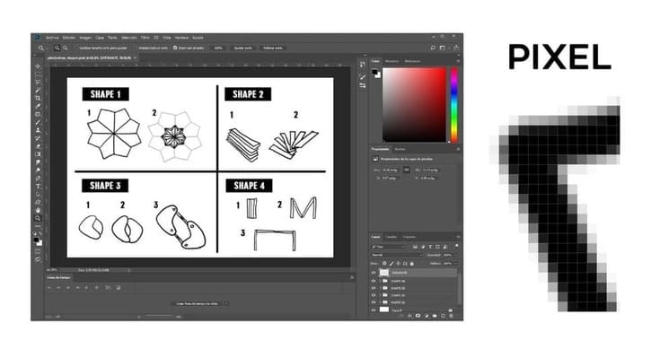
1. PHOTOSHOP
DRAWING
First of all, you have to understand that this is a rasterization program, that means that if you work on a design and you use ZOOM, you will be able to see some squares also called pixels, which is the minimum unit of a digital image.
-
I opened a new file, setting it in RGB, because it will be published on this website (RBG is for digital formats and CMYK for print formats such as cards, posters, invitations, etc).
-
I made drawings with the tools
BRUSH,TEXTandRECTANGULAR FRAME, I worked using layers to keep order and not affect the final design. -
When you use
ZOOM, you can verify that it is formed by the pixels.
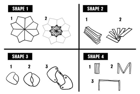
Things on which I based to propose my modular folding project, is the engineering of paper as found in pop up books, created with origami and kirigami, as well as the dilation of the diaphragm of the cameras, movement of umbrellas and folding furniture.
You can use Photoshop to draw your ideas. You can use your computer mouse or a graphic tablet to draw.
I learned a little bit of Photoshop, to be able to improve the presentation panel of my architectural projects. But I felt that I was falling short by just making edits, so I started experimenting by watching youtube tutorials so I tried to make a video with photoshop:
STOP MOTION IN PHOTOSHOP
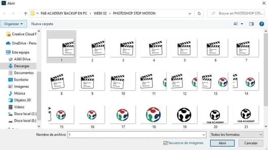
Yes, you can make a stop motion video with Photoshop, it is much easier than it seems. You must have your images ordered and numbered in your gallery.
To be honest, I also used Illustrator, because it was easier to work with multiple work tables.
-
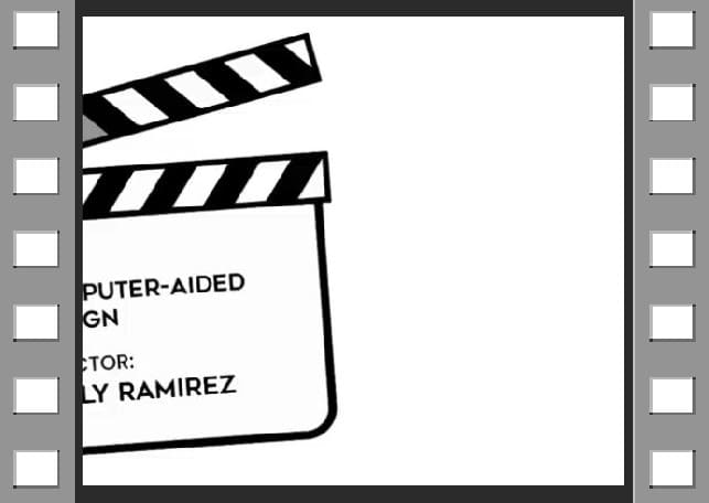
First I added the image of a clapperboard, vectorized it with
IMAGE TRACE, repeated the same step with the Fab academy logo (You can see more details in the Illustrator tutorial below). -
I added a text with the
TEXTtool, I also made a black and white version of the Fab Academy logo, changing the color with anALT + BACKSPACE(It depends on the order it is in the palette). -
I copied work table multiple times and each time the images were tilted a little, giving a sense of movement, so I generated 21 images in total.
-
With the tool
EXPORT>EXPORT AS, choosingTYPE: .JPGand enablingUSE WORK TABLES. Each image was exported individually and I did not need to edit any more. -
Do not forget to put in a folder all the images together, number them in order, it is very important.
Once you have all your images sorted, open Photoshop and follow the steps:
-
Click on
ARCHIVE>OPEN, then go to the folder where you saved the pictures, click on the first image and activate theIMAGE SEQUENCEoption. -
You will see a
TIMELINEas if you were in a video editor. If you can’t see it, go to theWINDOWin the Menu Bar and chooseTimeline. -
You can save it by clicking
File>Export>Render video.
VIDEO

CONCLUSIONS:
-
If you want to make stop motion from 2d images as vectors, I recommend After effects as it gives you more control over the vector. In photoshop, you can only modify frame by frame for each image, which is very tedious.
-
For stop motion videos with photos is very useful.
-
Photoshop is better for image editings such as retouching, sketch drawings, character design, or scenarios, but a 2d software for parametric design I recommend programs like Illustrator, Inkscape, among others.
2. ILLUSTRATOR
It is a vectorization program. If you make zoom in, you will not see pixels. It is much more accurate if you want to work with measurements and this is one of the favorite programs of designers. Discover with me what this program can do!
FROM RASTER TO VECTOR
Can I convert an image from raster to vector?
The answer is YES, just open the image in the program and follow the steps below:
-
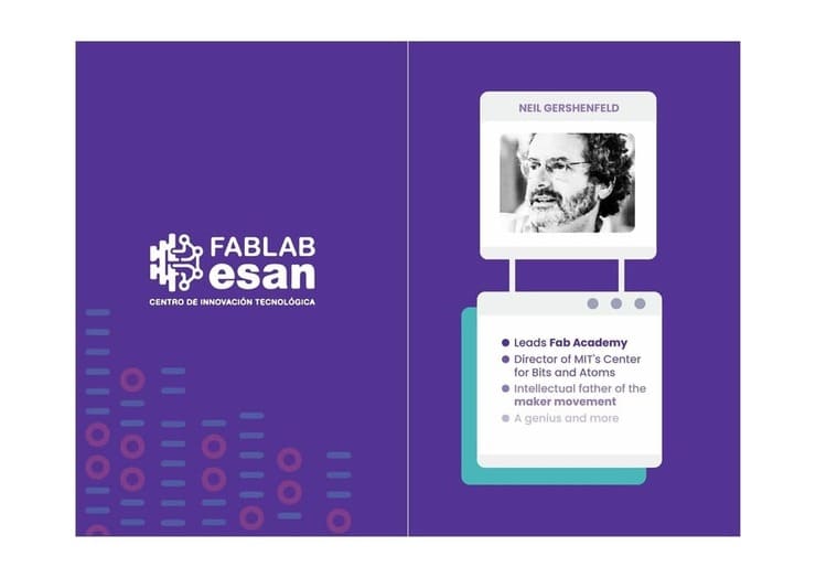
I used a picture from Neil Gershenfeld that I found on internet, I clicked on the
IMAGE TRACE, there are many options, I choseHigh quality pictureand finally I clicked onExpand. -
The image is automatically converted to vector, you can move it, ungroup it, delete any part you don’t like, edit it and group it again, in this case I left it like this.
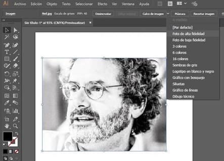
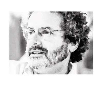
THIS IS THE VECTOR VERSION
DRAWING
Can I start drawing from scratch?
Yes, of course. You can make rectangles, circles, stars, and other shapes, combining them, joining them, subtracting them, etc. The program is very intuitive.
I could even say that it looks like other programs and you can use some similar options, which is great.
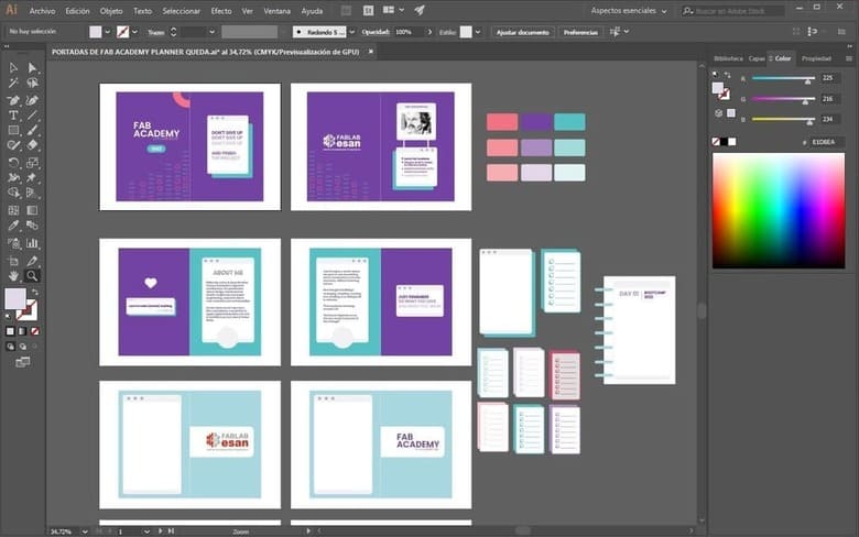
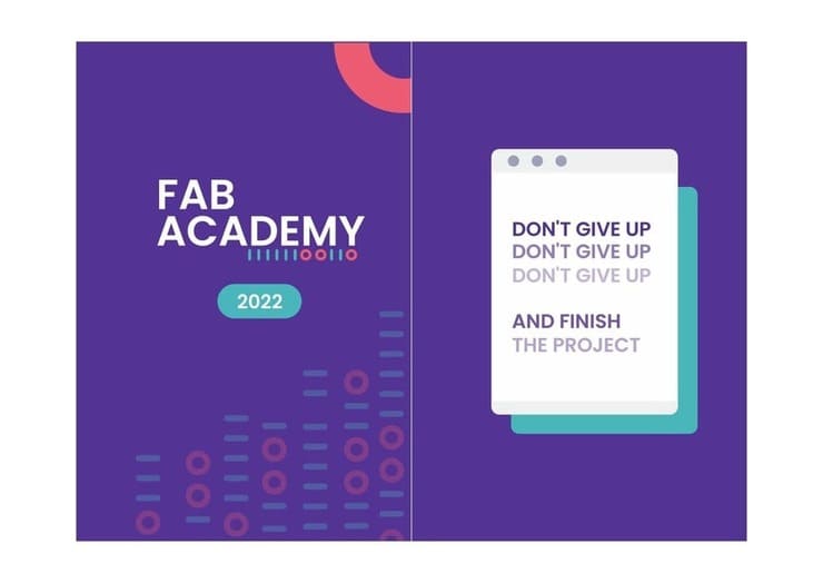
I tend to get very stressed if I don’t have everything in order, so I designed my disc planner, from the cover to the design of the inside dividers. To make my planner, I based it on the essence of the Fab Academy 2022 designs on social media. It is my Moodboard of reference:

I followed a Doméstika course that helped me to learn the program from scratch, I recommend it, ILLUSTRATOR - DOMÉSTIKA COURSE.
I vectorized the Fab Academy logo and drew rectangles and circles, modified the color, rounded the corners and size. That’s how I got my agenda design!
CONCLUSIONS:
You can make all kinds of shapes, including box shapes, flyer design, logos, etc. In addition, you can work with several work tables in the same file and you can modify each one as you wish, for me that makes the work much easier, it is even more practical than Photoshop (if you have a large project and want to see how everything looks together in your progress). You must configure well when saving your file, there are different formats, you can also export it in other formats such as png or jpg.
3. INKSCAPE
This is also a vectorization program and very similar to Illustrator, with similar tools but a different layout.
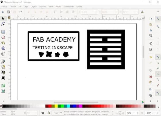
I drew some shapes with CIRCLE, RECTANGLE and POLYGONO tool, also the phrases with the TEXT tool, on the side, I placed a figure with a design that can be used for laser cutting and generating folds in the shape.
I prefer to work in Illustrator, I feel that the options are more intuitive, the new version of Inkscape is different from the one I saw in tutorials and certain results are relatively different.
When I tried to vectorize a logo and keep the colors in one step, it was not possible, even though I set it in colors, it has new tools and you have to configure everything well to get the quality you want. So I decided to vectorize in black and white a figure of an armadillo.
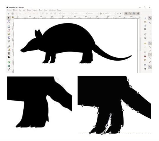
After vectorizing, you have to move the image above and separate it. Finally, you can make a DOUBLE CLICK on it and you can modify the internal points. I smoothed the corners with the tools at the top where the nodes come out. I saved the file in .SVG format to be able to open it in other 2d and 3d programs.
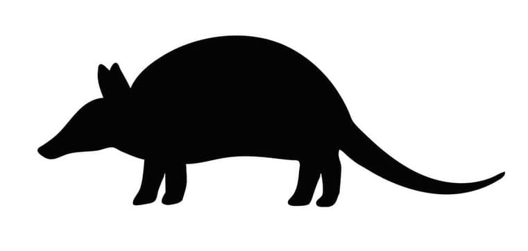
This is the result:
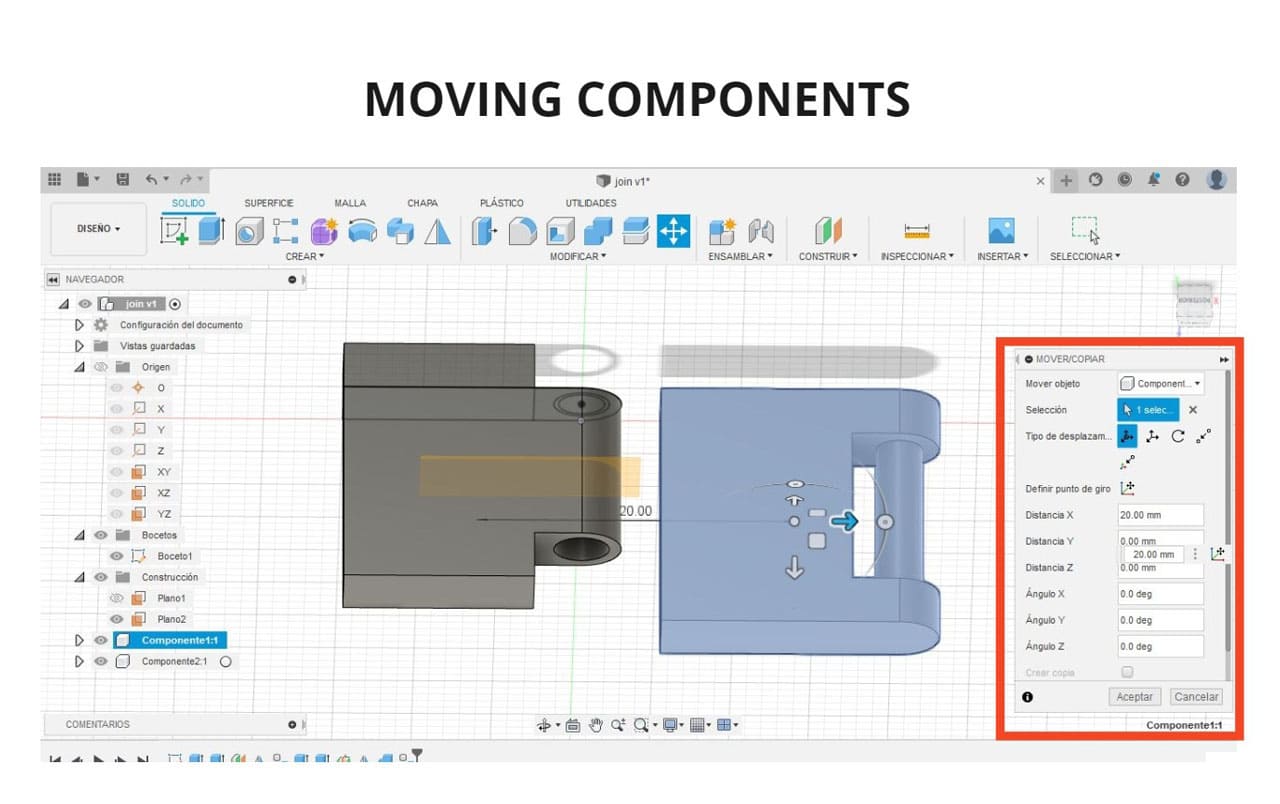
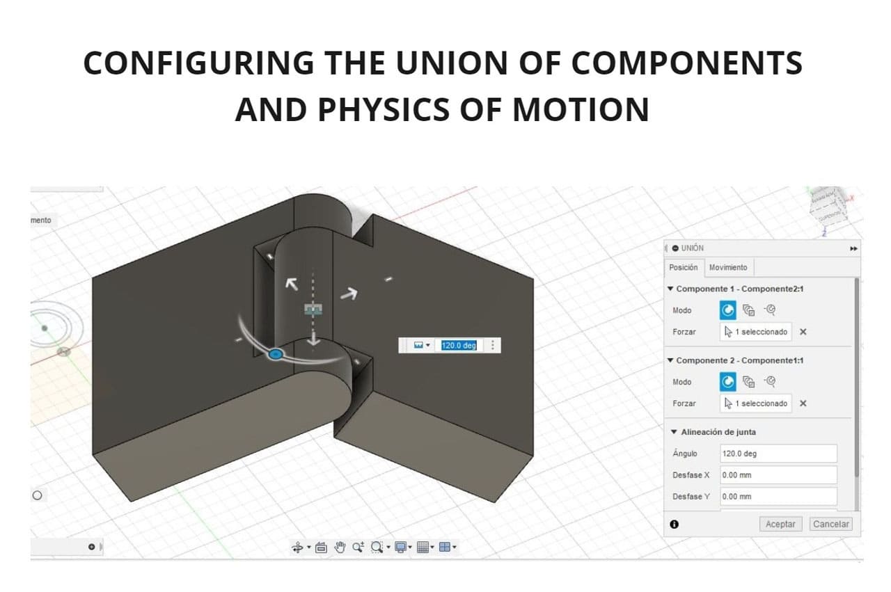
4. FUSION 360
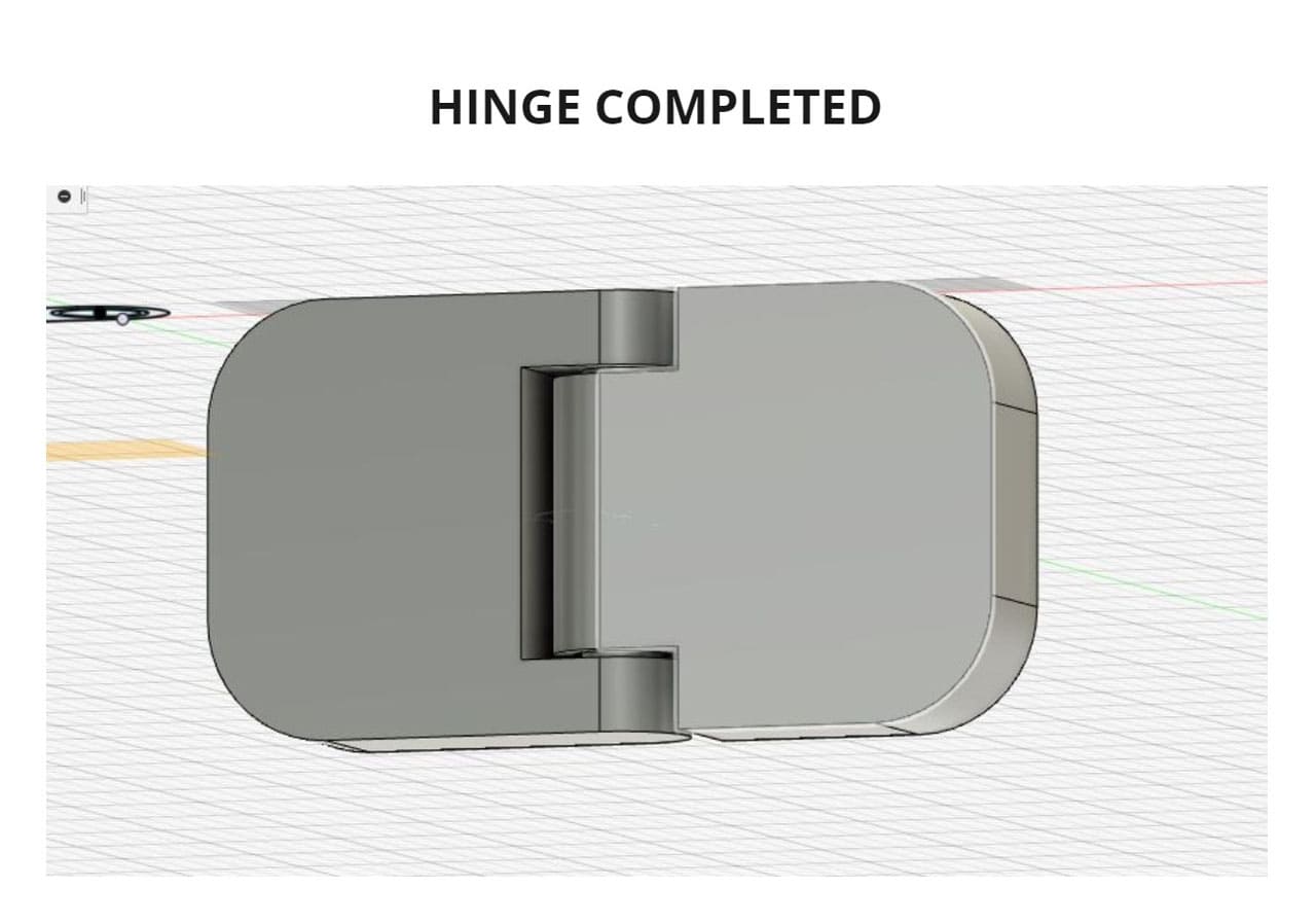
HINGES
The hinges will be an important part of my project, so I am starting from the basics, analyzing the movement and function to be able to modify and adapt it to my design.
We can create the hinge movement with two surfaces joined with this system, I find it interesting and useful in case you do not want to attach it to other surfaces, but they can work independently.
I followed this tutorial HINGE TUTORIAL.
This is only the first step, since I had to repeat it to learn how to use each command, you can see the process I performed and results in the following images:
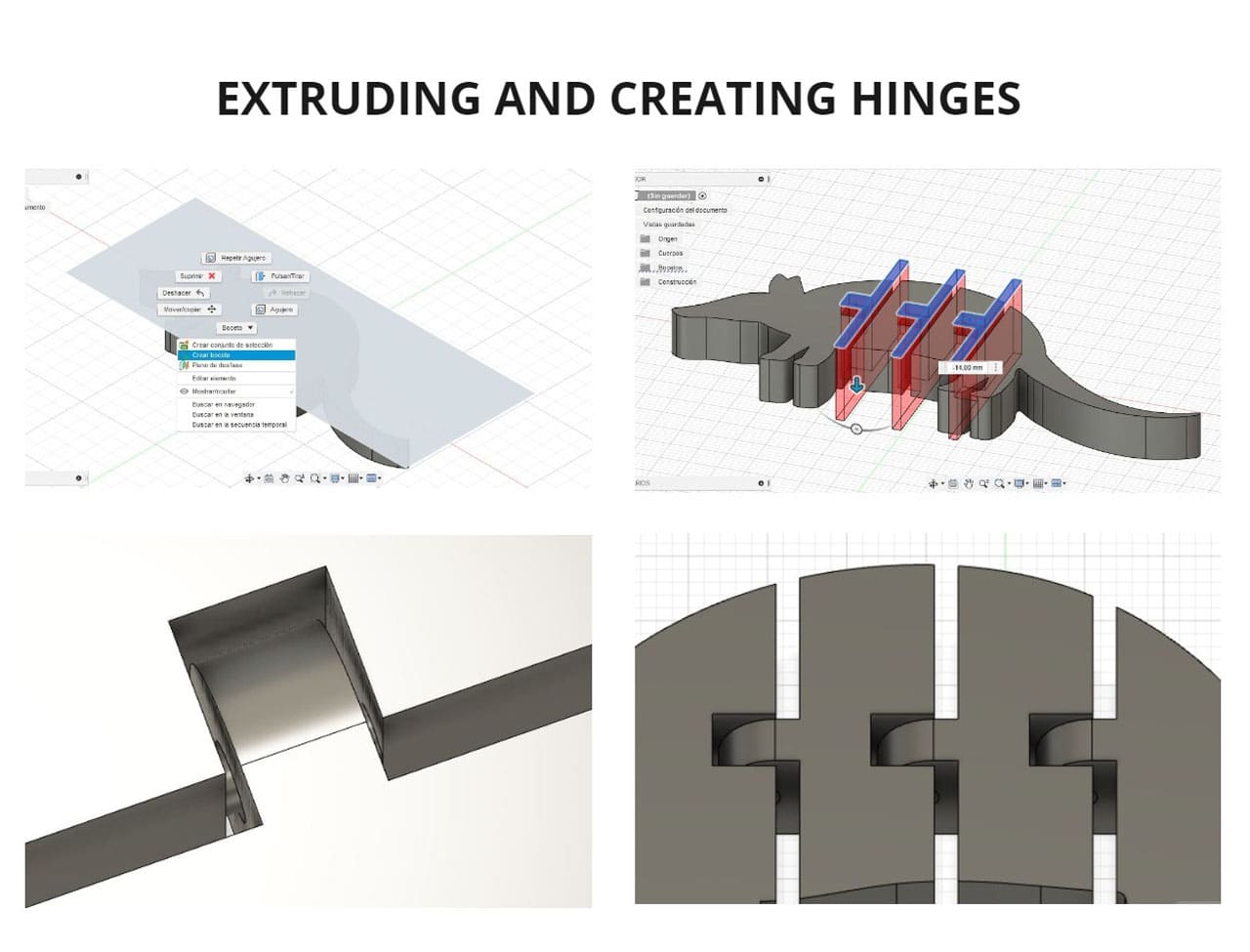
-
I used the
SKETCHtool and started drawing the geometry with theCIRCLEandRECTANGLEtools, I also used theCUTtool, to eliminate certain lines. -
I started to extrude and draw the rest of the geometries following the same steps.
-
It was designed in such a way, so that a body can rotate like a hinge.
-
Finally the
ENABLE ALL CONTACTtool was applied, so that both bodies are recognized and if you rotate, you will realize that they do not overlap, both rotate in a semicircular motion following physics. -
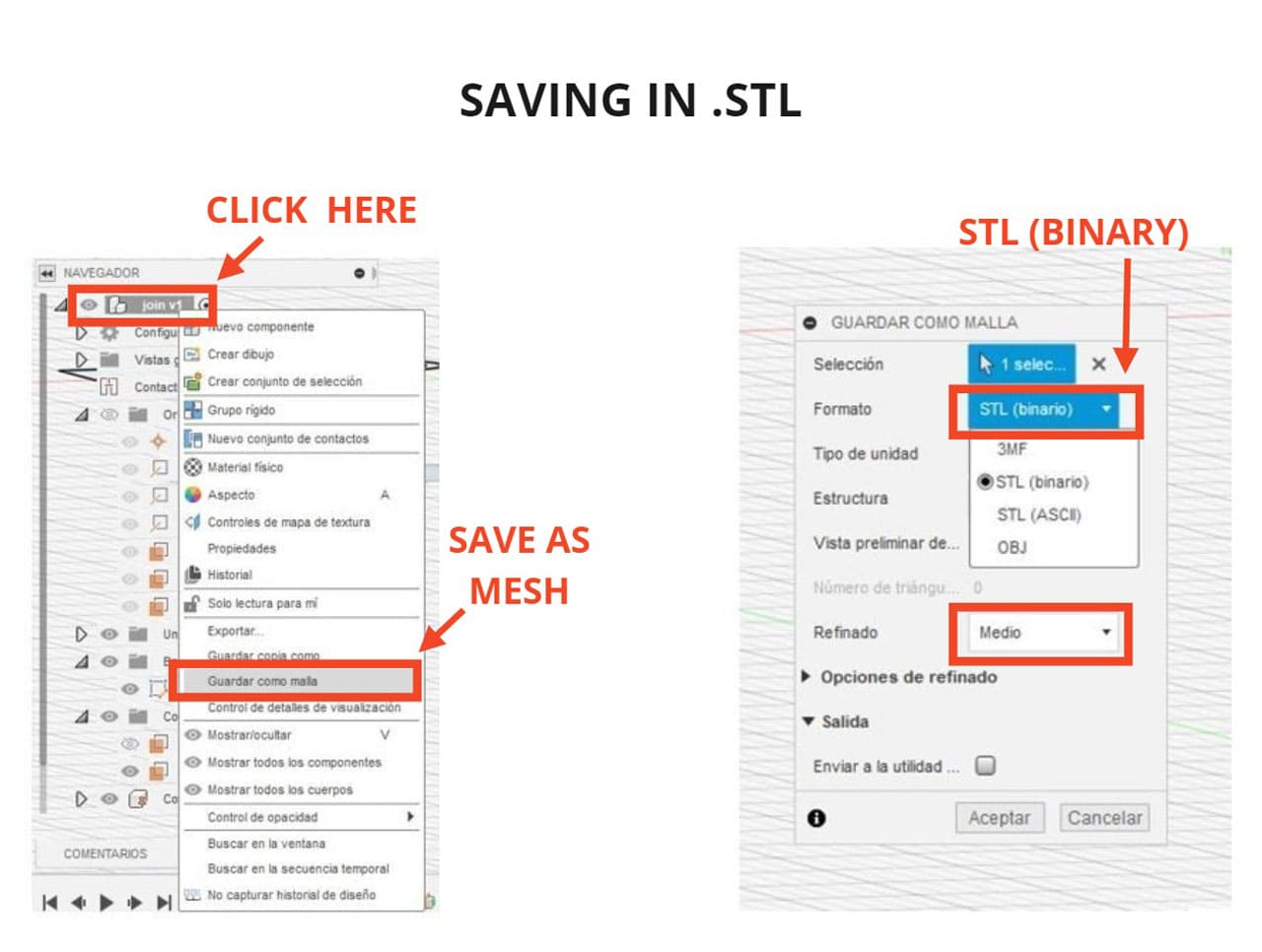
Finally, I saved the file in
.STL(binary).
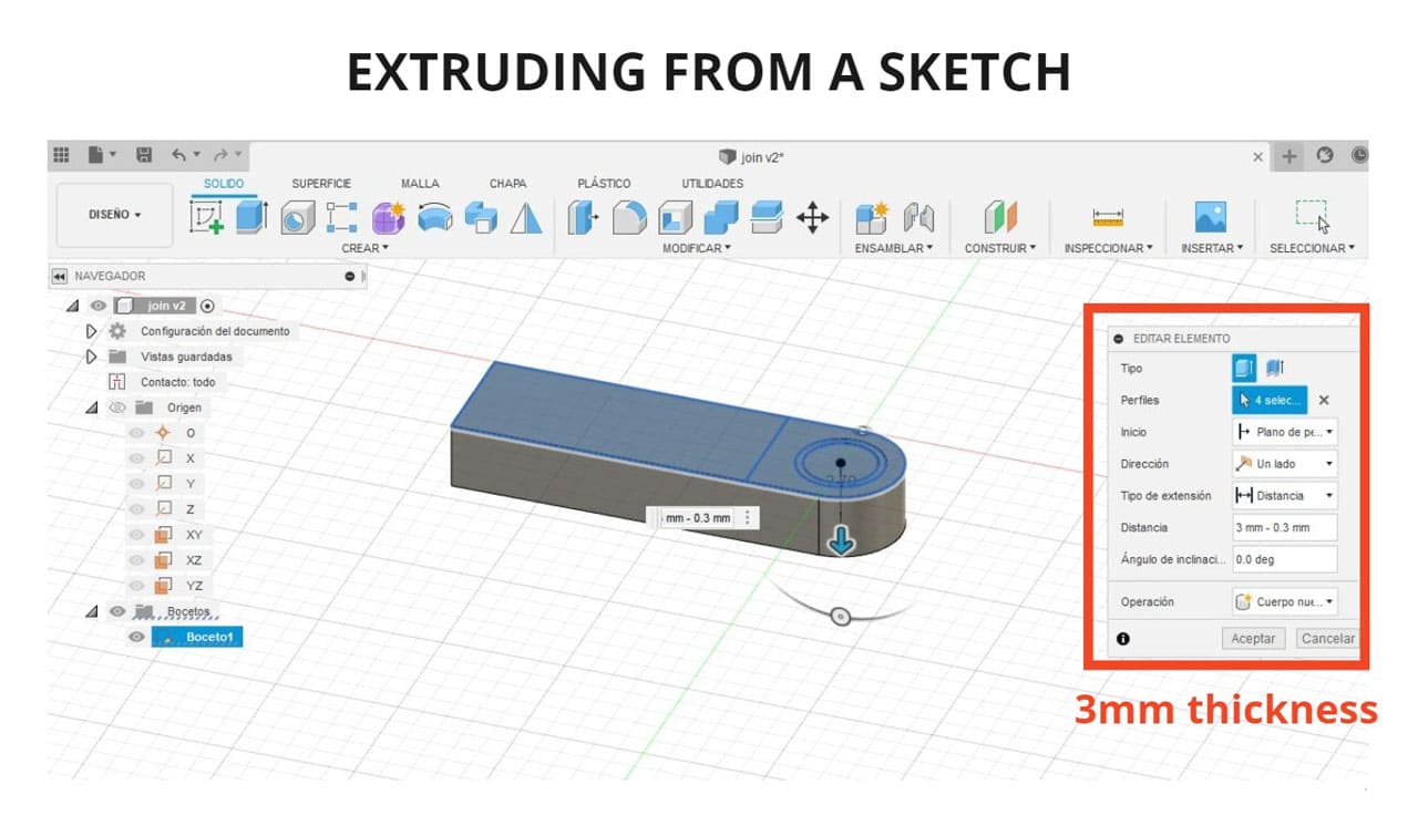
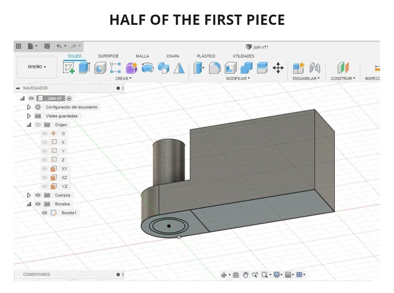
3D FLEXIBLE
Based on the hinge model, you can make the joints of a rigid element and make it flexible.
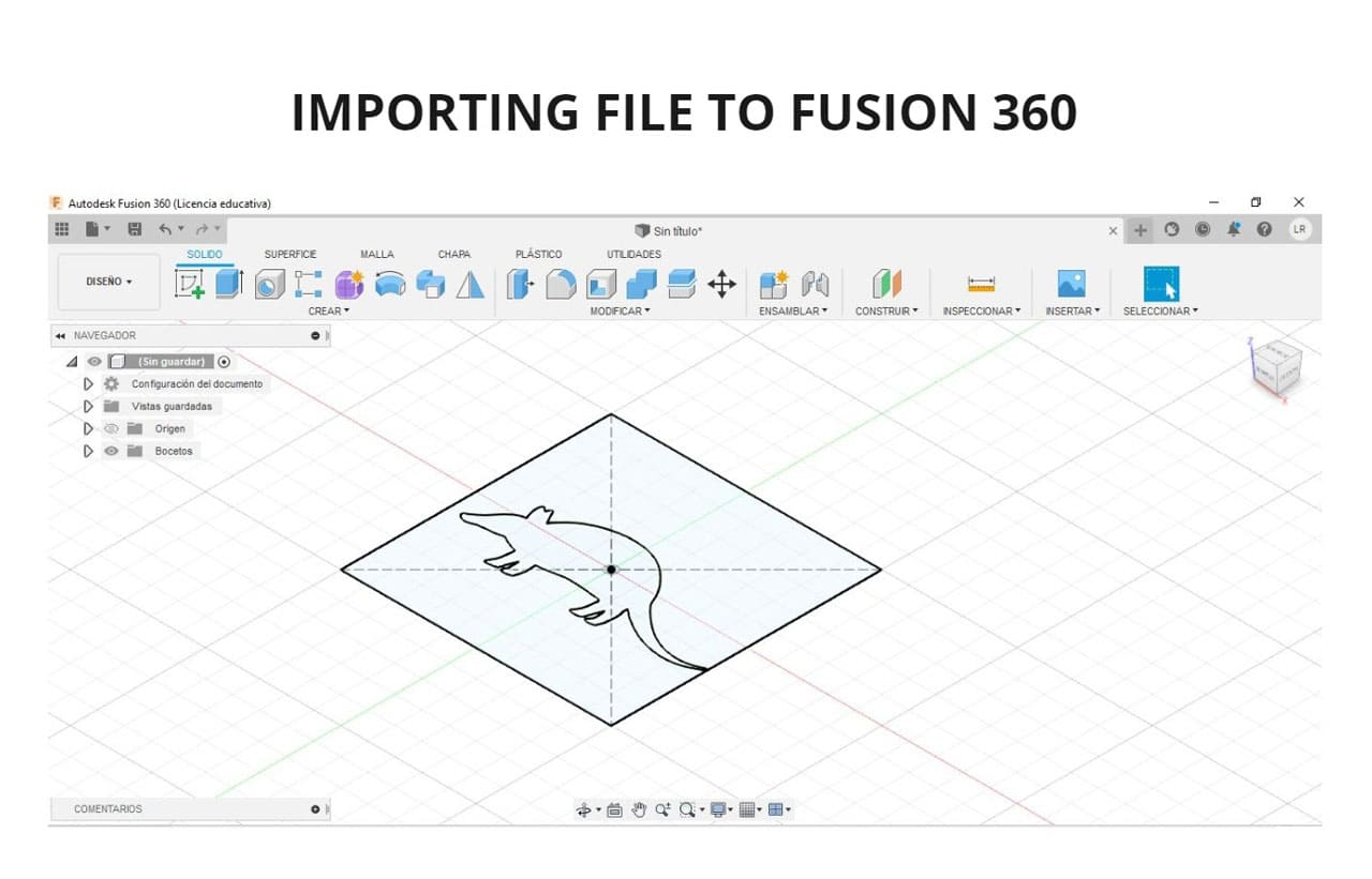
In this case, to make it faster,I used two programs, use the image of an animal and vectorize its outline in Inkscape, then save it in .SVG format and open it in Fusion 360.
I followed similar steps with the same logic as the previous example on HINGES.
But this time with the figure of an animal and with more independent bodies.
You can see the process in the following images and the result:
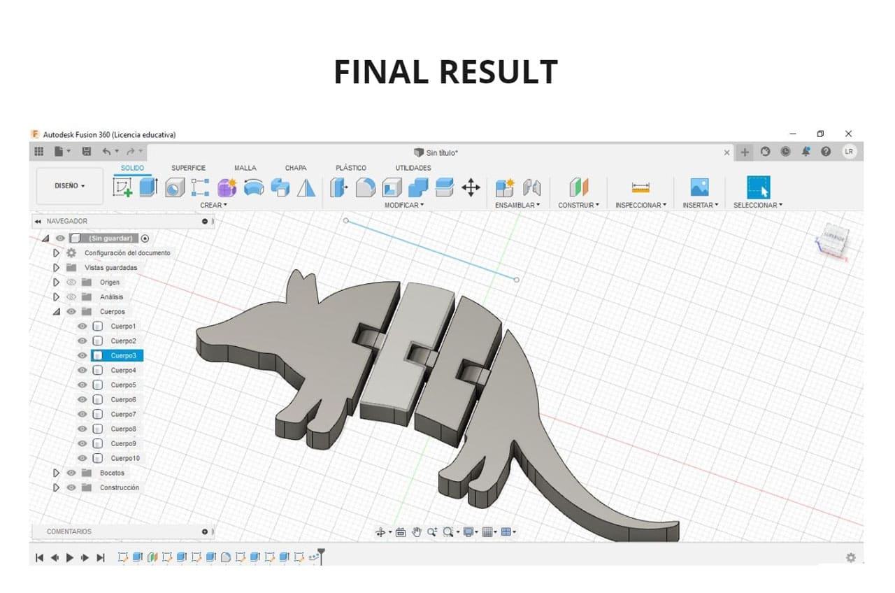
Then you can save it in Fusion 360. You can also save it in a format suitable for 3d printing (depending on the printer you have) but .STL and .OBJ are the most recommended.
I liked to make this because it can be very useful for 3d printing without supports (to avoid problems in the joints), this 3d armadillo consists of 4 pieces joined with a hinge mechanism and once printed, it can be moved (I hope to print it in the 3d printing week).
I find this type of joint interesting, I believe that it is possible to work this way the axes of rotation of my project, with small modifications in the internal corners of each piece.
5. SLICER FOR FUSION 360
You can make any 3d part to have results of segmented parts in many ways, they can have a 90° order or with radial axes. I love to experiment with this tool. So, I will use it with an animal which is one of the most organic shapes that you can find in nature.
The design I chose is very sculptural and it is much easier to develop it in a program like Blender.
In this case, I went to the Thingverse website, which is a page where the maker community uploads their projects:
I followed this tutorial to get a better command of the program, SLICER TUTORIAL
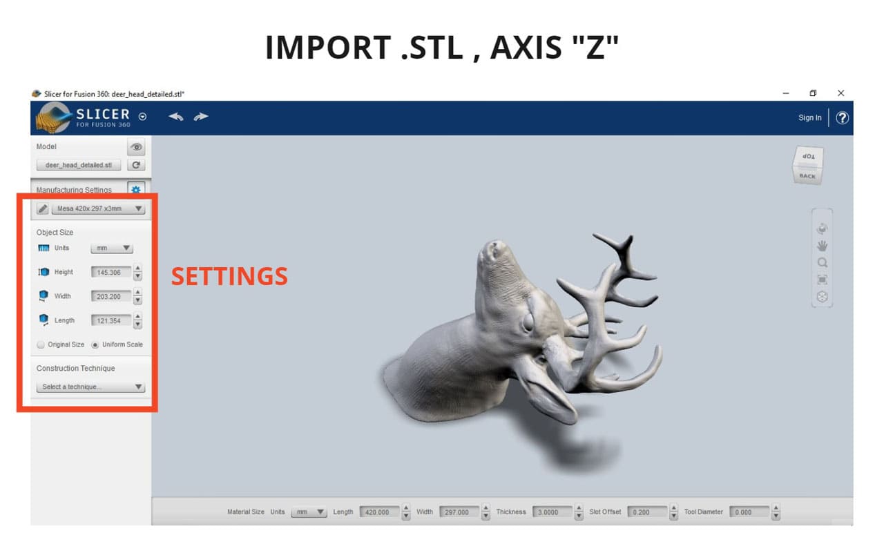
Slicer for Fusion 360 is compatible with .STL and .OBJ files, so as long as the files are in those formats, we can open them in this program.
-
I opened the program and chose the
IMPORToption, click on.STLfile and choose and axis, in this case I click onZ. -
Choosing the axis is important, as it is the head of an animal and it will be attached to a wall, I decided that this part should go in the direction of the floor.
-
You can choose the size of the tables where the pieces of the figure will be placed. I chose to set them in
A3 sizebut not using the current option, I created a new one in millimeters. -
You can change the number of segments that it has. Also, you can rotate the direction of the pieces without the general shape since the shape of the deer is still seen.
-
You can scale the figure proportionally if you want a larger or smaller size in the
OBJECT SIZEarea.
The dimensions of the work table to be used are modified according to the dimensions of the material, for example, if a Mdf panel is 300x600mm and 3mm thick, these would be the dimensions to be configured.
I added a new material and named it MESA 420x297x3mm.
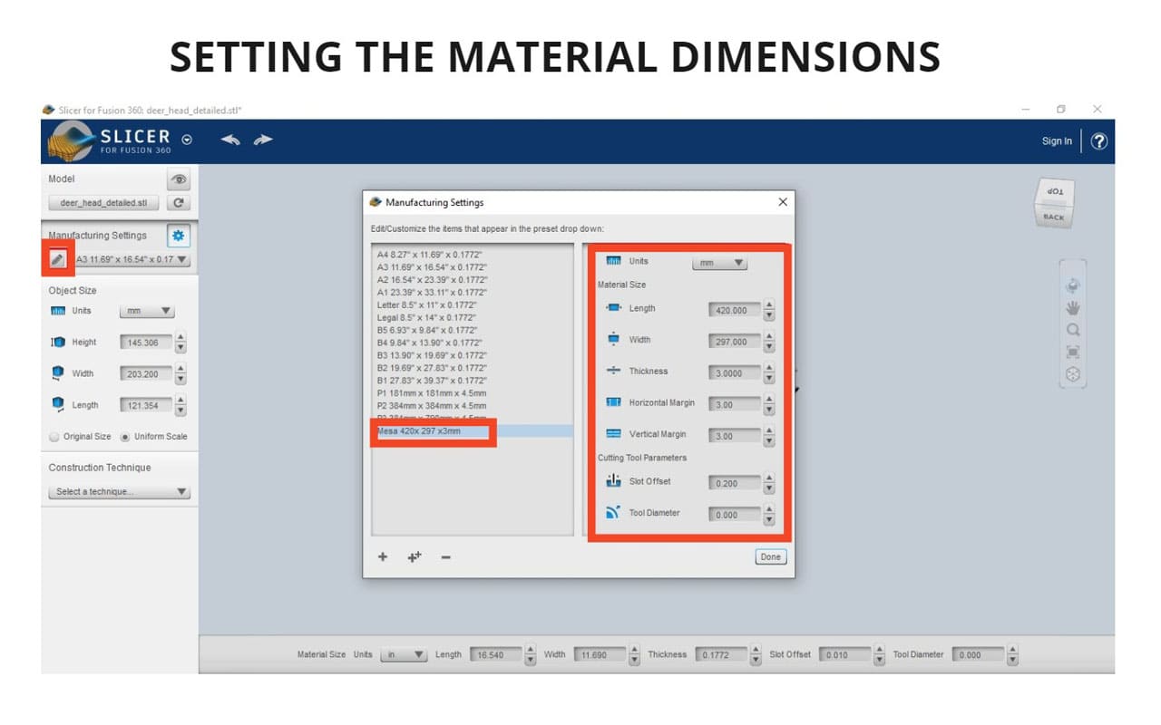
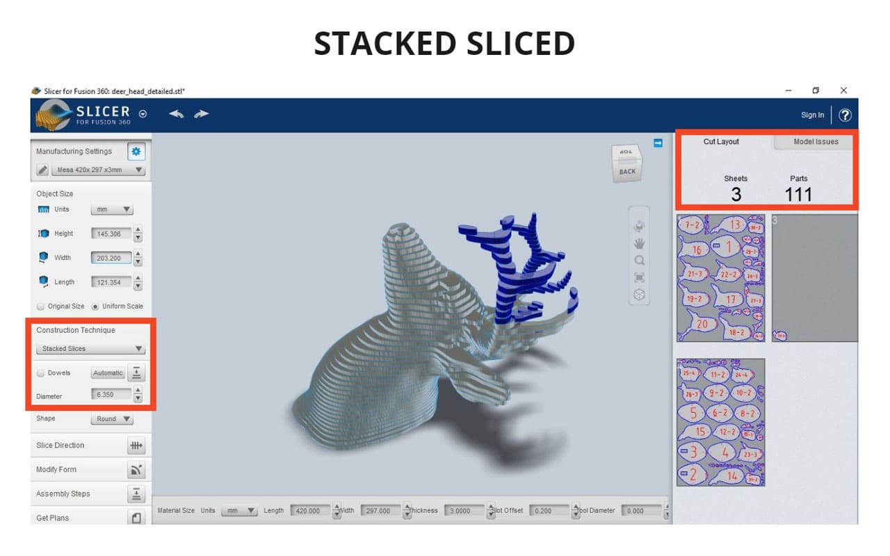
The parameters I used for the first design were:
-
Construction technique: Stacked sliced
-
Diameter: 6.350
I did not modify the other parameters. On the right side you can see how many sheets of the material are needed for the pieces, in this case:
-
Sheets: 3
-
Parts: 111
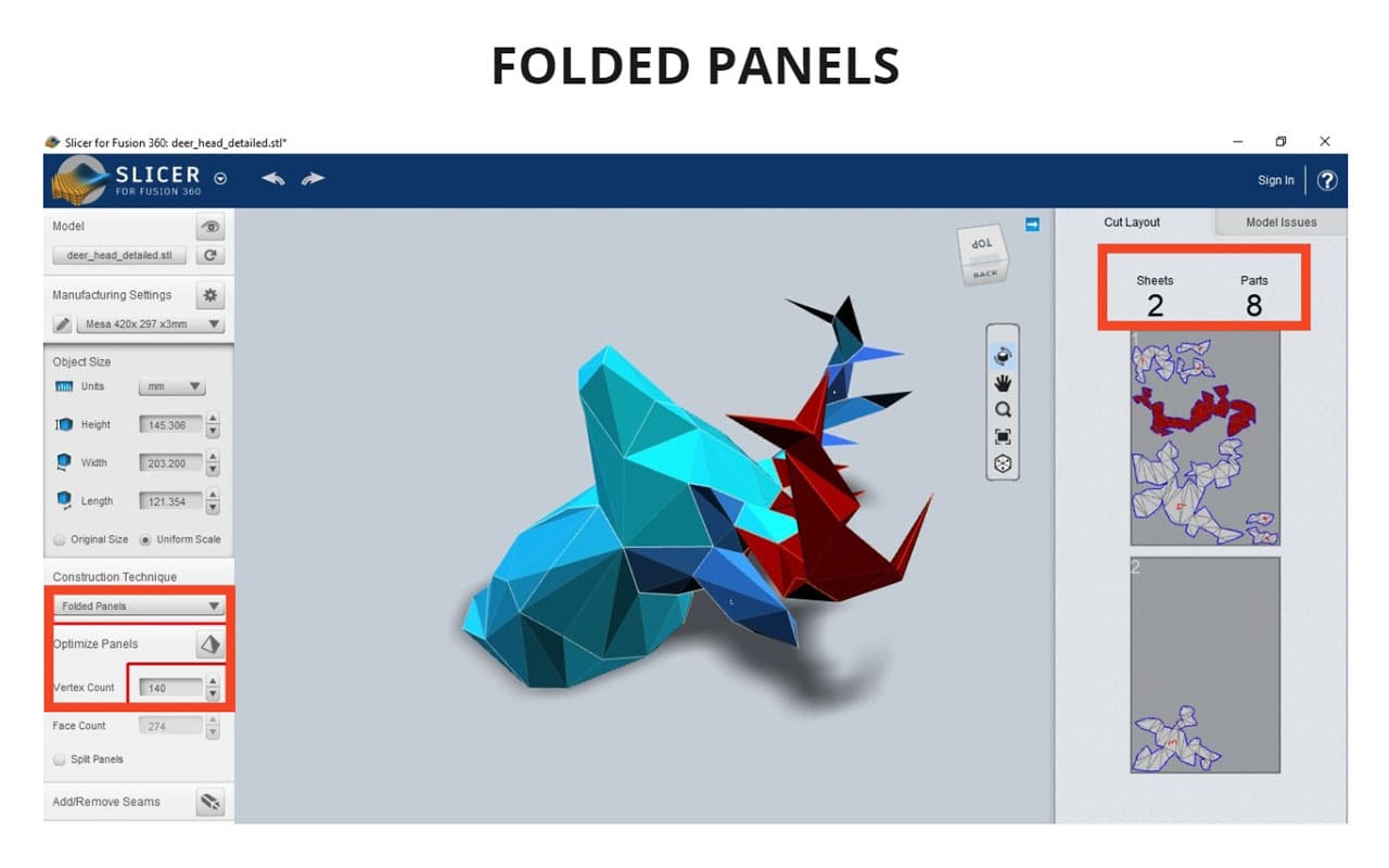
The parameters I used for the second design were:
-
Construction technique: Folded panels
-
Vertex count: 140
I did not modify the other parameters. On the right side you can see how many sheets of the material are needed for the pieces, in this case:
-
Sheets: 2
-
Parts: 8
The program itself indicates it your work table is too small for your pieces, these appear in red and indicate an error.
You can reduce the design so that it can fit inside the work table or use a material with larger dimensions(a bigger work table).
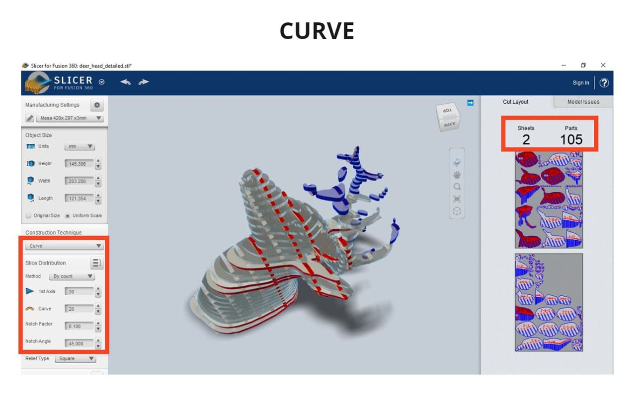
The parameters I used for the third design were:
-
Construction technique: Curve
-
1st axis: 30
-
Curve: 20
-
North angle: 45
I did not modify the other parameters. On the right side you can see how many sheets of the material are needed for the pieces, in this case:
-
Sheets: 2
-
Parts: 105
Something that is very helpful in Slicer, are those annotations indicating the part number and with which other parts are assembled.
You can also save your file in your Fusion team or on your computer, which is great for teamwork (Fusion team).
Something you have to keep in mind is Save the file in the default folder, if you save it in another folder, you will have problems. It has already happened to me when I tried to saved in other folders. The file can be saved in .stl , .obj and .3dmk formats.
CONCLUSIONS:
It would be very useful to be able to pass figures made with low poly or work the cutting of parts in cnc (depending on the design we choose to do). I love this program, I have seen this type of structure done in other programs, but it was a bit more complex to do it. Instead, here it is much easier, practical, intuitive, you can navigate through all the tools and try each one.
6. TIPS AND RECOMENDATIONS
If you are working on more than one pc or laptop, always keep a backup on a USB. This week my pc stopped responding, on Sunday to be exact and my documentation and files just sat there. Please be more cautious than me!
The graphics card in my desktop computer stopped working and I had to go back to using my laptop, the problem is that my laptop does not support the use of heavy programs, it can limit me.
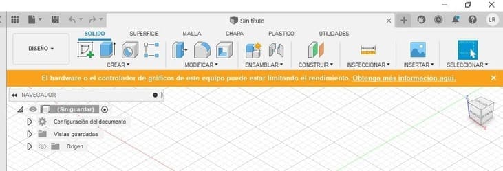
As soon as I opened the Fusion 360 program on my laptop, an orange notice popped up The hardware or graphics driver on this computer may be limiting performance. But there is a shortage of it, I hope to buy a new graphics card before the weekend.
7. WHAT I LEARNED THIS WEEK?
-
I experimented a lot of fun with Fusion and Slicer for Fusion 360, as well as 2d programs. I realized that in both (2d and 3d) I can do animations and simulations.
-
I managed to make the HINGE rotate without merging the volumes, that is to say that they recognized each other and their limits.
-
I find it very interesting to use these programs to design proposals of all kinds, from the creation of a product, prototyping, model for animation, etc.
-
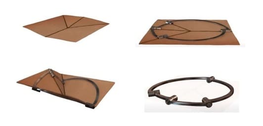
Based on what I have learned this week I am already projecting what I will do next week, I will try to make origami with the parts of my design and then replace the joints with hinges and place metal brackets as it is much easier to work with. I will also make joints that can be bent just by laser cutting next week, to make them look as aesthetically pleasing as possible (I saw this method has already been used and worked very well). Example: