Final Project
Week 0: Digital Fabrication Principles and
Practices
Week 1:
Collaborative Technical Development, Documentation and Project
Management
Week 2:
Computer Aided Design
Week 3:
Computer Controlled Cutting
Week 4:
Electronics Production
Week 5:
3D Scanning and Printing
Week 6:
Electronics Design
Week 7:
Moulding and Casting
Week 8:
Embedded Programming
Week 9:
Computer Controlled Machining
Week 10:
Input Devices
Week 11:
Composites
Week 12:
Interface and Application Programming
Week 13:
Output Devices
Week 14:
Networking and Communications
Week 15:
Mechanical Design and Machine Design
Week 16:
Applications and Implications
Week 17:
Invention, Intellectual Property and Income
Week 18:
Project Development
Week 19:
Final Project Presentation
|
Final Project:
Finally
the projected is completed! This project provided me with a lot of
fustrating experiences, particularly with the internal parts of the
project, but through perserverance I have completed the first iteration
of the project. The project covers skills from various different
topics definied in the Fab Lab syallabus and teaching schedule, these
are: Computer Aided
Design, Manufacturing and Modelling, Electronics Production, 3D
Scanning and Printing, Electronics Design, Embedded Programming, Input
Devices, Interface and Application Programming, Networking and
Communications.
Through, my experiences in the final project, I ended up using a
'spiral development'. Instead of primarily using one large system
(that I had ultitised initially). I broke the development of the
electronics into a series of sequentially manageable sections from
previous sections of the Fab Academy schedule Thereby, I created
smaller boards that performed a single defined role that could be
networked together in sequence.
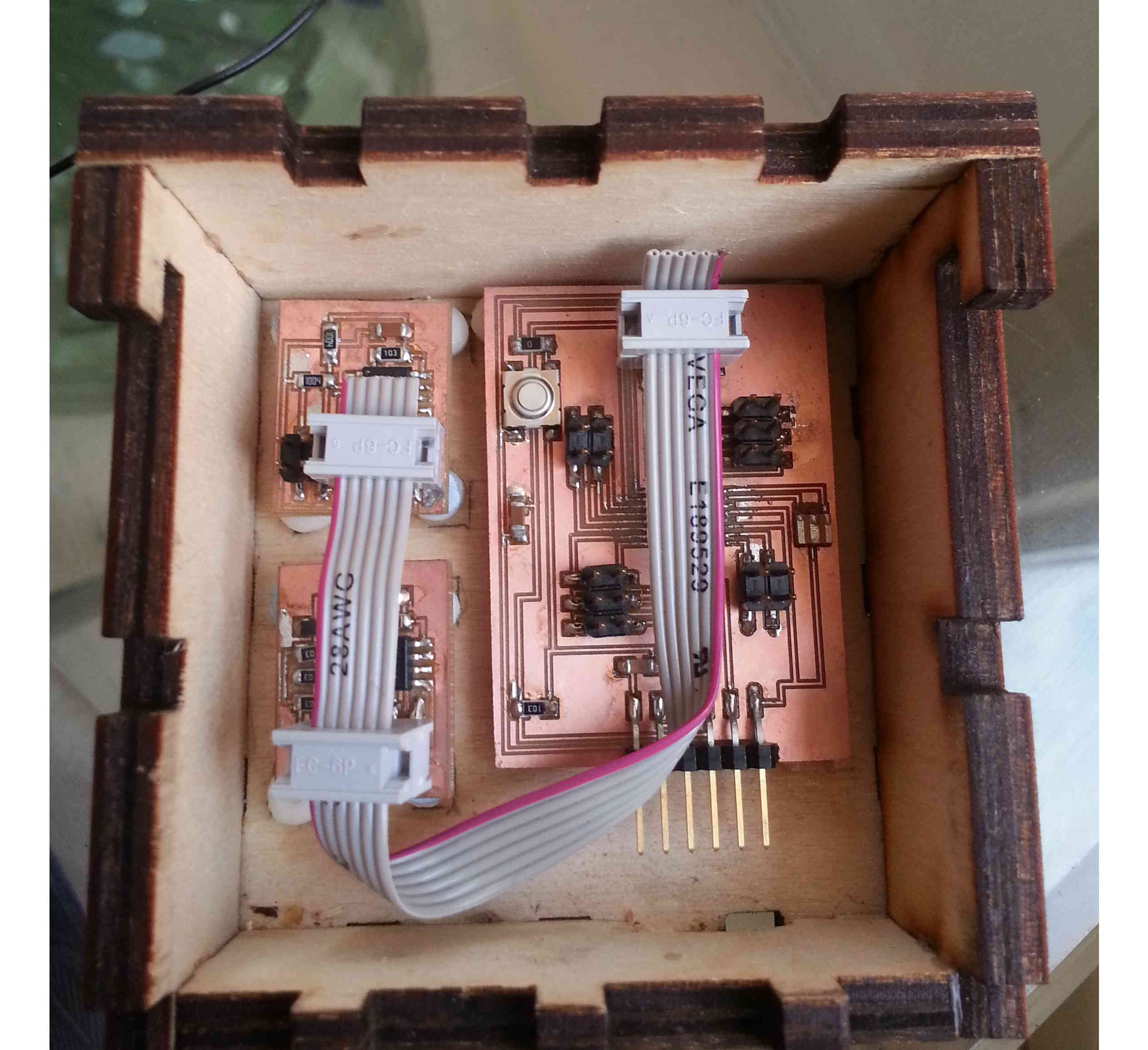
Electronics rationale/Embedded Programming Part 2:
The internal
operation of the system is driven with attiny44 microcontrollers, with
firmware written in C. The boards are based on the designs shown
within the Fab Academy schedule i.e. Temperature Sensor, Transmit
Receive Sensor and Hello Arduino board. The basic input boards
include an attiny44, ISP header, 10k resistor pulling RST high, power
capacitor. The controller board was driven by atmega 328
microcontroller, with jumpers for all the output pins.
Board Two - Temperature Sensor:
The code for the temperature board is almost entirely lifted from the
temperature sensor code for the input section of the Fab Academy and
included the bit-banging code from the hello.bus.45 example. So this
microcontroller waits for a transmission from the Controller board
before reporting a reader from the board. Using the FTDI 6 pin
jumper breakout board I made in the previous week I debugged the
Temperature Sensor.
Board Three - Moisture Sensor:
So
by this stage I had a working Temperature sensor board working. The
next thing I wanted to do ensure that the moisture sensor board worked
seperately and in conjunction with the temperature board and it was
properly calibrated to sense moisture in a piece of timber. The
connection can only be achieved once the controller board is up and
running.
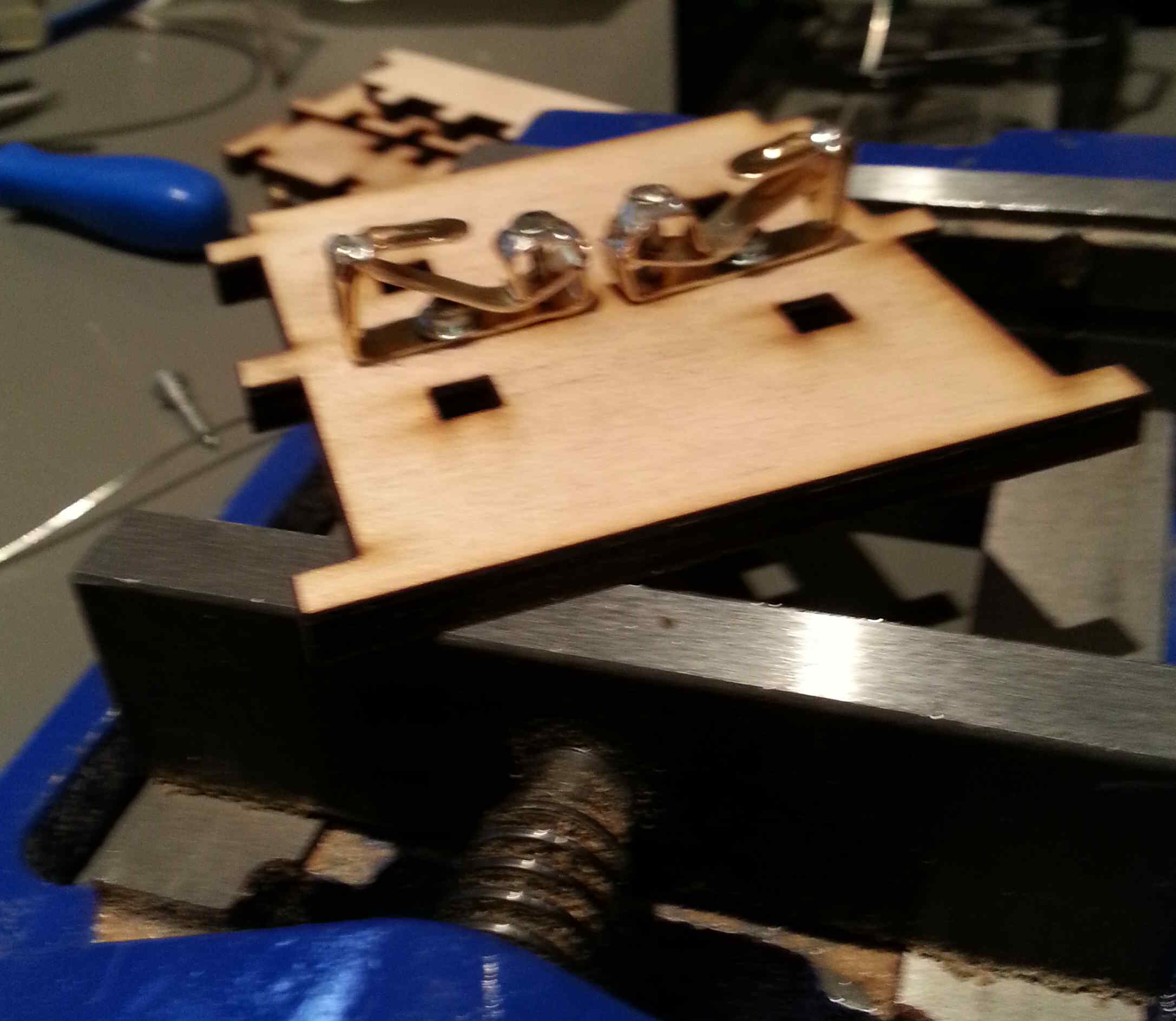
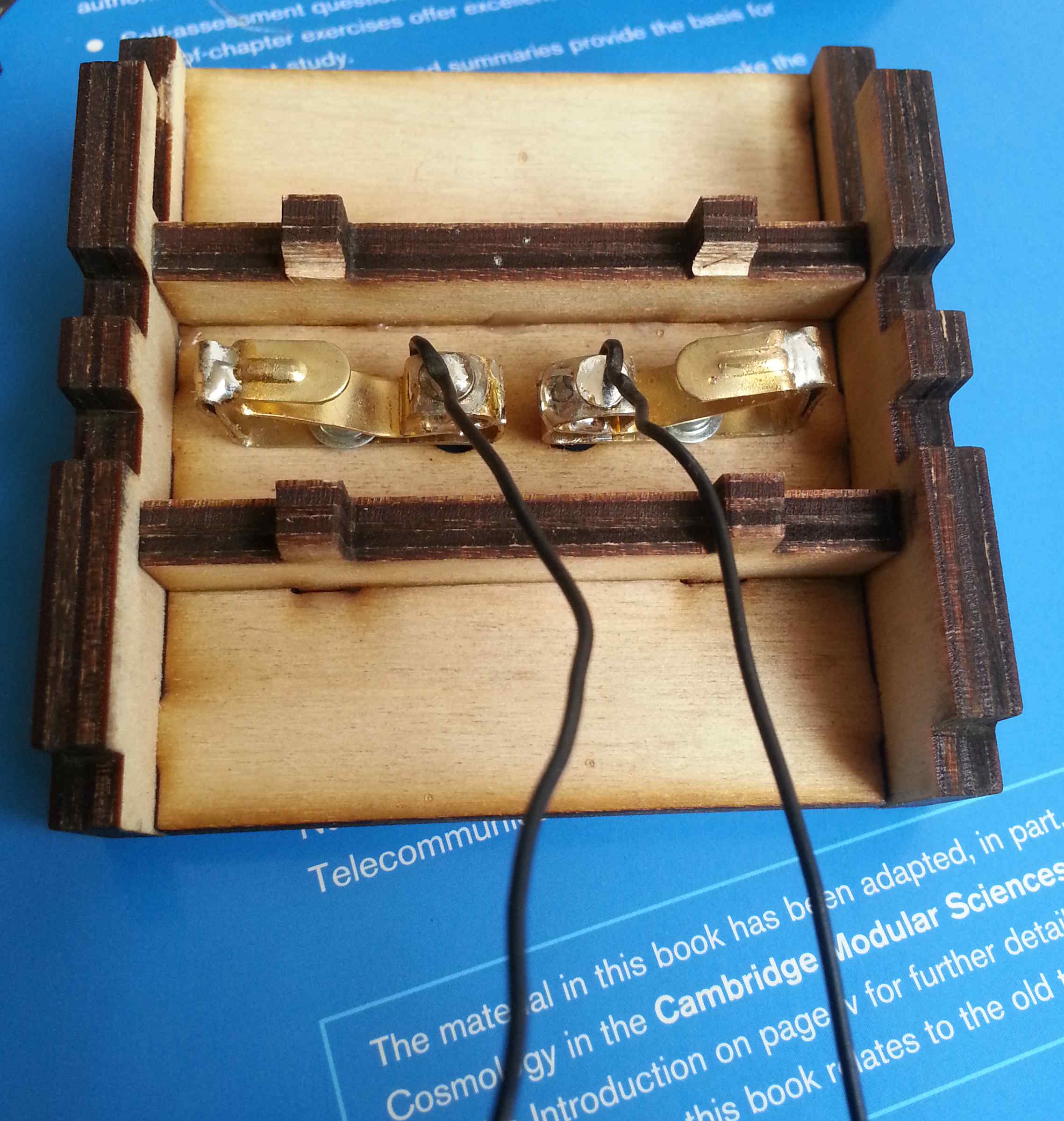
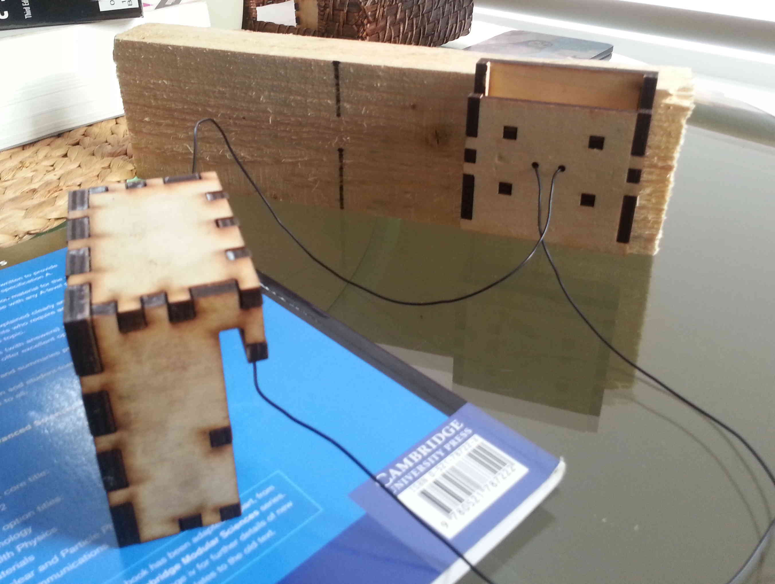
Sensor Prongs - Moisture Sensor:
I developed the sensor prongs using a combination of bits from a
hardware store, this included nails and picture hangers to locate and
support the prongs - Once this was achieved I soldered wires on to the
prongs and tested with moisture board. Calibration of the values
is achieved through the Python application previously given to us in
the input section of the Fab Lab schedule. It should be noted
that the available copperboard available in the lab was double sided, I
found during the calibration process that the resistance or
transmittance of the copper on the underside of the board effect the
values greatly and would not allow a steady reading to take
place. I had to manually scrape off the copper on the underside
using a scalpel.
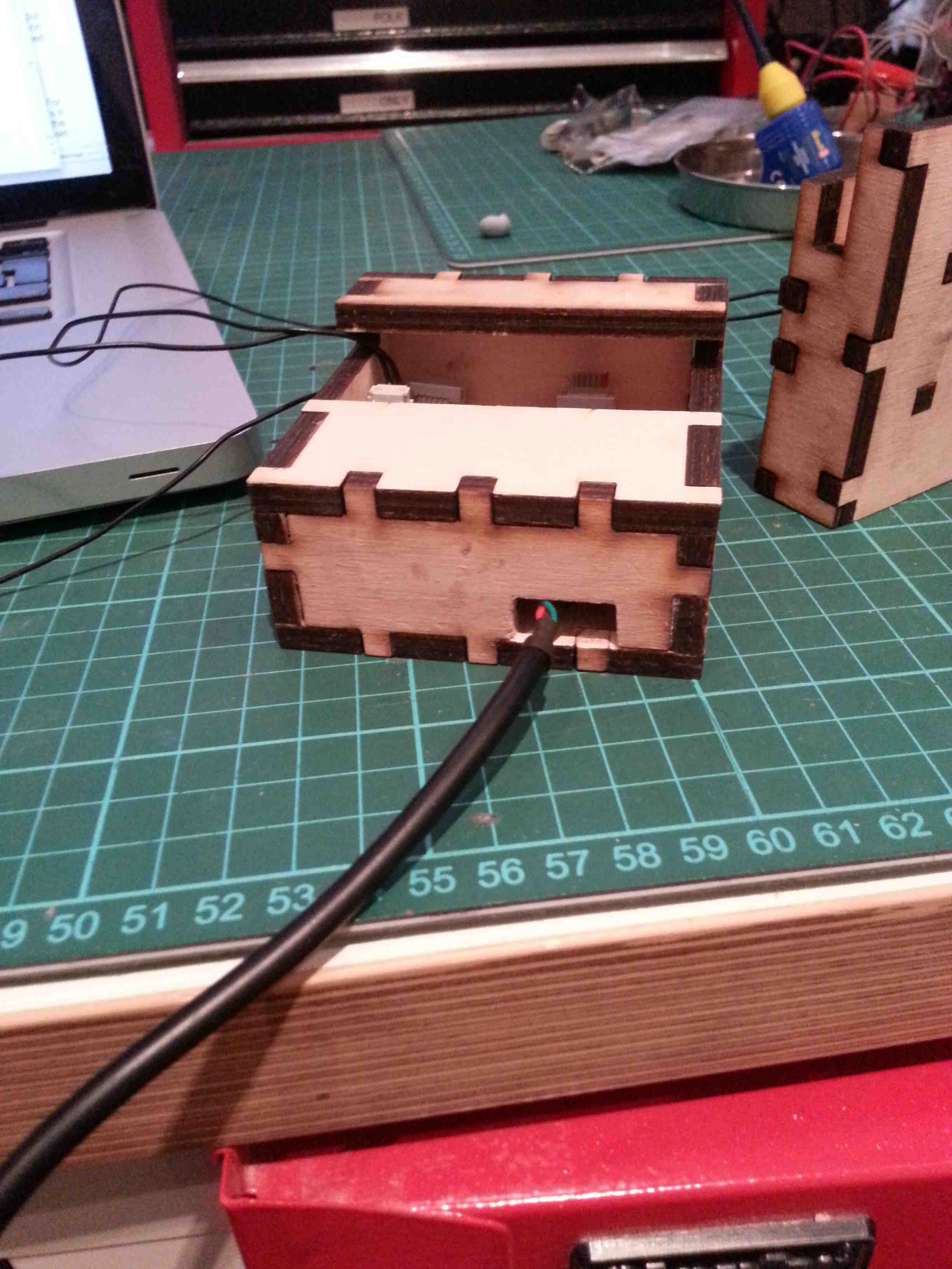
Board One - Controller:
The first board
was initally
conceived to connect to the computer wirelessly but due to time
constraints and lack of knowledge I was unable to intergrate this into
the first iteration of the project. Therefore the controller
board
connects directly to the host computer via an FTDI cable, it sends and
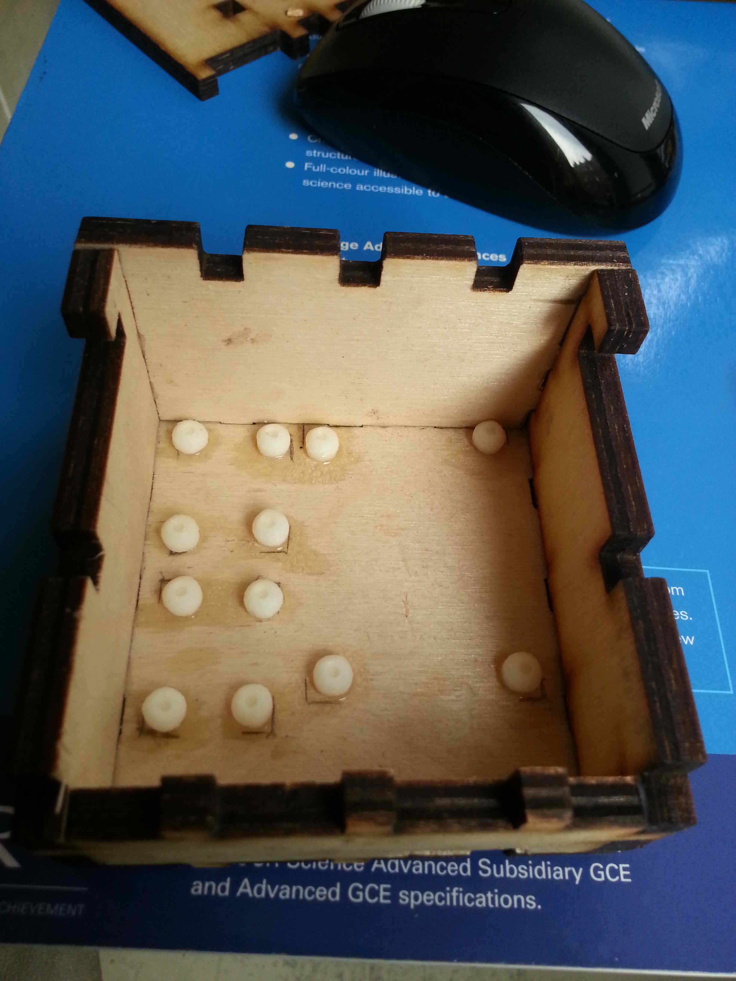
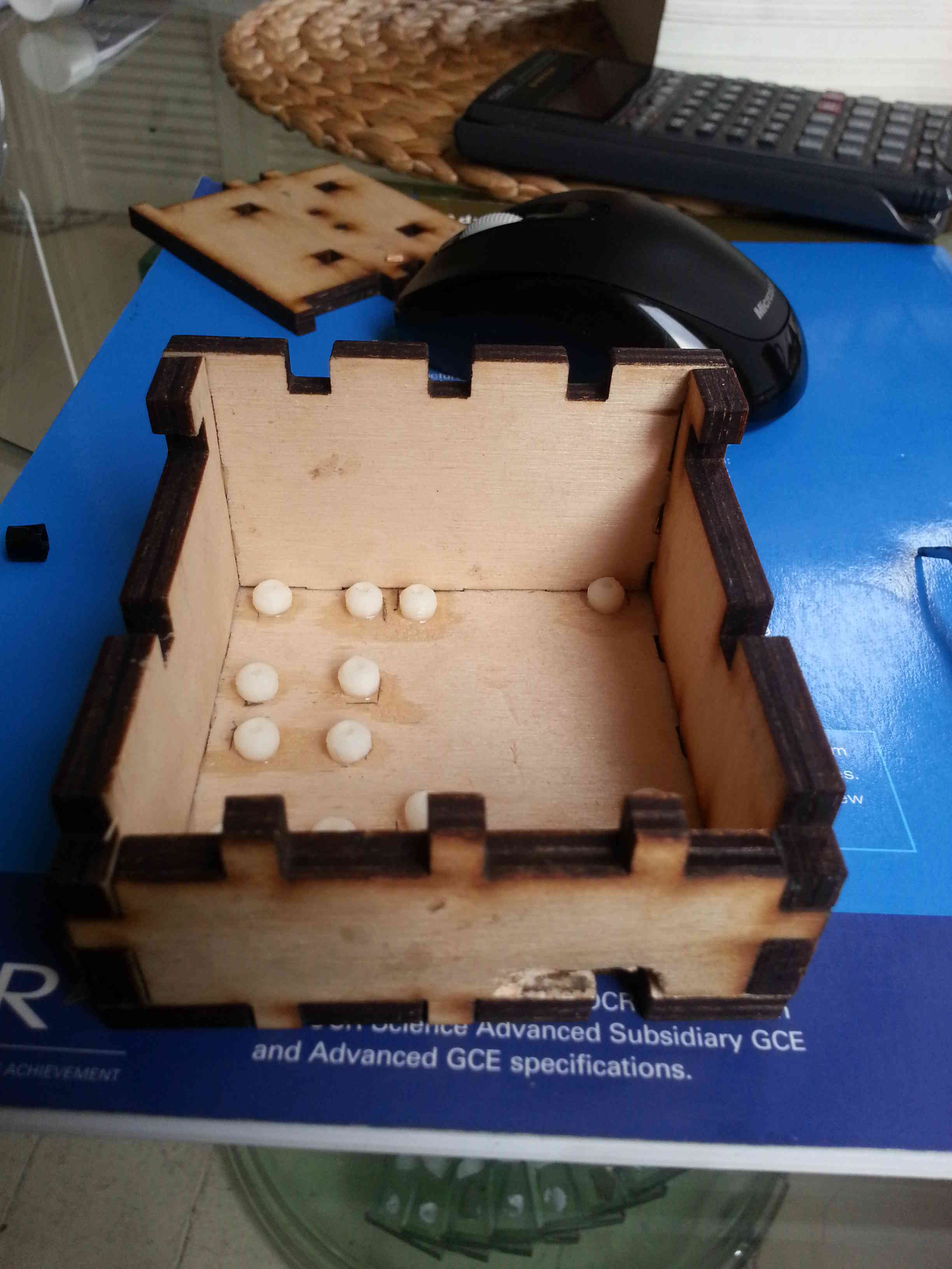
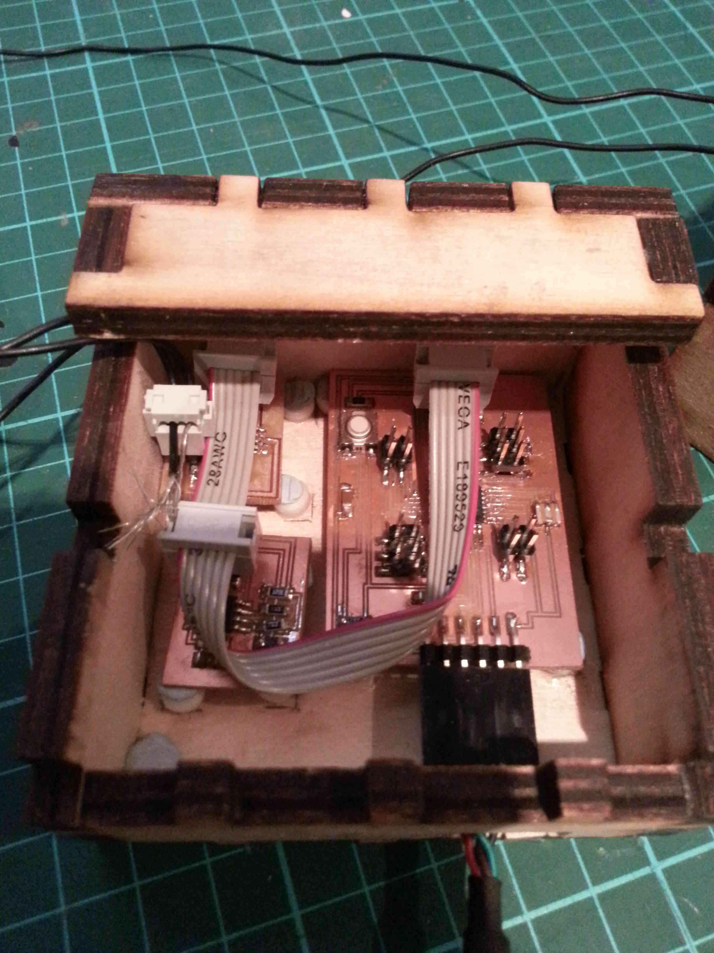
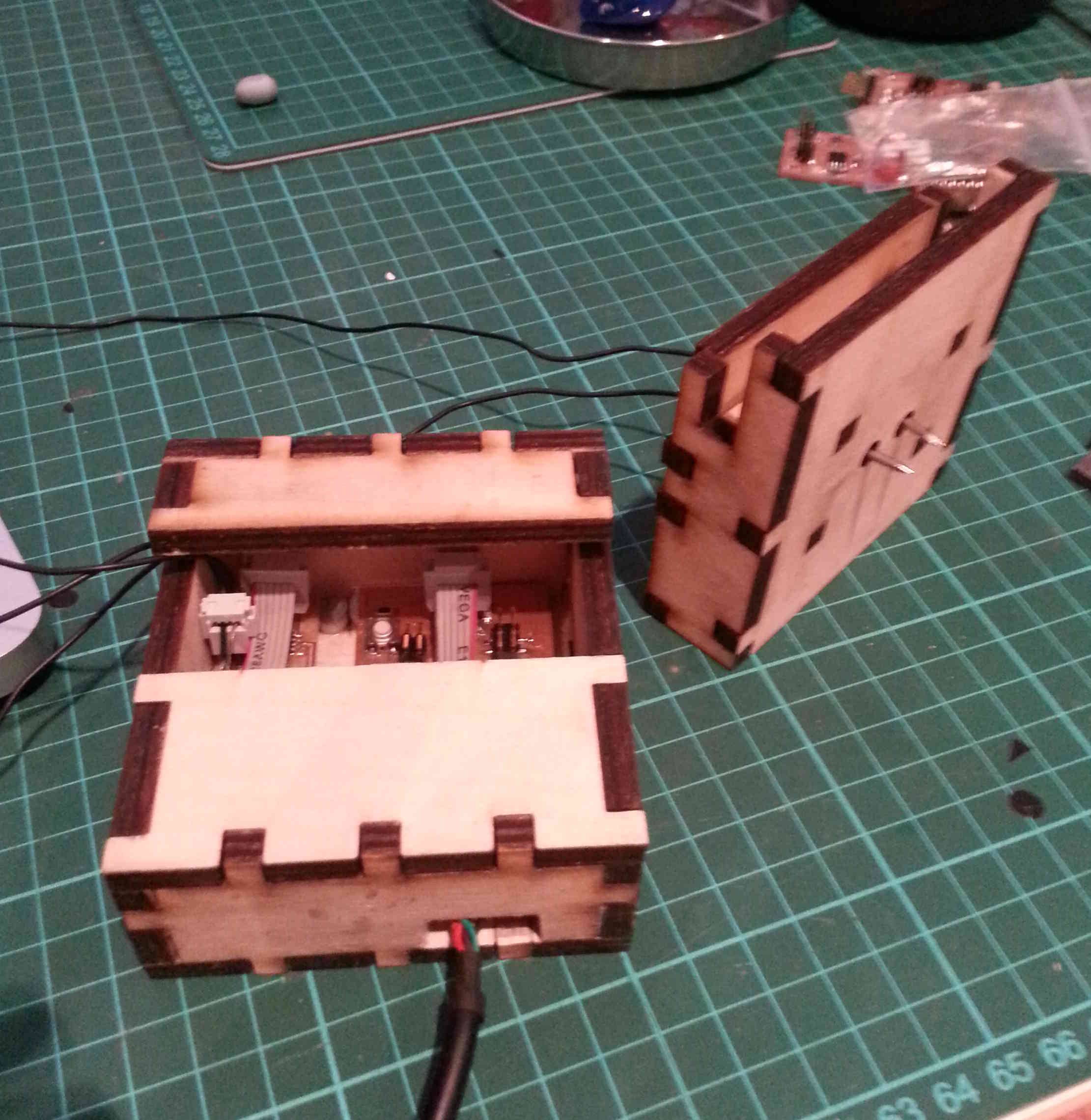
receives serial messages from the input boards. Unfortunately the
case I had previously designed didn't accomodate the FTDI connection
and with the larger footprint of the three seperate circuit boards, I
had to modify the case to allow this connection to be secured and
function correctly. This crude arrangement will be improved in further iterations.
Once all the boards were linked using ribbon cables to the ISP jumpers,
I had to develop the controller board code. This proved to be the most
difficult of the whole project as I found it incredibly difficult to
find a basis of the code.
The
code, through a series of loops calls a character and then receives
information back from the serial board. Initially, i wanted to
seperate the values received from the Arduino and plot them on seperate
graphs within in Python but because I couldn't seperate the values
coming through the Arduino I put the live stream from the moisture
content and then when you want to check the temperature to corroborate
the reading, that will be an individual process from the serial monitor. The Arduino code can be found here.
I found that I had to install additional connectors to ensure that the
analogue inputs came into the correct ports of the Arduino (i.e. A1
& A0)
Application and Interface Programming:
The
Python Application that the project uses is based on the Python codes
given to us in the input sections of the Fab Academy schedule.
Looking at the code for hello.temp.45.py and hello.txrx.45.py in
conjunction with there C codes. I found that the Python code is
waiting for the correct pattern of numbers from which it will read two
numbers that it combines into one number.
For instance in the hello.txrx.45.py code, the ord() function computes
the numbers sent from the input mircocontrollers into a numbered
format. The ser.read() function is the operation to read the
information being sent through the serial connection by the
mircocontroller, where 'ser' location and operation is defined within
the program as:
ser = serial.Serial(port,9600)
ser.setDTR()
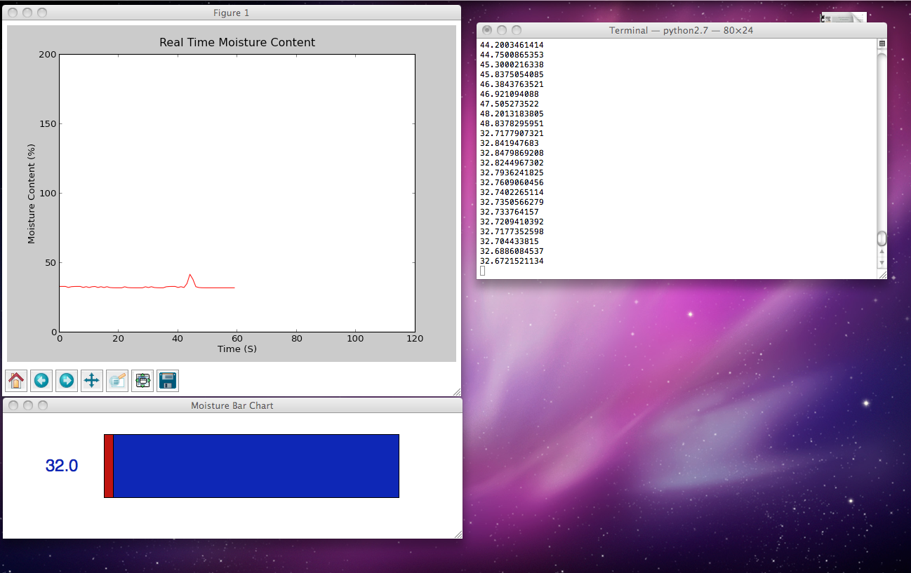
Once an argument is created through the serial port at the correct baud
rate, a graphic can be produced. For my final project I wanted to
integrate a live plotting graph as an output from moisture
inputs. To enable this it is necessary to package MatPlotLib into
Python to provide a mathmatical graphical interface. To create
the array I used a deque function and set the x and y axis, with a
small amount of values to decrease the dataset and set up the graph
arrangement.
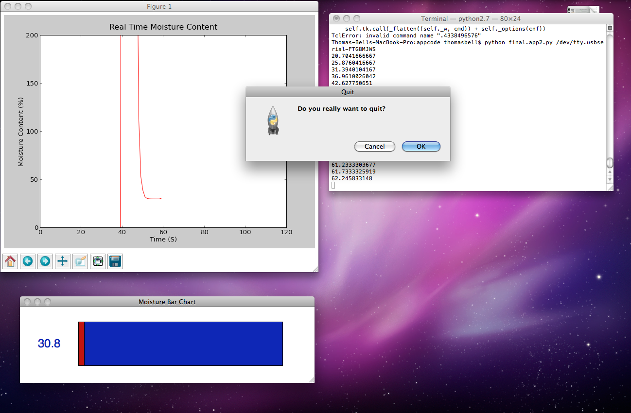
One of the main problems with the live data stream is that it was too
fast for the graph to update and needed to be slowed, using a count
sequence that slows the data feed by a significant factor so the graph
can update correctly. Additionally the code also required
to produce an output file that could be read an analysed with a
statistical package environment and a provide a reading for the
temperature once the moisture content is read, unfortunately I didn't get around to creating this output. The file can be
found here.
|
|
Final Comments:
The project, was an interesting undertaking as I had never having
undertaken any programming prior to this course and it provided a
stumbling block to the completion of the final product from the
outset. Further iterations will be needed if this were to be
developed into a comercial product, this process is more of a
conceptual starting point than a fully finalised product.
The spiral development technique that allowed the constituent parts to
be built seperately also increased the size of the product.
Through further development all parts could be pulled together to
provide a much smaller footprint for the circuit and the product
itself. Two elements of the product had to be clipped from the
production of the product due to my lack of knowledge and time, the RF
wireless component and a standalone power source any further
development should implement these processes as they will be
fundamental to the successful operation of the product in practice.
There are theortical shortcomings to the project as well, because the
natural electrical conductivity of timber varies from species to
species further calibrations are needed for the most common types of
timber species rather than the one that the product is presently set up
for. This should be incorporated in the application interface and
the python program as well as a time lapse option to increase the
reading of the sample.
Conclusions:
Overall I am
fairly disappointed with how the project turned out, I had to remove
elements of the product that I originally wanted to incorporate.
Barring this, I found the development of a entire project very helpful,
it helped gain an appreciation of how to break the project down into
small increments and gain a more holistic approach to electronic
product design.
|