Final Project
Week 0: Digital Fabrication Principles and
Practices
Week 1:
Collaborative Technical Development, Documentation and Project
Management
Week 2:
Computer Aided Design
Week 3:
Computer Controlled Cutting
Week 4:
Electronics Production
Week 5:
3D Scanning and Printing
Week 6:
Electronics Design
Week 7:
Moulding and Casting
Week 8:
Embedded Programming
Week 9:
Computer Controlled Machining
Week 10:
Input Devices
Week 11:
Composites
Week 12:
Interface and Application Programming
Week 13:
Output Devices
Week 14:
Networking and Communications
Week 15:
Mechanical Design and Machine Design
Week 16:
Applications and Implications
Week 17:
Invention, Intellectual Property and Income
Week 18:
Project Development
Week 19:
Final Project Presentation
|
Composites
This
week we had to construct a workflow for developing composite
casting. Due to the fact that we are a new lab with no local
guru, me and Roy decided to team up to create the workflow, as we
thought that we could help each other out to develop the scheme of
work. This meant, acquiring the parts for all the composites and
creating the moulds and developing the workflows through trial and
error.
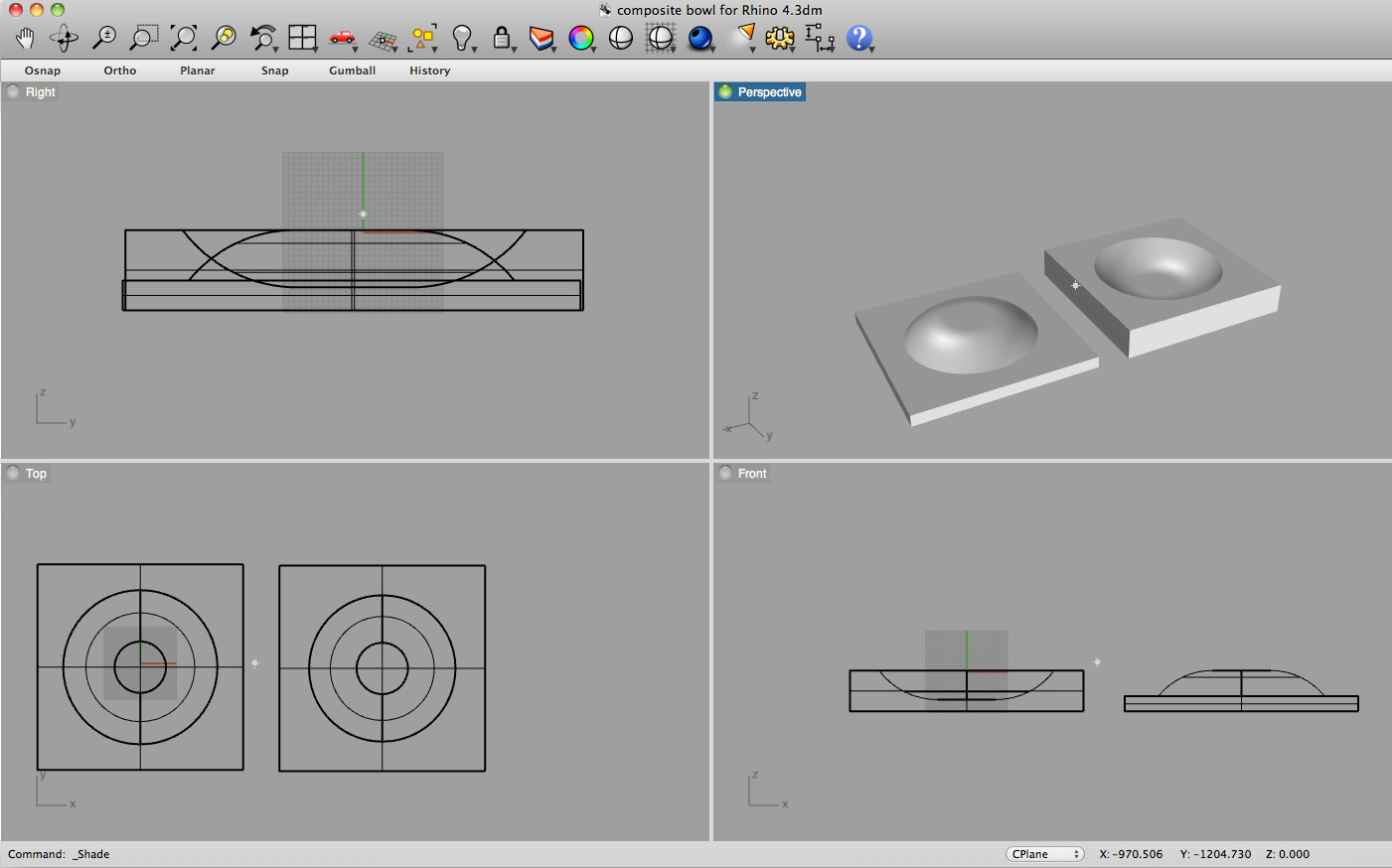
Design:
To enable a more simplistic workflow, the design was to be a
large 6mm thick bowl constructed within Rhino/Solidworks, with us both experimenting
with different composite materials and trying to define the necessary
workflows.
Once the design was finalised, the file was exported and open in the
same program (Cut3D) as was used in the moulding and casting week of
the Fab Academy. We defined all the tools paths for both the
negative and positive parts of the mould seperately and exported them
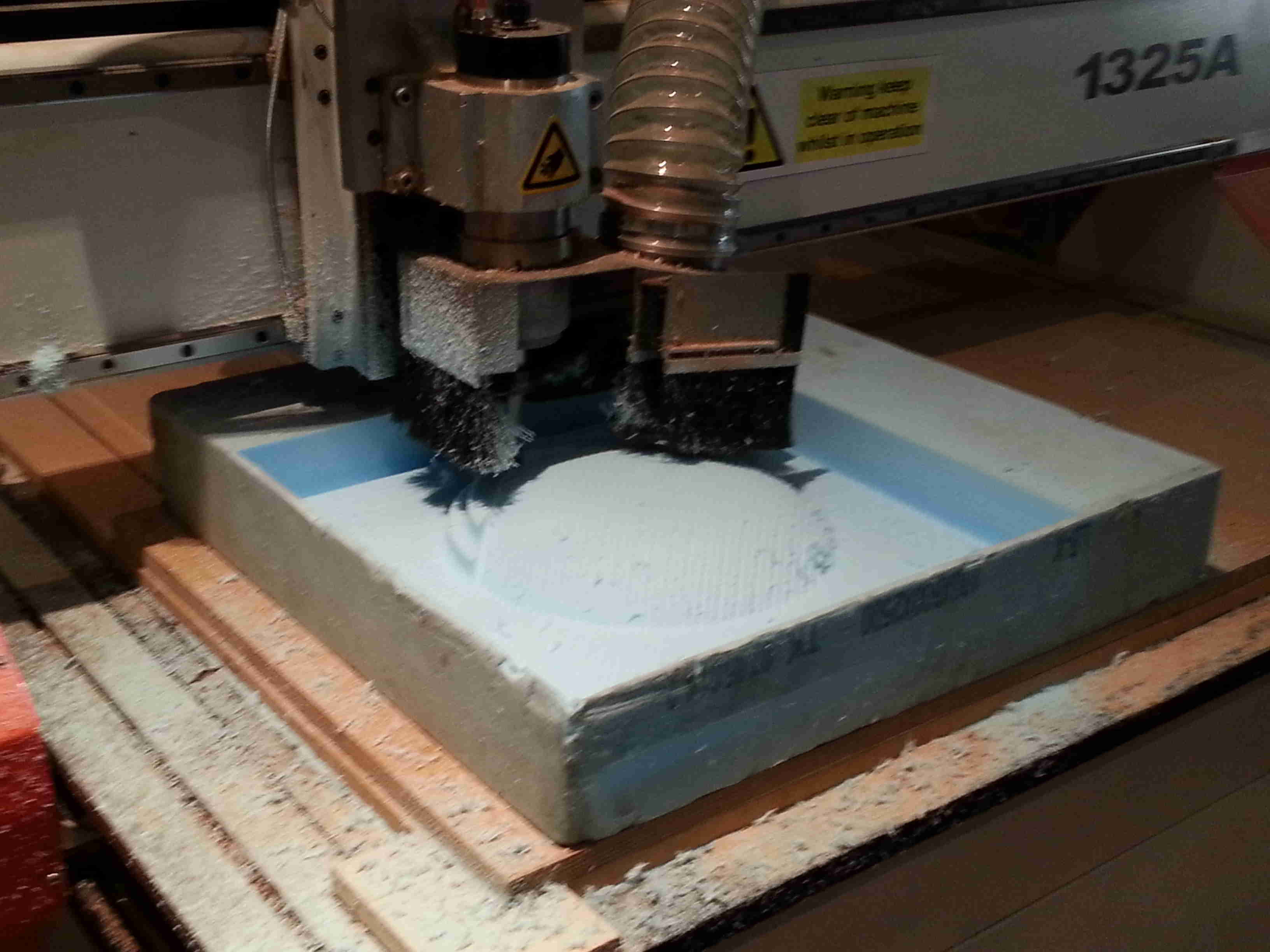
as a millimetre GCode for use on the large milling machine. It was decided to
use some modelling foam to construct the mould parts, and this was
milled out accordingly.
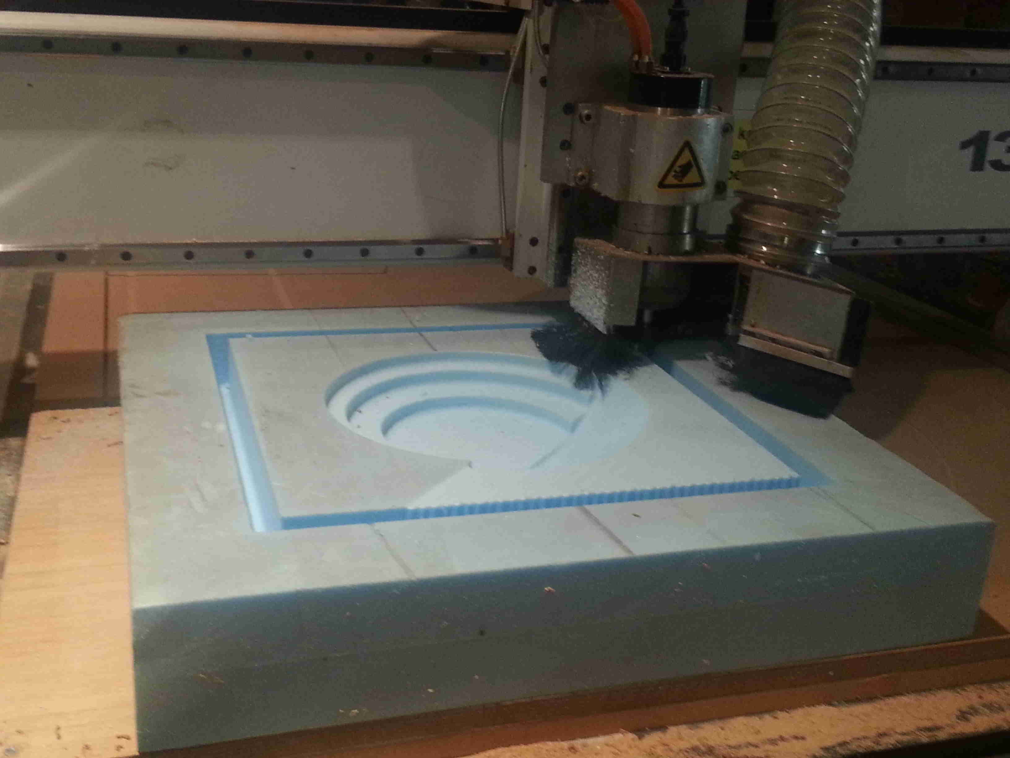
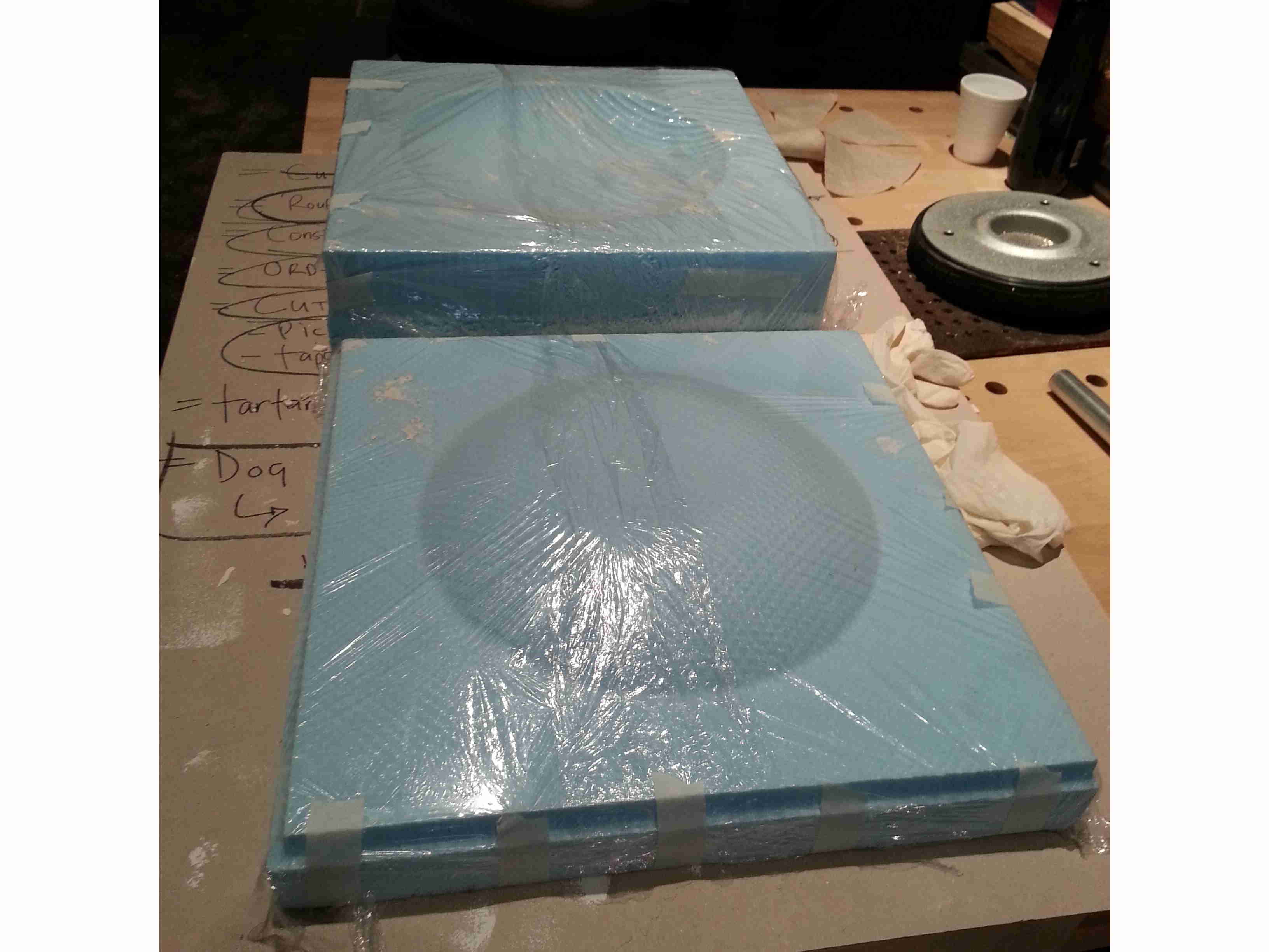
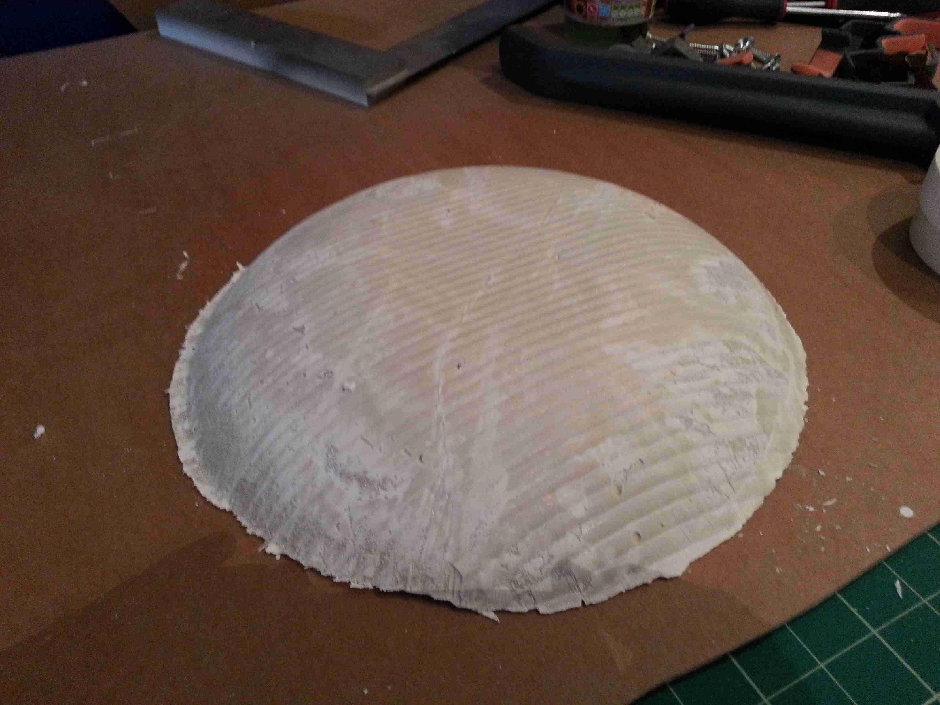
Milling:
It was noticed that during the milling process the first piece (the
negative) that was milled the finishing pass was only directed in one
angle, so there was a ripple effect on the mould. It was thought
that this texture would be quite a nice contrast to the inside face if
whilst milling the positive mould we made sure that we ran an
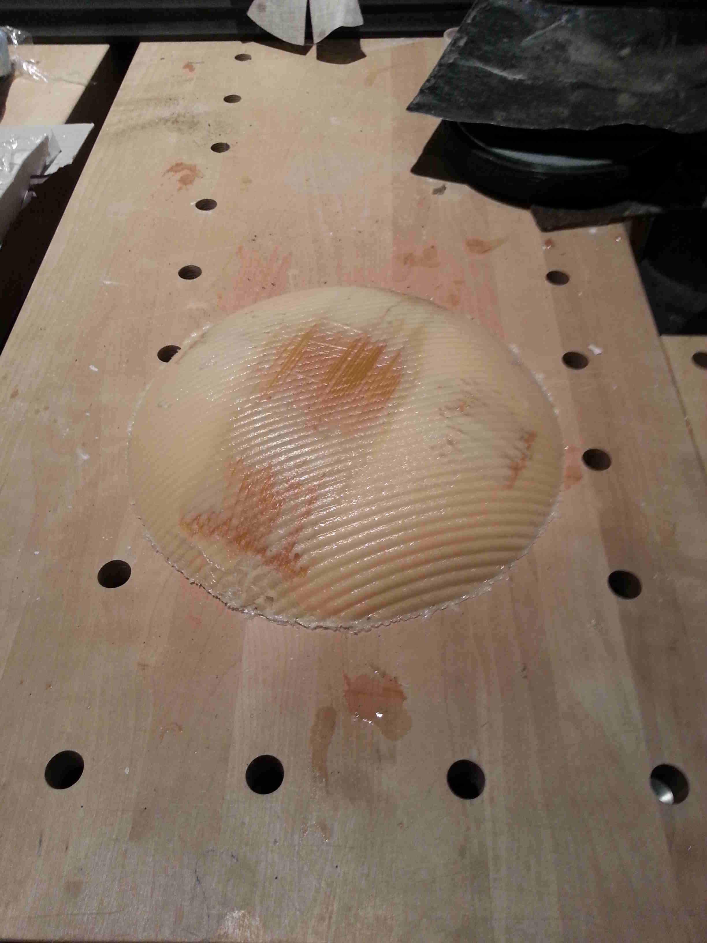
additional pass at 45 degrees to the initial pass. Conducting
this second pass didn't create a completely smooth texture because the
mill piece was fairly large and the stepover we set for the GCode was
slightly too large to ensure a smooth finish, in contrast it created a
surface with many little nodules that gave an interesting juxtaposition
to the underside of the bowl.
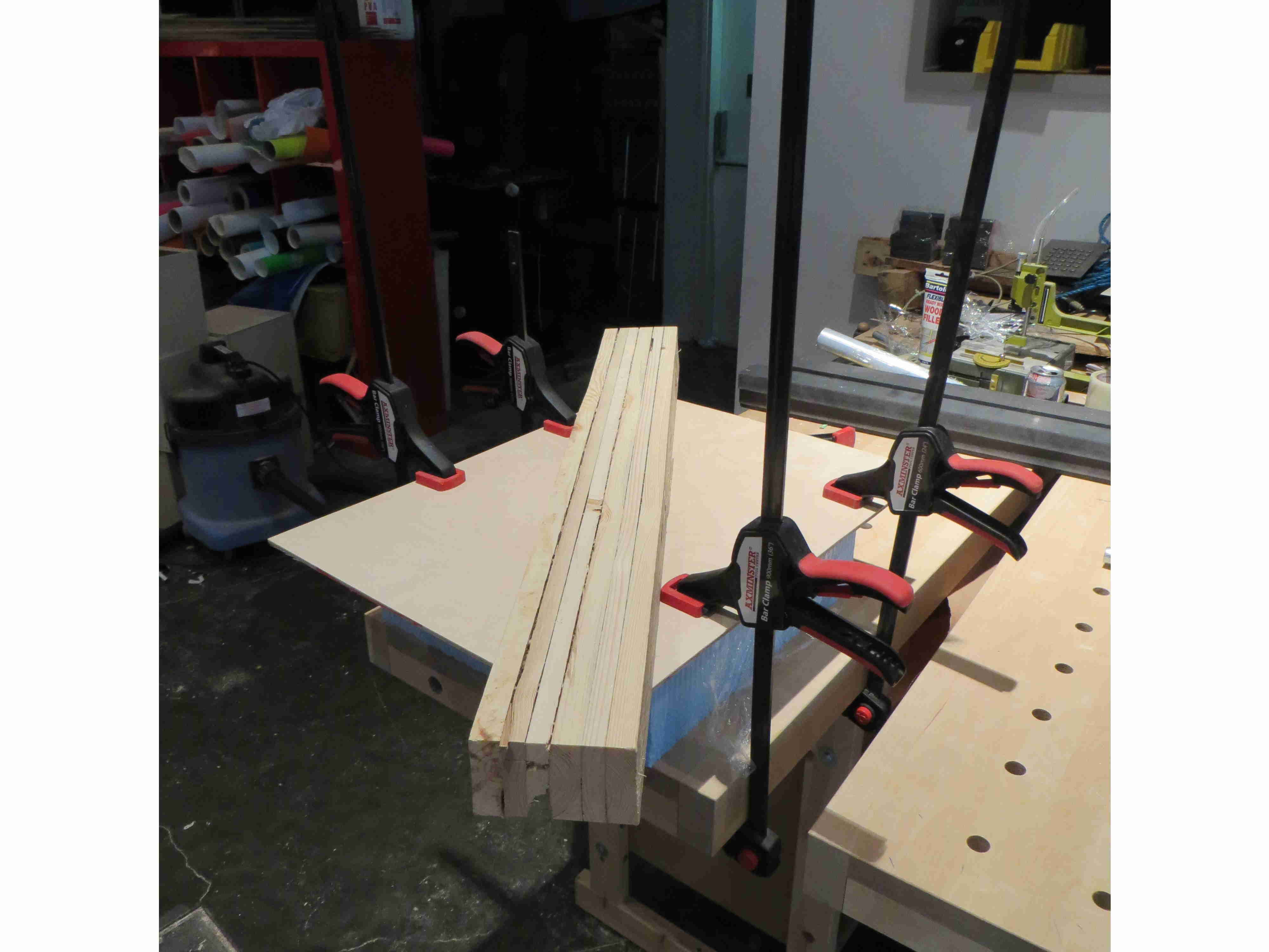
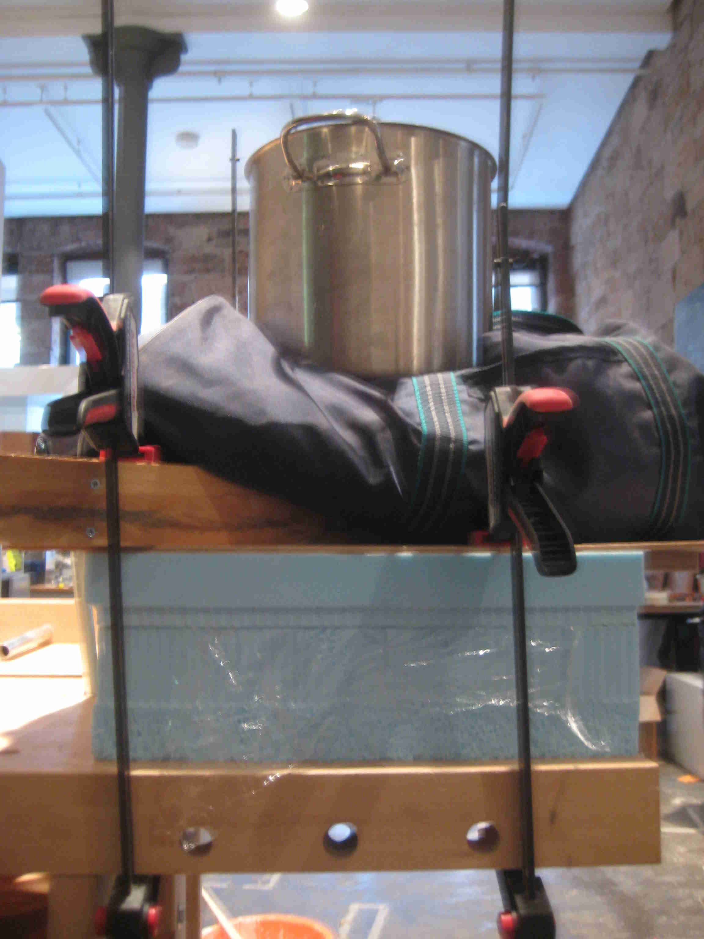
Casting:
At the lab we didn't have access
to the vacuum bagging techinque so the methodology of casting was to
clamp and weight the mould to create the necessary pressure to bond and
bind the laminations together. During the creation of the mould
we ensure that there was a significant border around the bowl to allow
us extra room to clamp the moulds and place the weight required.
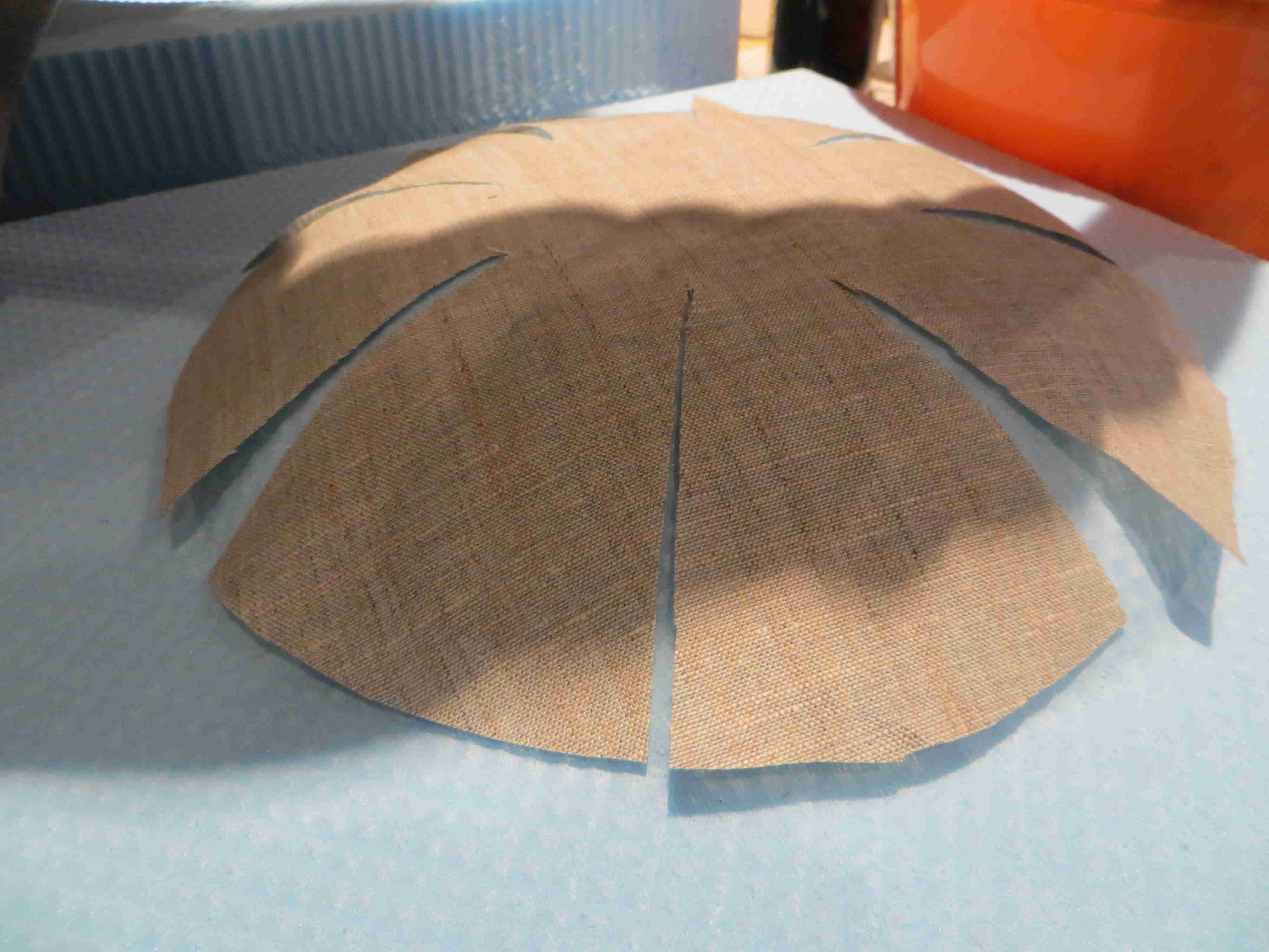
We first attempted using linen and Herculite composite, because the
bowl has a curve profile the template for the linen had to allow for
variation of the profile and not allow the linen to crease. Therefore,
star shaped layers of linen were laser cut to accomodate the profile of the
bowl.
|
|
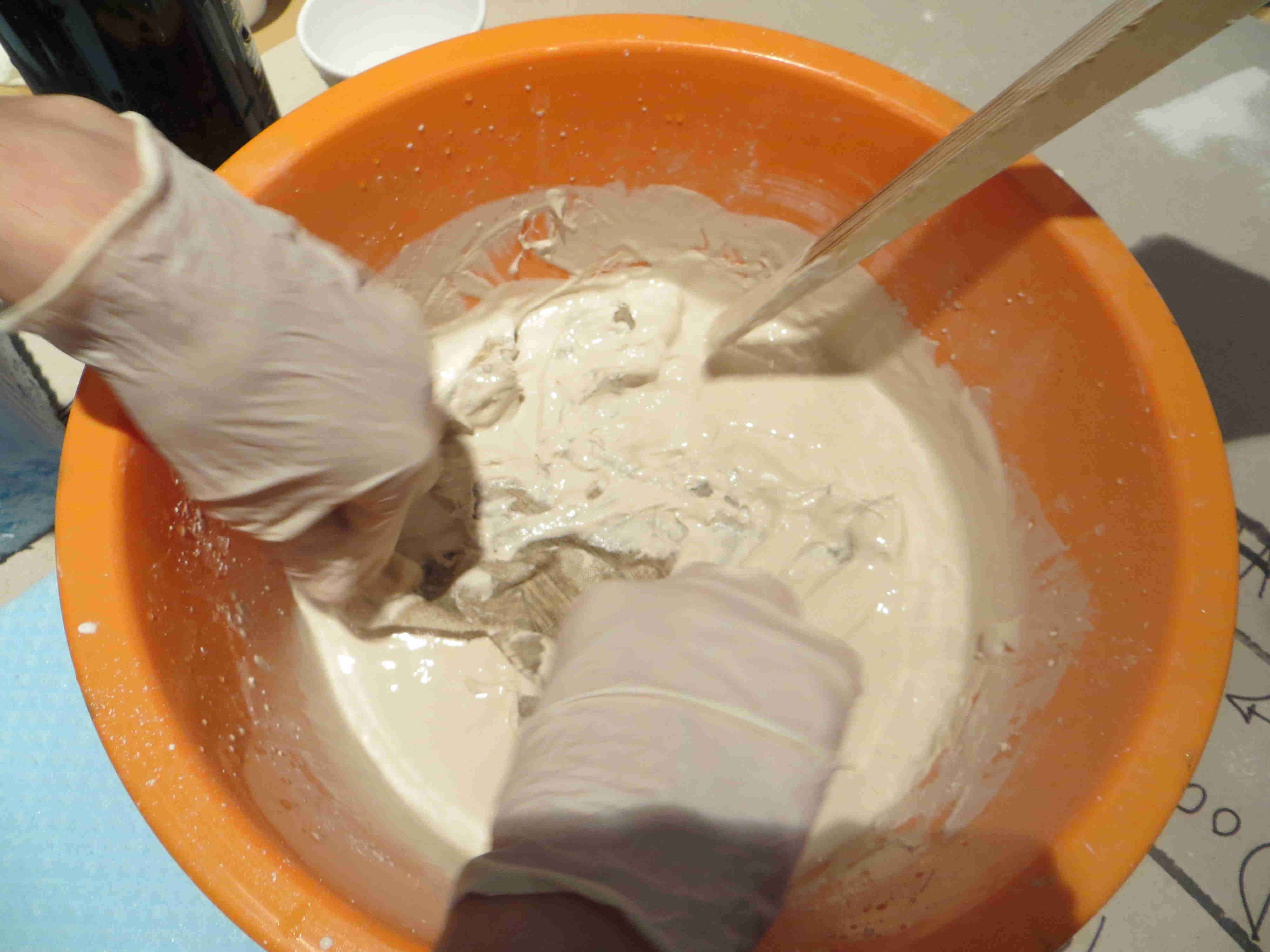
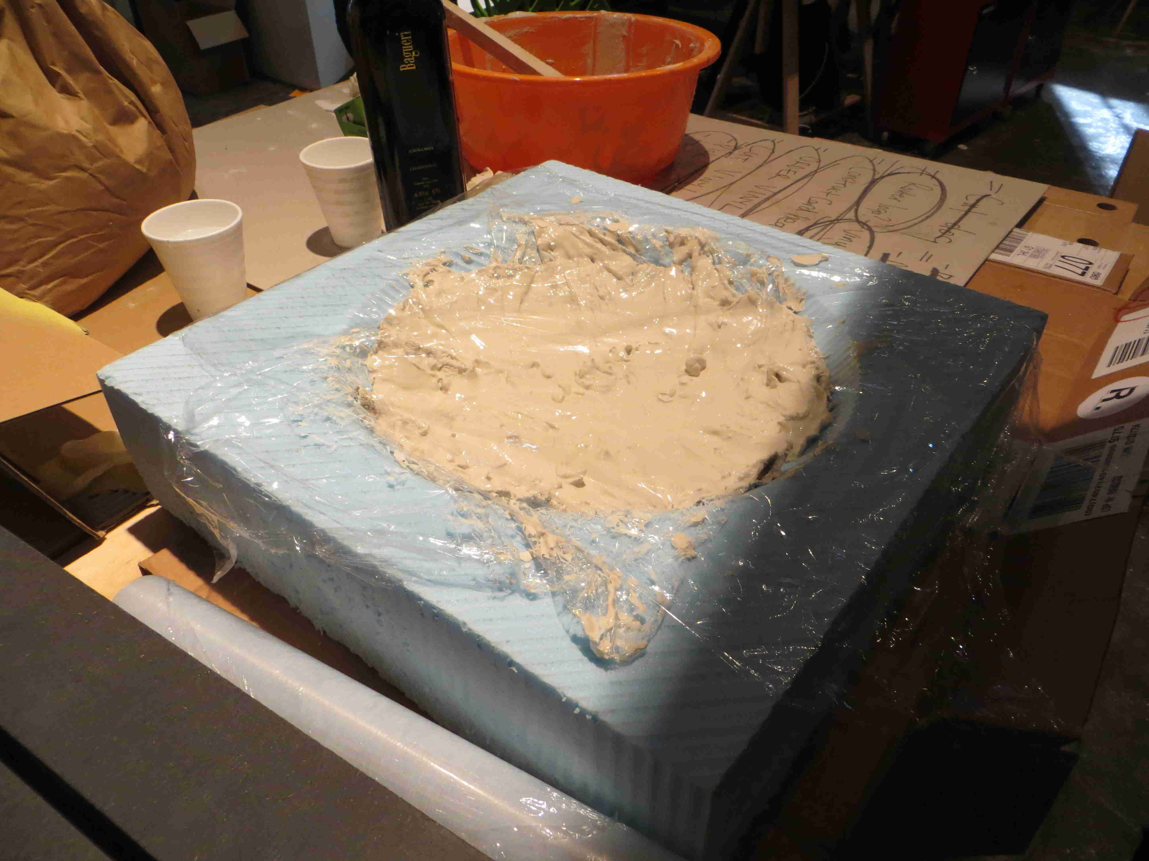
Firstly, we used a layer of clingfilm to line the negative part of the
mould prior to mixing to ensure a easy release from the mould. The
Herculite was then mixed in accordance with the recommendations given
by the manufacturer once the mix was ready we dipped two layers of
linen into the Herculite and placed them in the mould and poured in
the remainder of the Herculite. Once the linen was saturated with
the Herculite it was very difficult to flatten and orientate into the
necessary position in the mould.
|
|
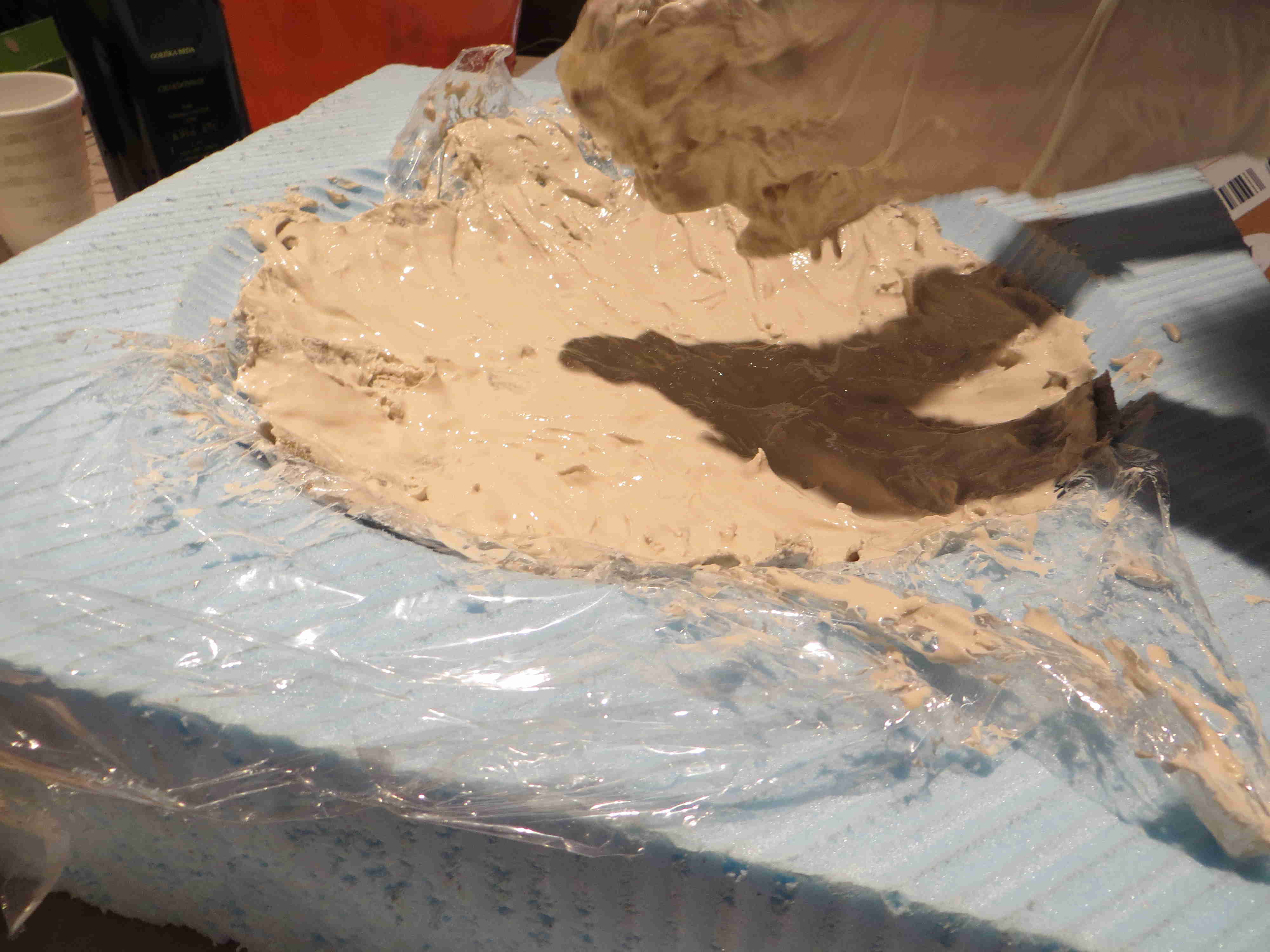
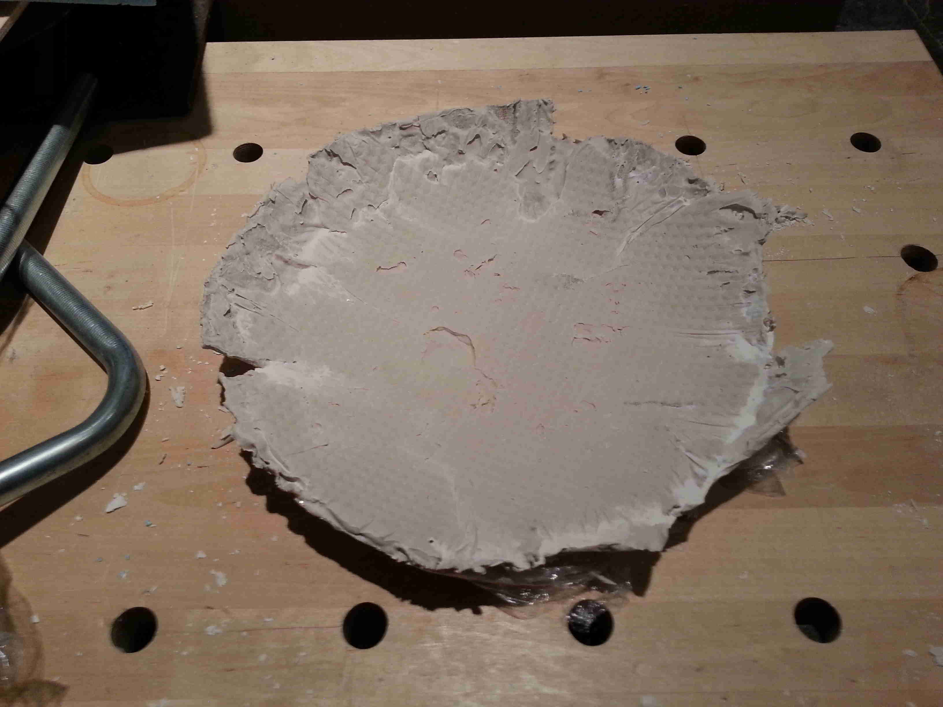
The first cast, didn't turn out as intented; the cling film was just
laid in the mould and was not fixed properly down to the negative and
postive mould. This allowed the cling film to fold up
into to material although it did allow for an easily release of the
finished product - it was noted when the composite material was
splashed onto the bare foam it was difficult to remove so a release
mechanism should always be used. Additionally, we found out that
we did not put
enough of the casting material to fill the mould entirely so the
pressure we placed upon the mould still caused air pockets to form and
a non complete cohesion between all the laminations.
|
 |
For
the second attempt, we ensured that the cling film was sufficient
anchored using masking type and ensured that the cling film could
stretch to form a tight alignment with the mould. Secondly, the
amount of material we used was increased to ensure that the mould was
sufficiently filled. The methodology this time was to pour a base
layer of Hermculite before setting the dry linen on top and then pouring
a second coat of Herculite on top and then applied the pressure with
clamps and weights as before.
|
|
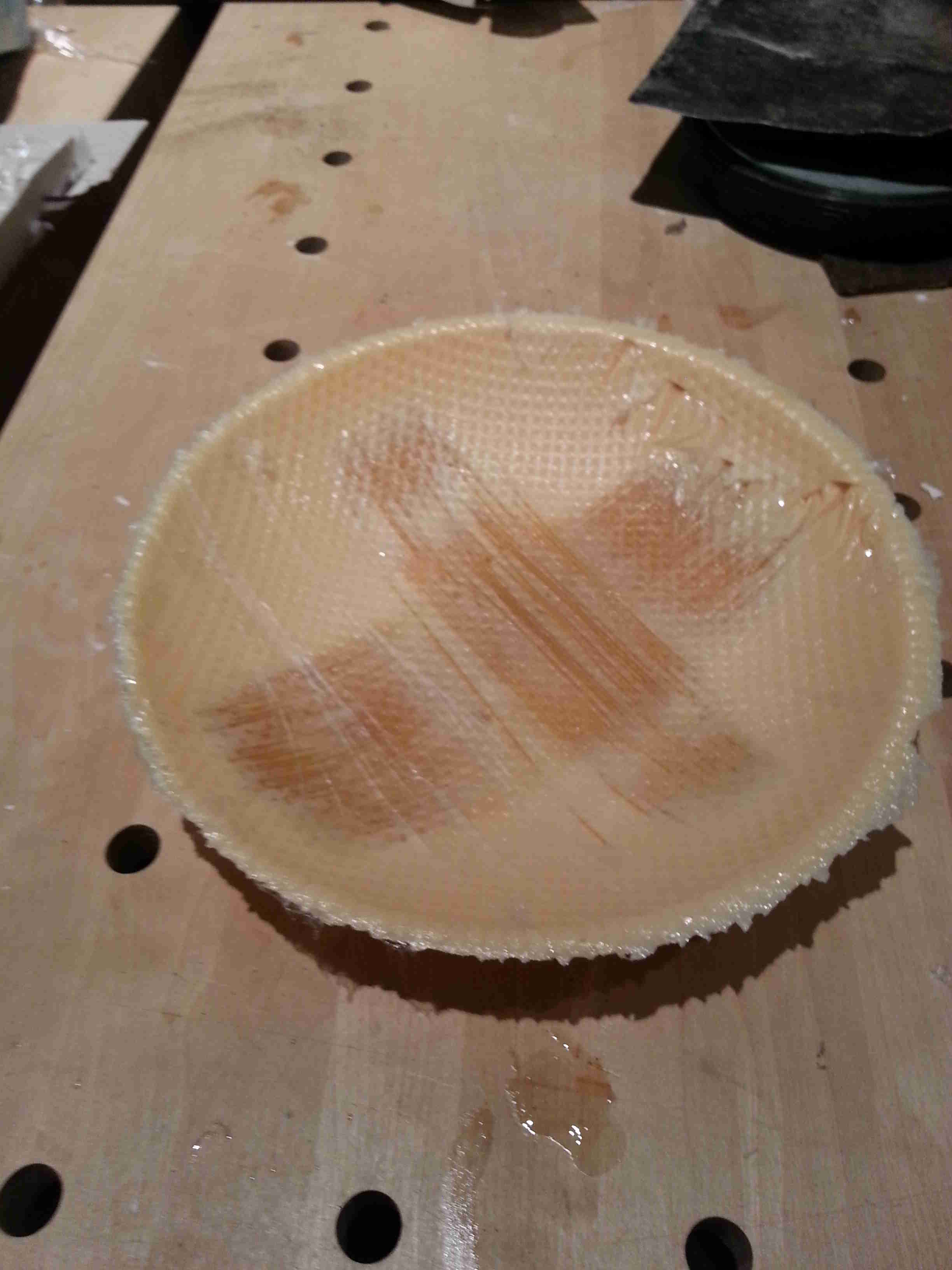
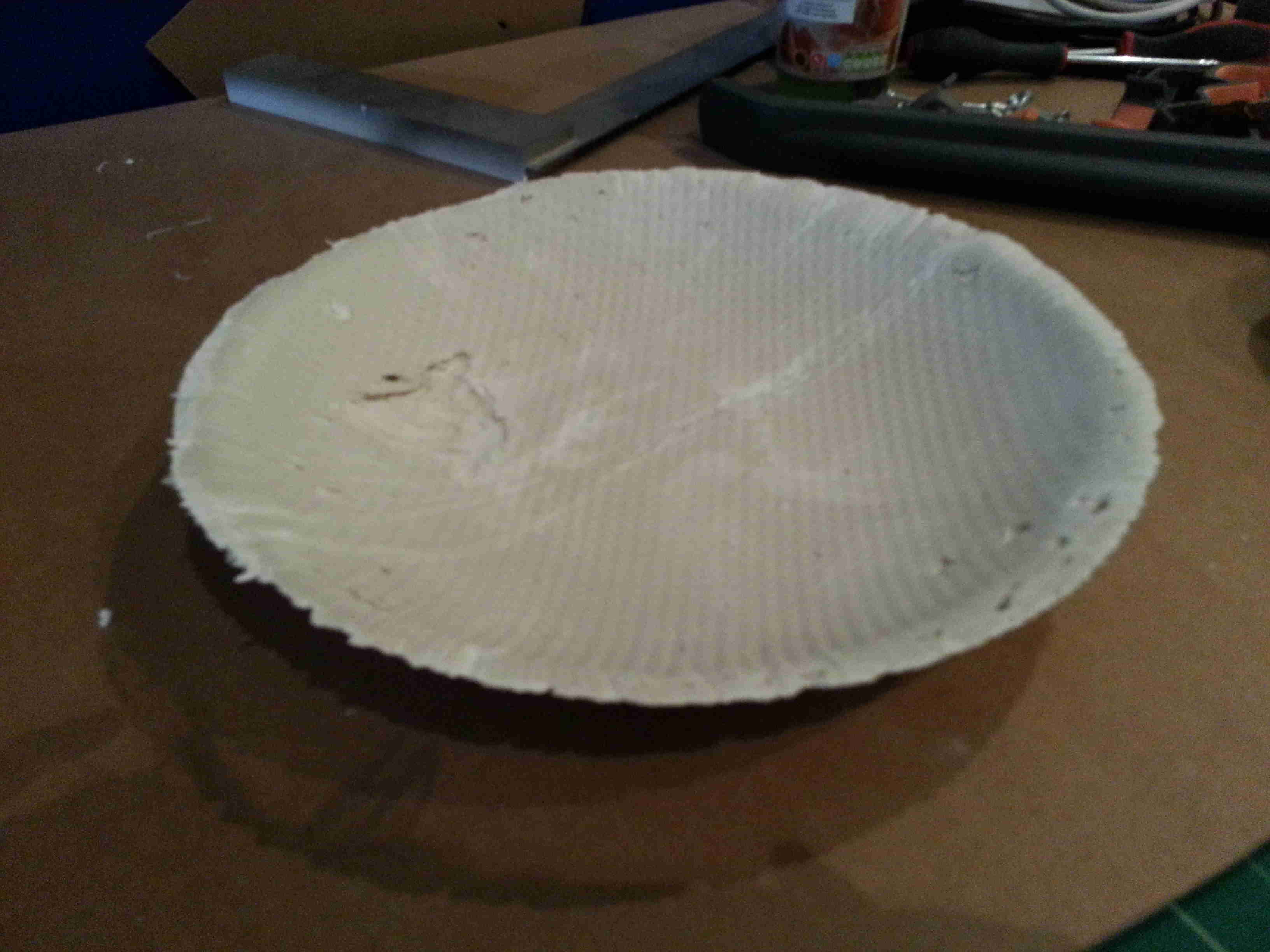
The outcome was significantly better than the previous attempt,
although the amount of mix was still slightly short - next time the
volume of the bowl wil be measured and the amount necessary will be
determined. It become slightly more difficult to find the exact
amount necessary as linen/fibre is being added, the volume of which
will also have to be determinded to achieve the perfect amount.
The final below picked up the contours of the mould very well but there
was areas where there was cling film trapped in the cast and where the
pressure within the mould did not allow for an even covering of the
matric to permeate through all parts, so there were areas where the
linen was visible. The linen which was visible was very strong
and showed that when the two materials are bonded they do form a strong
and stiff material.
|
|
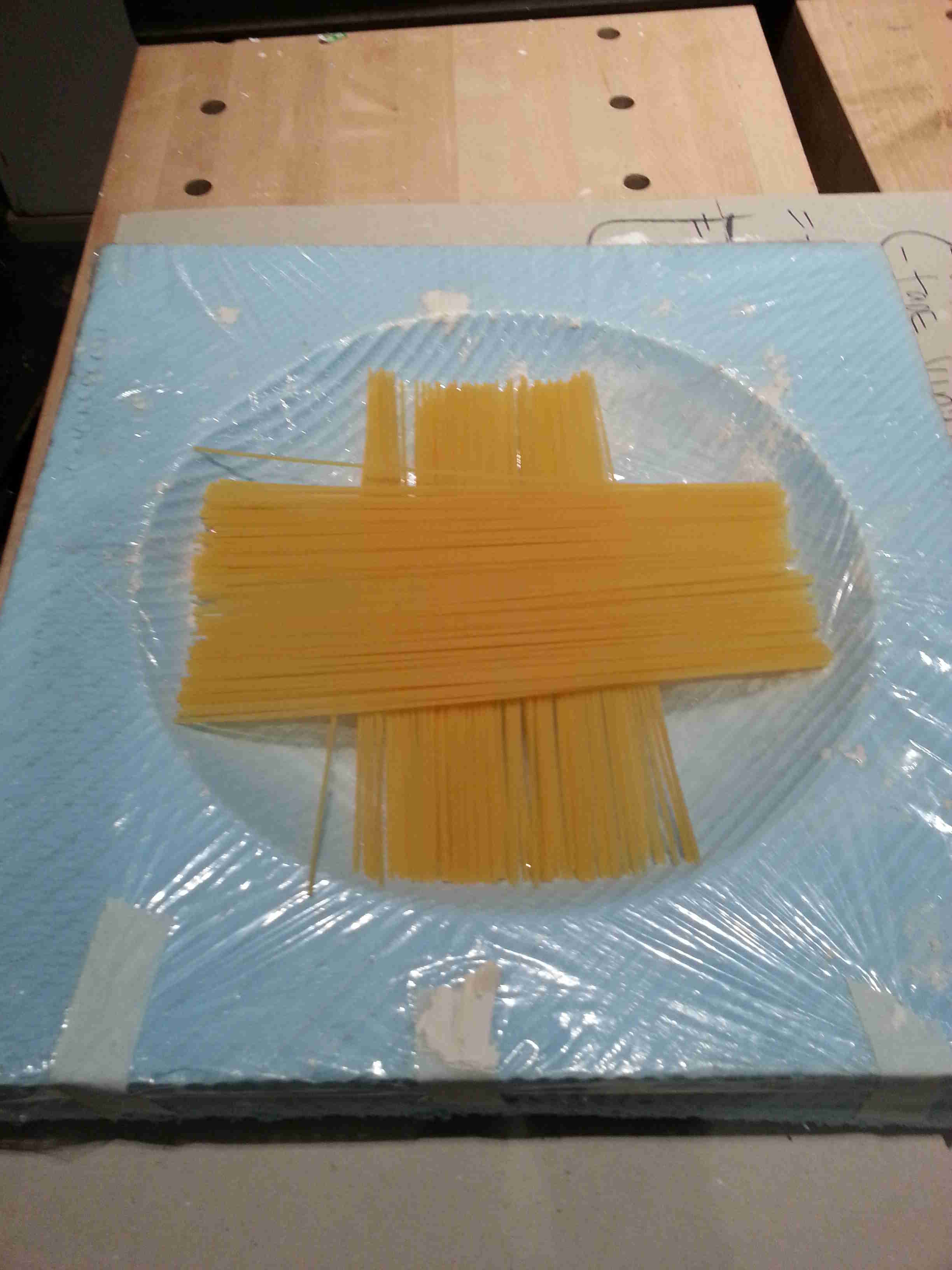
For the second methodology the idea was to use Polyurethane as the matrix and
spaghetti as the matrix for the material. It was thought that
aligning the spaghetti and ensure that they were held firmly in place
along the curved elements of the bowl would prove tricky. The
idea was to place the spaghetti first and then pour the Polyurethane on top
of spaghetti to allow for a strong bond to develop and allowing the Ployurethane to be orientated and secured in the right locations.
 |
Afterwards, we mixed the two parts to form the Polyurethane,
the mixture was still fairly liquid so we began the preparation of the
casts but before we realised it the mixture started to cure rapidly and
we lost the first batch of the casting material. The 2nd attempt
we prepare the cast properly prior to mixing, because of the problem we
had with the final plaster cast, extra material was used. This
was a mistake, because the Polyurethane
maintained liquid state for approximately 5 minutes after mixing,
therefore there was a large amount of overflow when pressure was
applied onto the mould causing quite a mess.
The cast was successful, but there were elements of cling film that we
used fo the release mechanism embedded in the material. Next time
this procedure is used. it is recommended not to use the cling film as
a real mechanism as the chemical reaction was extremely exothermic and
caused the cling film to deform into the cast. Once the edges
were sanded the bowl looked good, but you could add an additional
colour pigment to the Polyurethane
to make the bowl more attractive. Overall, I was fairly pleased
with the result, given a through more attempts the workflow could be
quick and efficient but we finished there because we didn't want to use
all the material as other academy students will need it.
|