Final Project
Week 0: Digital Fabrication Principles and
Practices
Week 1:
Collaborative Technical Development, Documentation and Project
Management
Week 2:
Computer Aided Design
Week 3:
Computer Controlled Cutting
Week 4:
Electronics Production
Week 5:
3D Scanning and Printing
Week 6:
Electronics Design
Week 7:
Moulding and Casting
Week 8:
Embedded Programming
Week 9:
Computer Controlled Machining
Week 10:
Input Devices
Week 11:
Composites
Week 12:
Interface and Application Programming
Week 13:
Output Devices
Week 14:
Networking and Communications
Week 15:
Mechanical Design and Machine Design
Week 16:
Applications and Implications
Week 17:
Invention, Intellectual Property and Income
Week 18:
Project Development
Week 19:
Final Project Presentation
|
Computer Controlled Machining
This
week's assignment was to design, fabricate and construct a large
product using a large scale computer controlled cutter (like a
Shopbot). As long as the product could be designed from the 6mm
thick piece of plywood board with dimensions of 2440 x
1220mm. Due to the fact that the plywood being used was only 6mm
I didn't want (or trust) it to provide the necessary strength and
stiffness characteristic for a fully weight bearing piece of
furniture. I decided to design a piece of furniture that could be
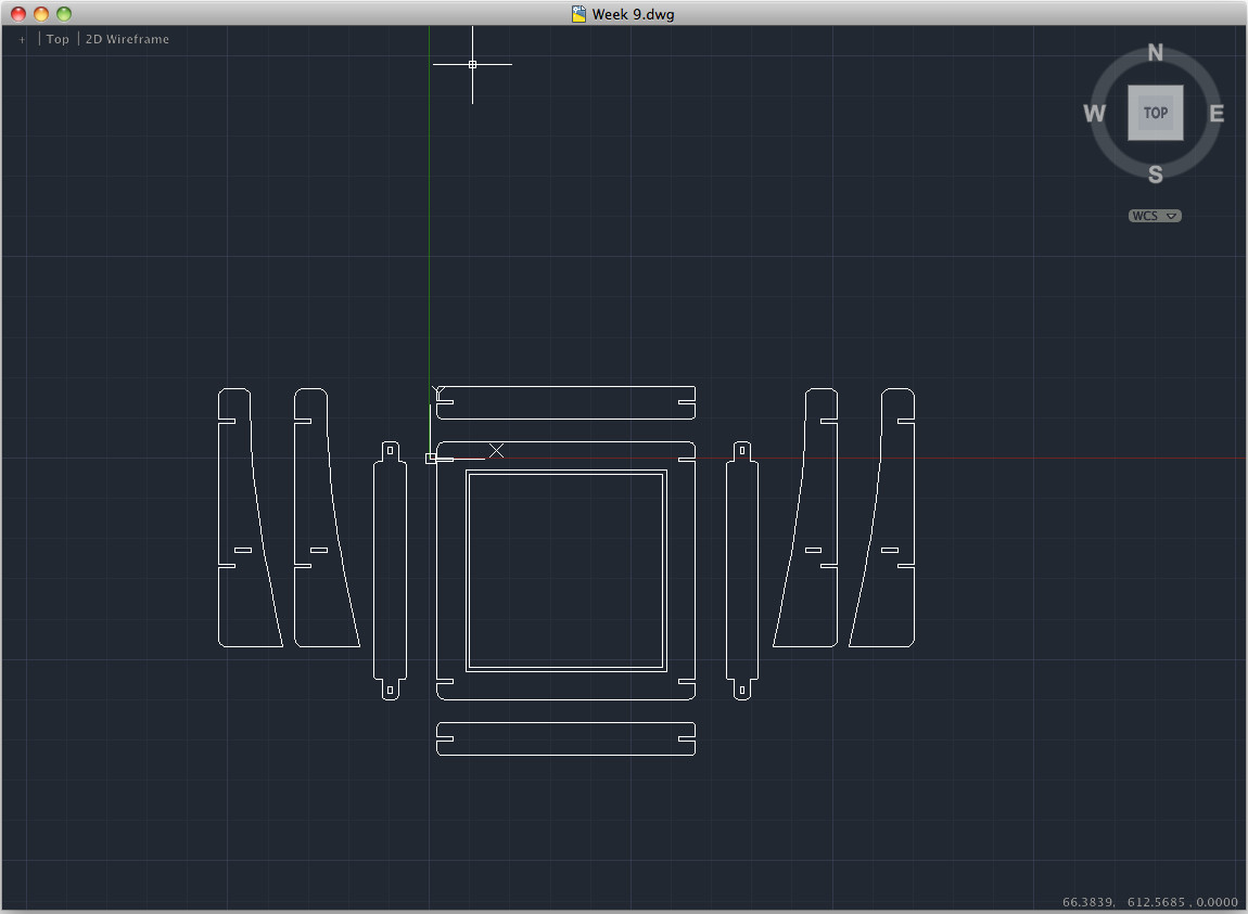
either a foot stool or a small table for placing drinks. Using
the snap construction techniques used in Week 3, I designed the piece
in 2D using a Cad Package and exported the file as a vector package
(.dxf).
Setting and adjusting tool paths:
I
imported the .dxf in to VCarve to allow me to create the tool paths for
the computer controller cutter. Within the program I used the
'nesting' tool within the program to arrange my shapes into the
smallest possible area size for cutting efficiency. Once I began
creating toolpaths for the shapes, I had to make should that the
correct order of cutting was adhered to for efficient and safe cutting
to be conducted. This was by ensuring that the any cuts within
the centre of a shape was carried out initially and the final cut of
each shape was the outline of the shape. By selecting the profile
cut, you can select the depth of cut, which can give you nice routed
elements or cut through the material completely, in this instance I
selected 6.5mm depth cut to ensure that the cutter went through the
material. Once all the necessary toolpaths were set up, they need
to be exported to the necessary file format.
Using the CNC Router:
The
6mm Plywood, was placed centrally on a sacrifical base of timber
preinstalled in the bed of the router and then the plywood sheet was
fixed at regular locations with wood screws along the edge of the
board. The axes of the cutting piece were zeroed at the relevant
locations, all extractors and cooling equipment was turned on a cutting
commenced! The process was fairly quick and the overall finish
was fairly good, unfortunately due to the cupping in the sheet
(although we had orientated the sheet the right way to the distortion
when placing it in the machine) was too great and the tolerance (0.5mm)
I had given to the depth of cut was too small to cut through the
material fully. Where this had occurred, I just finished the cut
with a sharp knife and sanded the edges down accordingly to avoid
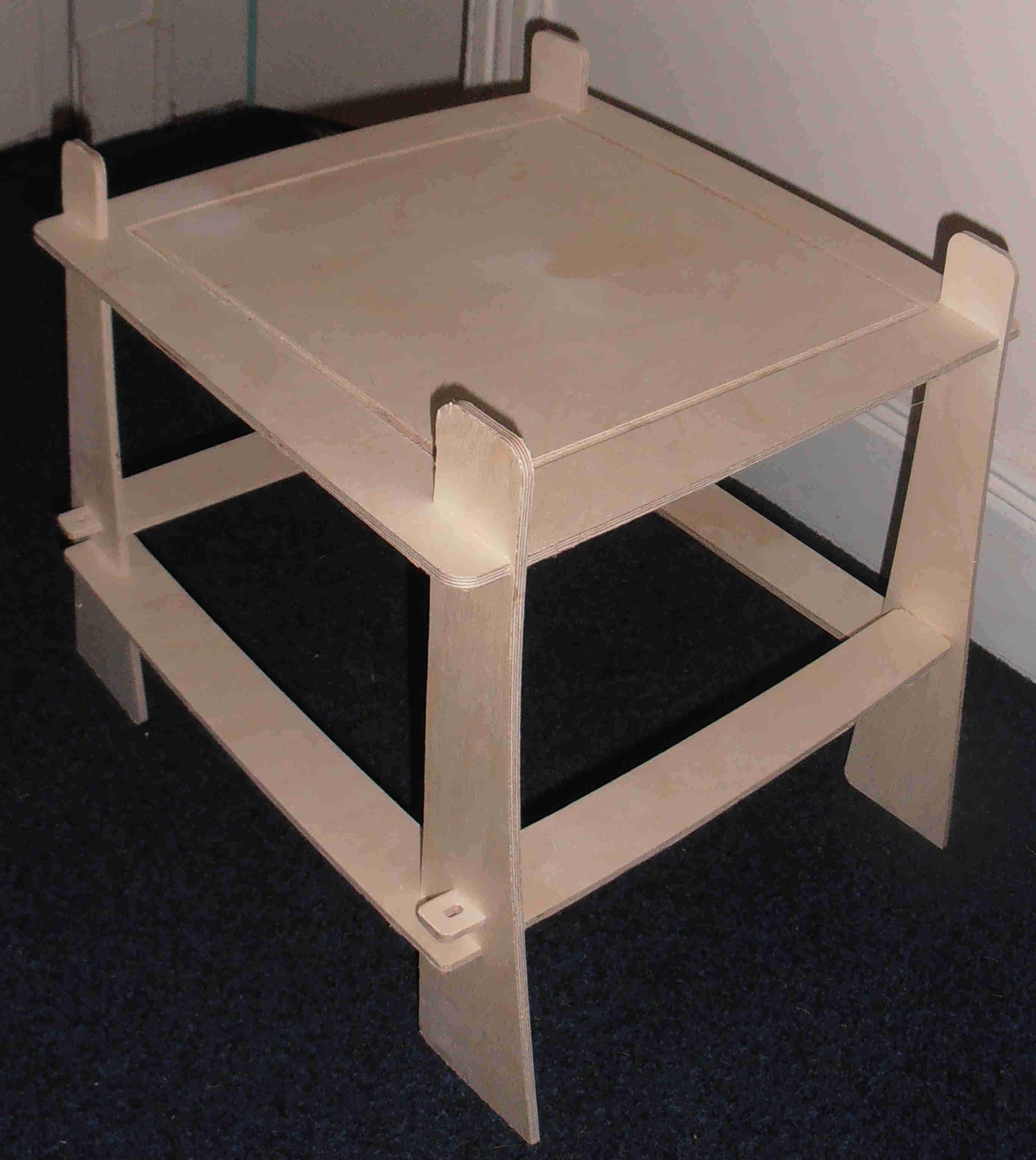
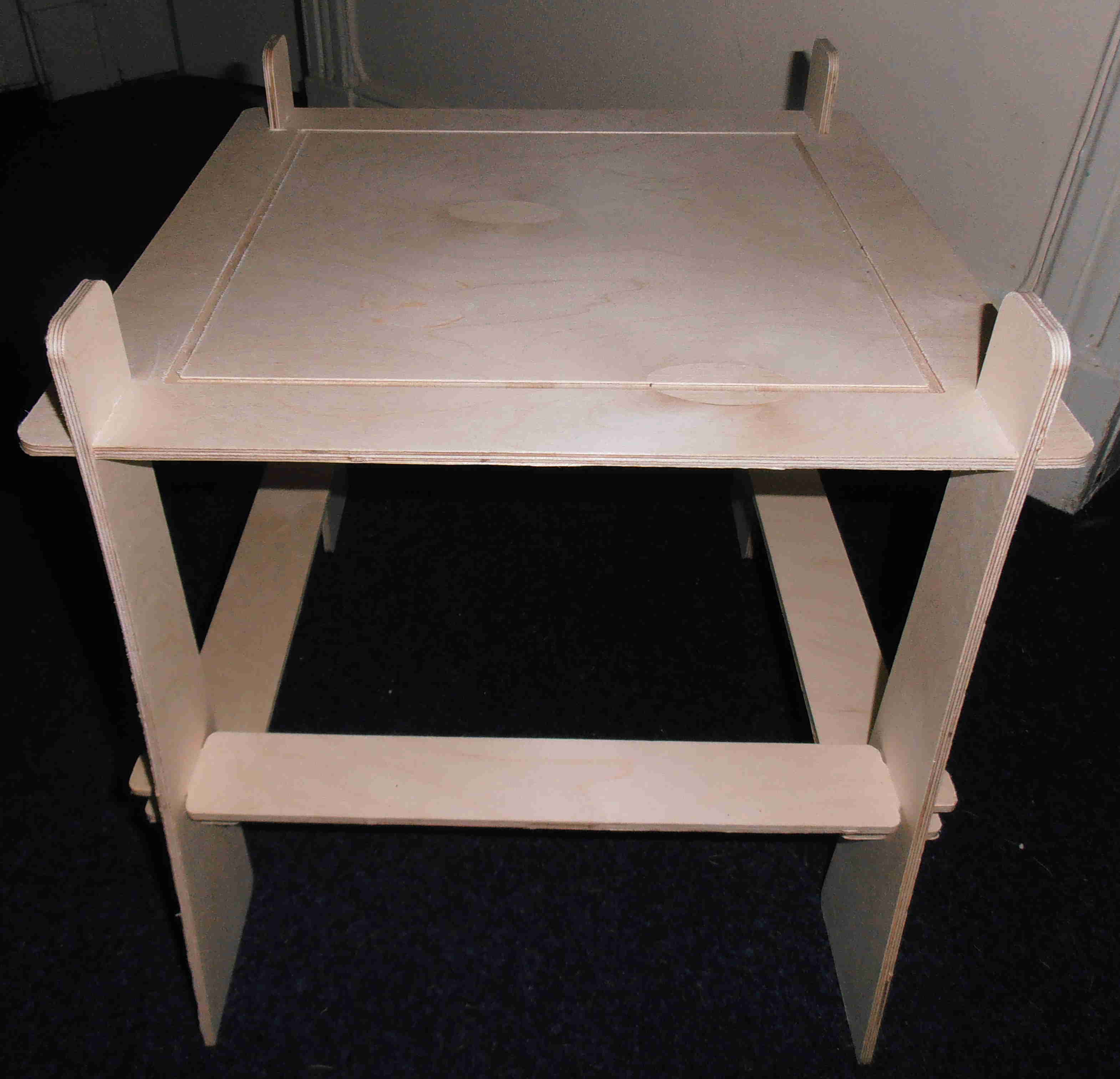
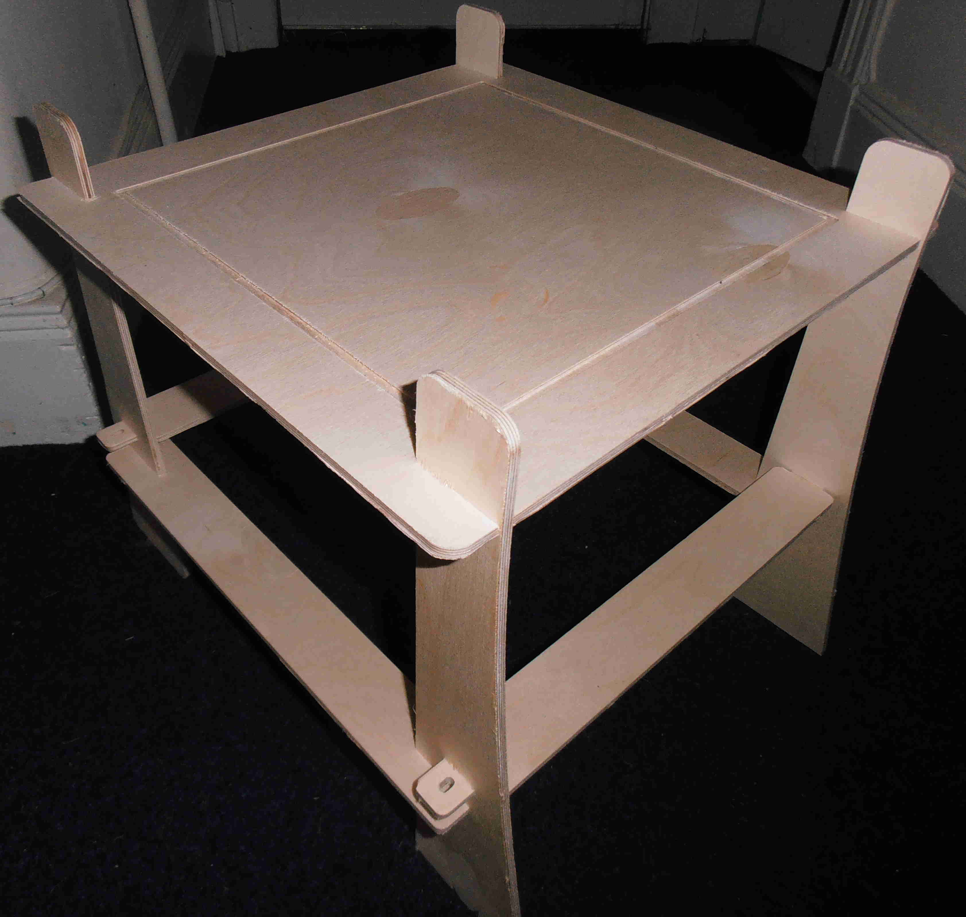
splintering etc. Once the pieces were post processed all the
pieces of the small table/foot stall fitted together neatly (with a
little bit of gentle persuasion). I believe with the inclusion of
mechanical fasteners could be an invaluable tool for creating fast
scaled prototypes from wood or other similar materials. Overall I
found the process, very quick and neat and would be a process I would
consider implementing next instead of purchasing some flat packed
furniture.
|