Final Project
Week 0: Digital Fabrication Principles and
Practices
Week 1:
Collaborative Technical Development, Documentation and Project
Management
Week 2:
Computer Aided Design
Week 3:
Computer Controlled Cutting
Week 4:
Electronics Production
Week 5:
3D Scanning and Printing
Week 6:
Electronics Design
Week 7:
Moulding and Casting
Week 8:
Embedded Programming
Week 9:
Computer Controlled Machining
Week 10:
Input Devices
Week 11:
Composites
Week 12:
Interface and Application Programming
Week 13:
Output Devices
Week 14:
Networking and Communications
Week 15:
Mechanical Design and Machine Design
Week 16:
Applications and Implications
Week 17:
Invention, Intellectual Property and Income
Week 18:
Project Development
Week 19:
Final Project Presentation
|
Input Devices
The
requirement for this topic was to construct a mircocontroller board
with a sensor and demostrate that the sensor is working through a
graphical interface on a computer. There are several example
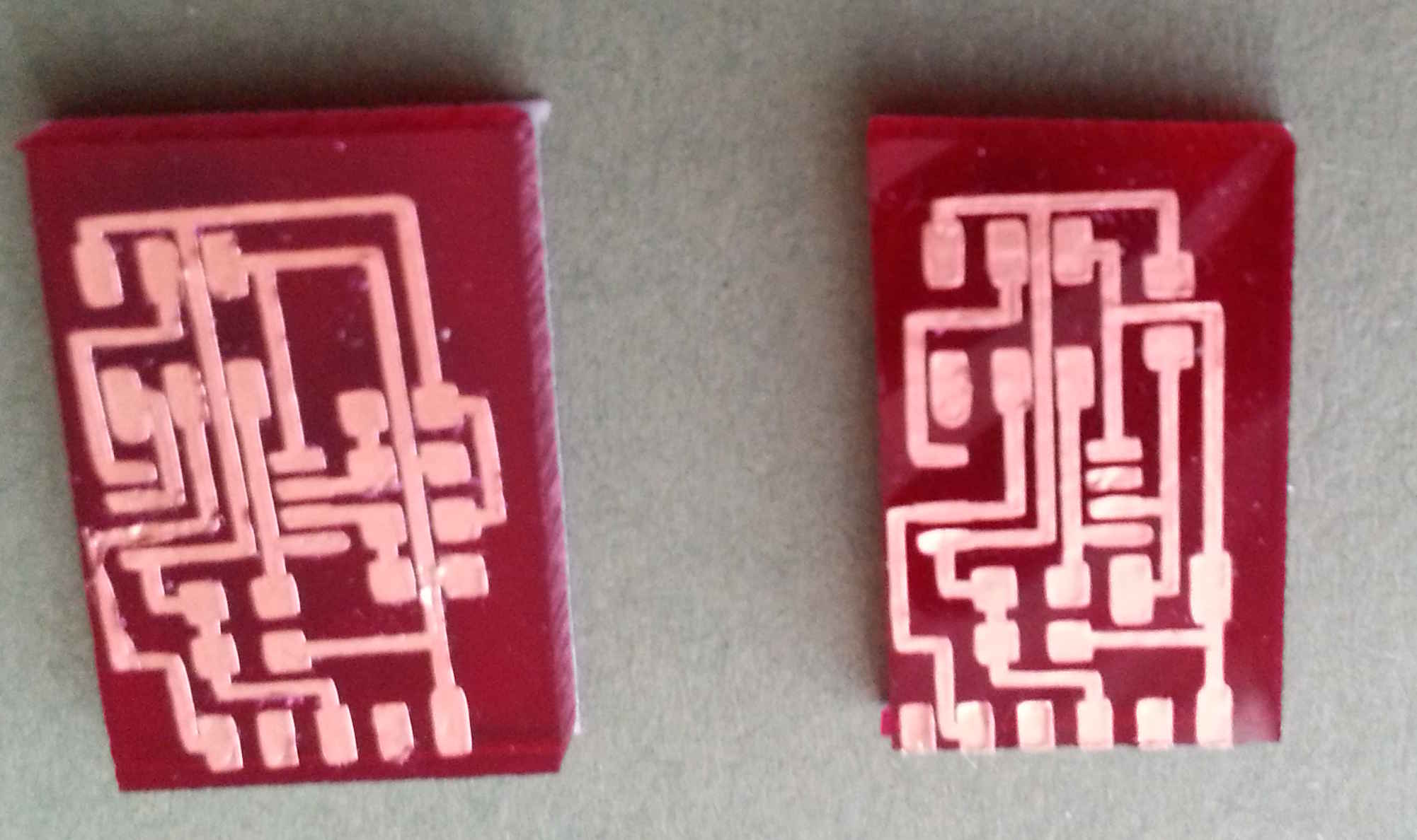
boards on the links within the lecture notes - I decided to construct
two of the example boards temperature and light
(using the phototransistor). Unfortunately, this week I was
unable to use the Modela to mill the boards so I decided to vinyl cut
the boards instead. I thought this was a good opportunity to use
the vinyl printer as the circuit boards consisted of a small amount of
components and would leave less opportunity for error.
Using the Fab Modules:
For this I had
to set up my computer using the Fab Modules - because I was using a Mac
OS I had to additionally locate the printer within the Fab_send
file. This was acheived by installing the necessary drivers using
C.U.P.S,
to access CUPS you have to type localhost:631 into your browser and you
can add the printer following the links (N.B. the printer needs to be
plugged into your computer to recognise the printer). Once this
is achieved, you have to enter the fab_send (directory:
usr/local/bin/fab_send) file and alter the .camm file output to
'printer=Roland_GX-24; lpr -P$printer "$file"' to make the fab module
send to the correct printer. Once this was done, the fab modules
printed the circuits quickly and fairly effortlessly! I then
placed the copper traces onto a piece of acrylic and weeded them
accordingly, because the vinyl printing was so quick I made several
circits just in case I damaged any of the circuits whilst constructing
and stuffing the board.
|
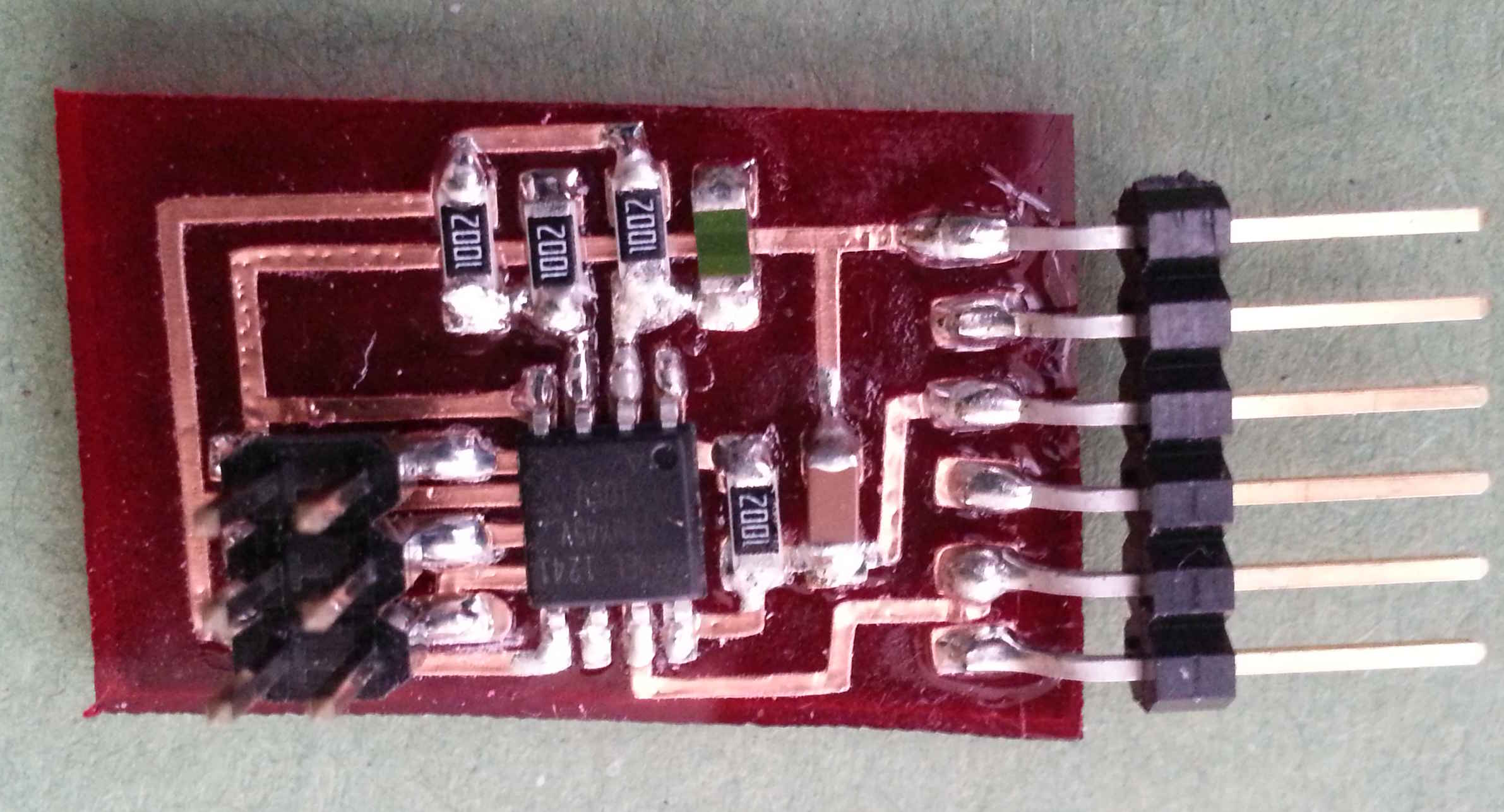
Whilst, I was
soldering the board the glue on the traces tended to lift as the glue
melted when the temperature of the soldering iron surpassed the melting
point of the glue. Luckily, the copper traces are very malleable
and were able to be stuck down again without breaking, if they were
treated carefully. Once all the components were placed on the
circuits, I used additional superglue on the board to stick down any of
the components that could be placed under any force or pressure, such
as the FTDI Headers.
Programming and using python:
Following the tutorial
from Providence, I downloaded PySerial link on the tutorial and
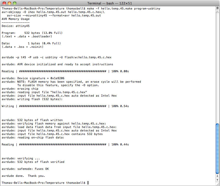
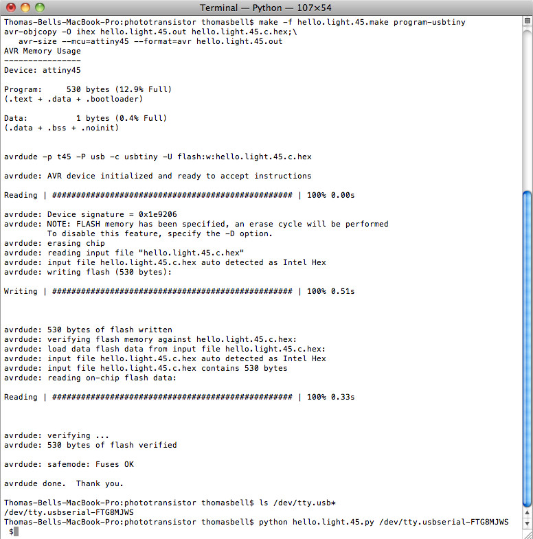
installed as per the instructions. I created a separate folder and copied across the .make file and c code and navigated to that folder within terminal and typed make -f hello.temp.45.make program-usbtiny to program the board.
|
Afterwards, I located the serial port by using the ls /dev/tty.usb*
within terminal and used the port number to use within Python.
After navigating to the relevant folder within terminal I tried to run
the Python file by typing: python hello.temp.45.py /dev/tty.usbserial-FT?????.
Unfortunately, I kept on getting an error as the NumPy module couldn't
be located within the Python libraries - this is due to the fact that
the program was written within Ubuntu and when working on Mac OS these
libraries aren't connected to Python within the OS. This posed a
problem as you have to be careful that the libraries get linked to the
correct Python version (you may have mulitple versions on your
computer) - I tried using MacPorts
first (which is a little like homebrew) but the version of Numpy and
SciPy didn't seem to connect to my current Python library.
Eventually after searching on the internet I found some page of links
which were relevant to my operating system (OSX 10.6.8) and my version
of Python (2.7) and once I downloaded these the Python application
worked correctly.
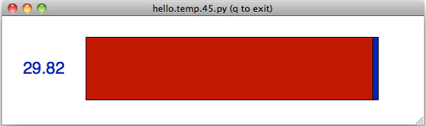
|
Unfortunately,
the sensor was stuck on this value. Another person undertaking
the course had exactly the same problem when using Python on this
board. I decided quickly that this was potentially a dead end or
a massive time sink, so i decided to program my other board and see if
this works. To see if this is a problem with the hardware or the
software. Update: Following class discussions, it was noted that
several people had the same problem but overcame it by reflowing the
solder joints. I performed the same routine and my board sprung
to life.cd ..
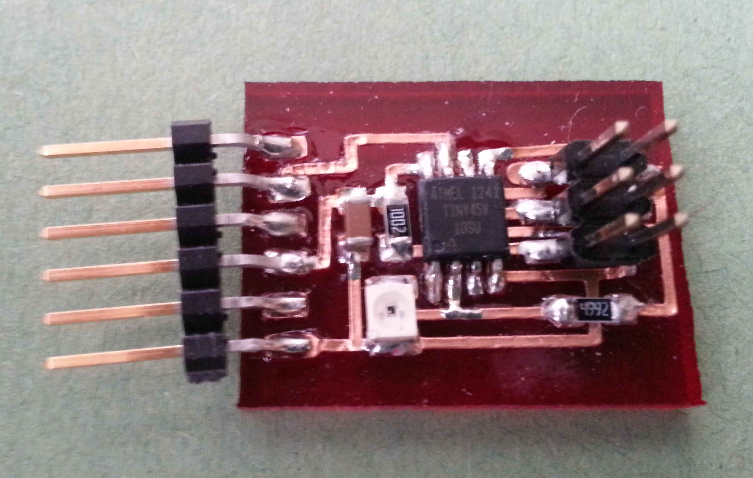
The hello light board programmed without a problem, although the vinyl
printer circuit was very weak and lifted at every opportunity.
Carefully I inserted the headers and the FTDI cable.
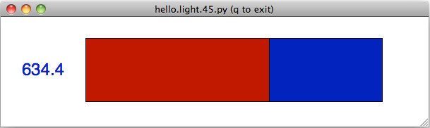
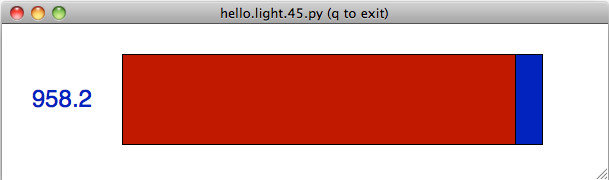
Ths
time I ran the Python program without any issue, as I had already
installed the previous libraries. The board picked up a variation
of light comoing into the device and displayed it accordingly.
The readings varied between 940 when I placed my finger over the
phototransistor and 680 for the background light level.
|