Final Project
Week 0: Digital Fabrication Principles and
Practices
Week 1:
Collaborative Technical Development, Documentation and Project
Management
Week 2:
Computer Aided Design
Week 3:
Computer Controlled Cutting
Week 4:
Electronics Production
Week 5:
3D Scanning and Printing
Week 6:
Electronics Design
Week 7:
Moulding and Casting
Week 8:
Embedded Programming
Week 9:
Computer Controlled Machining
Week 10:
Input Devices
Week 11:
Composites
Week 12:
Interface and Application Programming
Week 13:
Output Devices
Week 14:
Networking and Communications
Week 15:
Mechanical Design and Machine Design
Week 16:
Applications and Implications
Week 17:
Invention, Intellectual Property and Income
Week 18:
Project Development
Week 19:
Final Project Presentation
|
Output Devices
The project for this week was to create an output device and program to make it do something. From the lecture notes
there were varying differing output examples that we could experiment
with, because my knowledge and understanding of electronics is fairly
minimal I decided to try to construct and program the LED Array
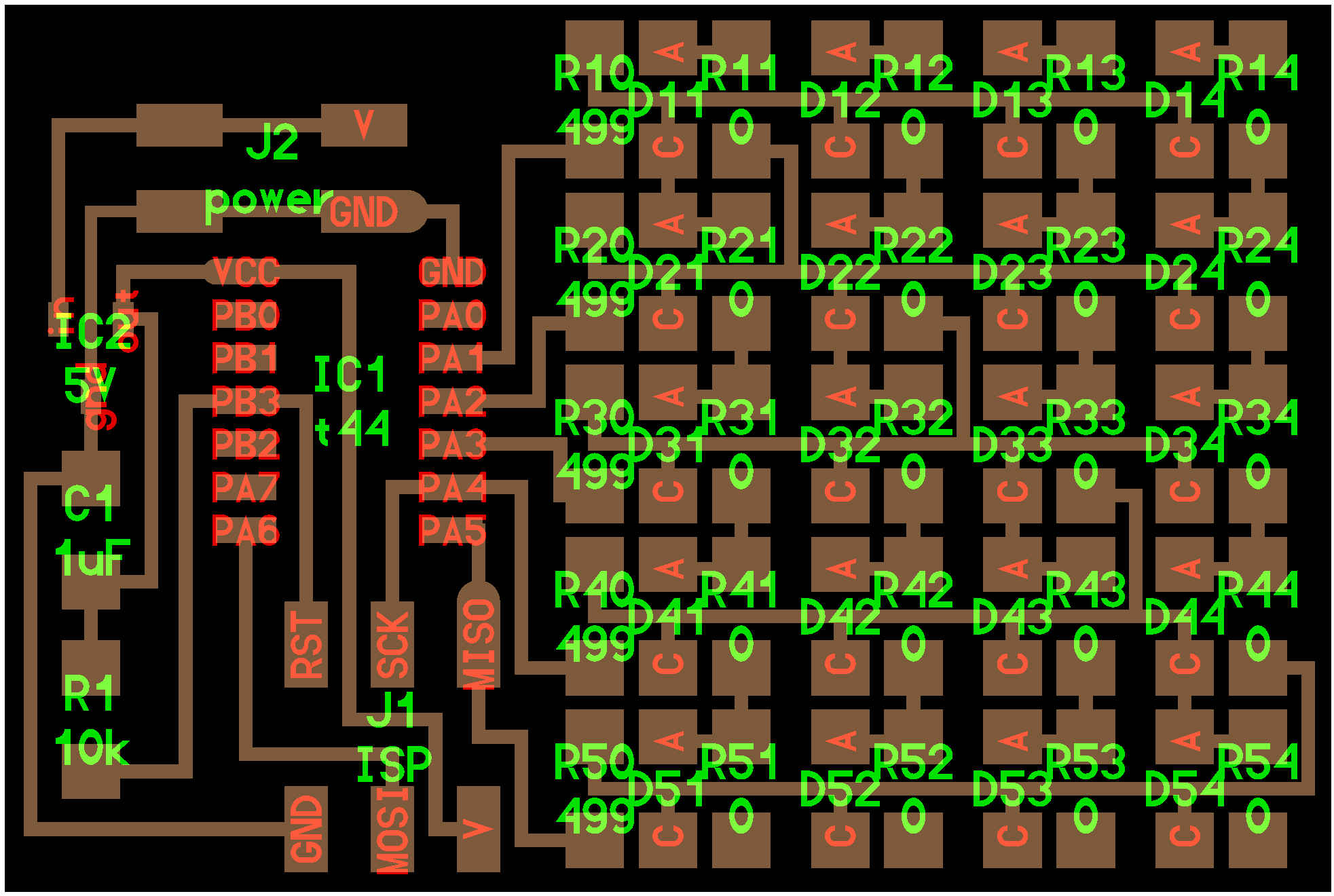
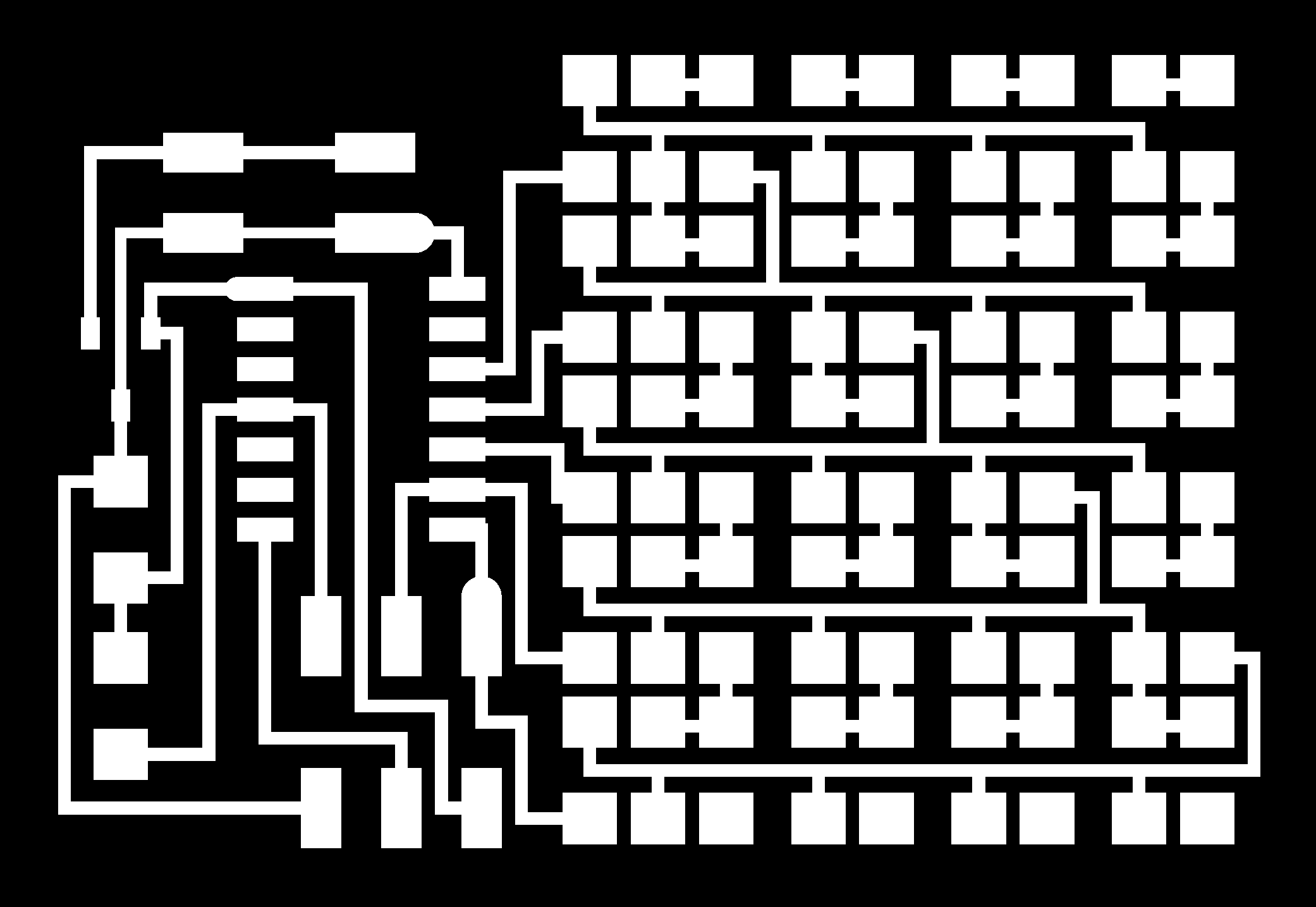
example. Using the trace .png
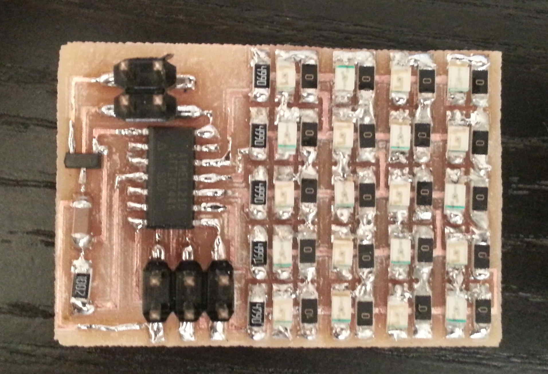
for the LED array example, I milled out the board using the same
workflow that we had used previous in weeks. Additionally because
the board was fairly tightly packed I found it benefical to ensure that
any remaining unused and unmilled bits of copper trace were removed
with a craft knife.
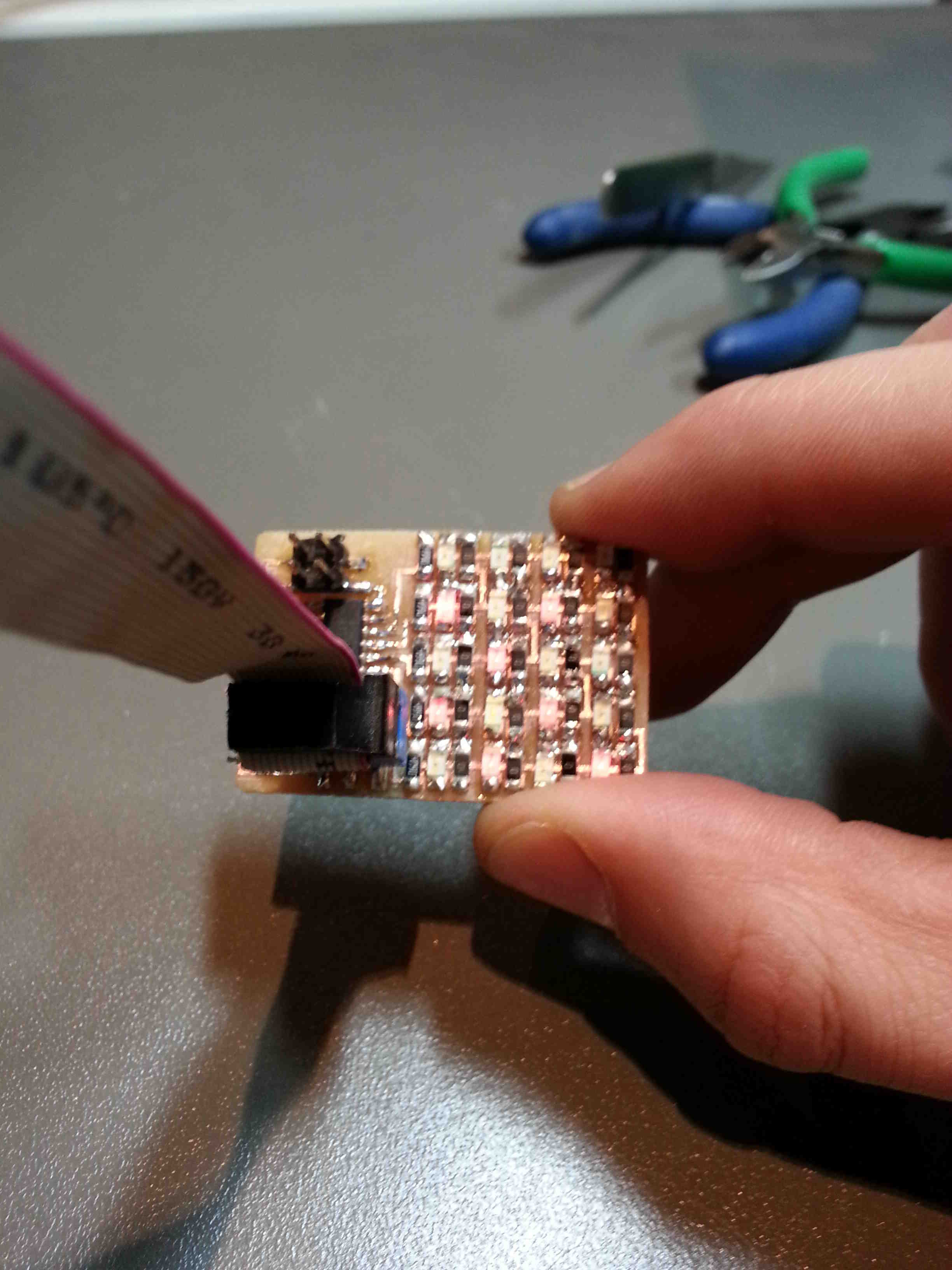
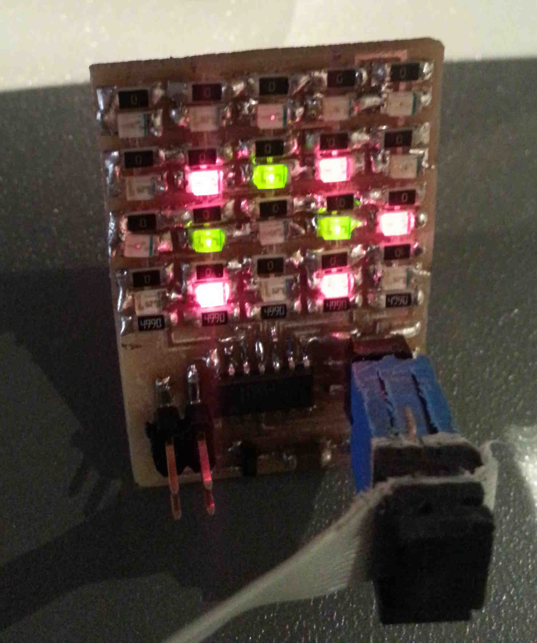
LED Array:
I carefully
began stuffing the board ensure that the anode and the cathodes of the
LED's was correctly aligned with the layout of the board.
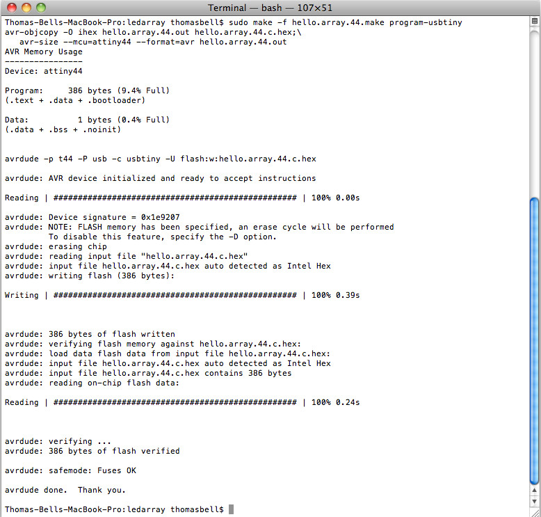
Once the board was fully stuffed I programmed the board using my
FabISP, I was really surprised that it worked first time because of all
the precise soldering necessary for all the LED's.
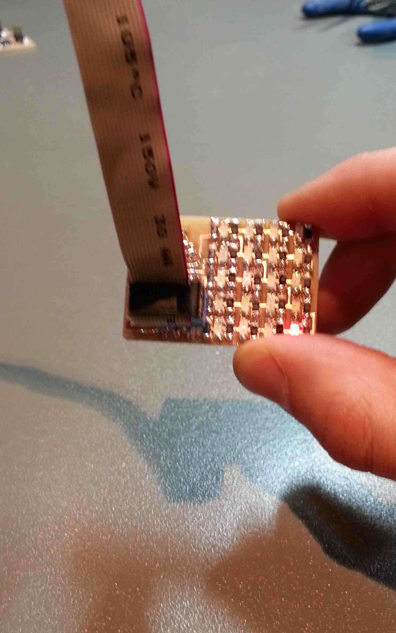
I soon found the reason why it worked first time because when I
uploaded the first program a line of LED's did not light up. On
closer inspection I realised that one of the LED's was orientated in
the wrong direction and I noticed that this didn't affect the other
lines because it was placed in parallel and thus only affected the
LED's linked directly to it. Similarly, the programming of the
board was not influenced by the LED arrangements so as long as the
ATtiny44 was position and soldered correctly the board would program
without any issues.
I removed the incorrectly soldered LED and correctly realigned it - once I had done this the board and all the LED's worked.
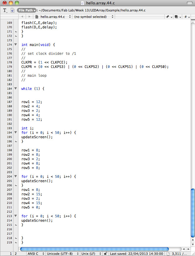
Programming LED Array:
The next part of the assignment required me to reprogram the board. I studied the example C code
that I used to test if the board was working correctly and began
manipulating the code. I expanded the C code to select which LED
were lit in a cycle, the expanded element of the C code is shown below.
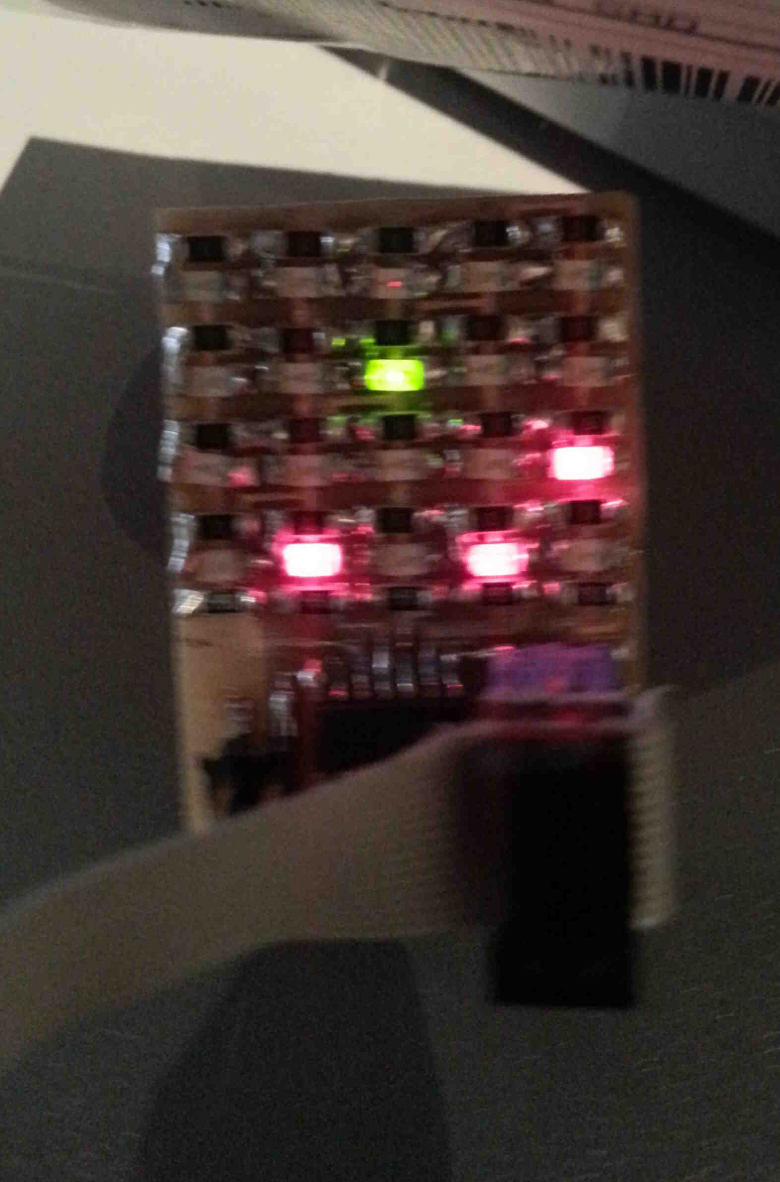
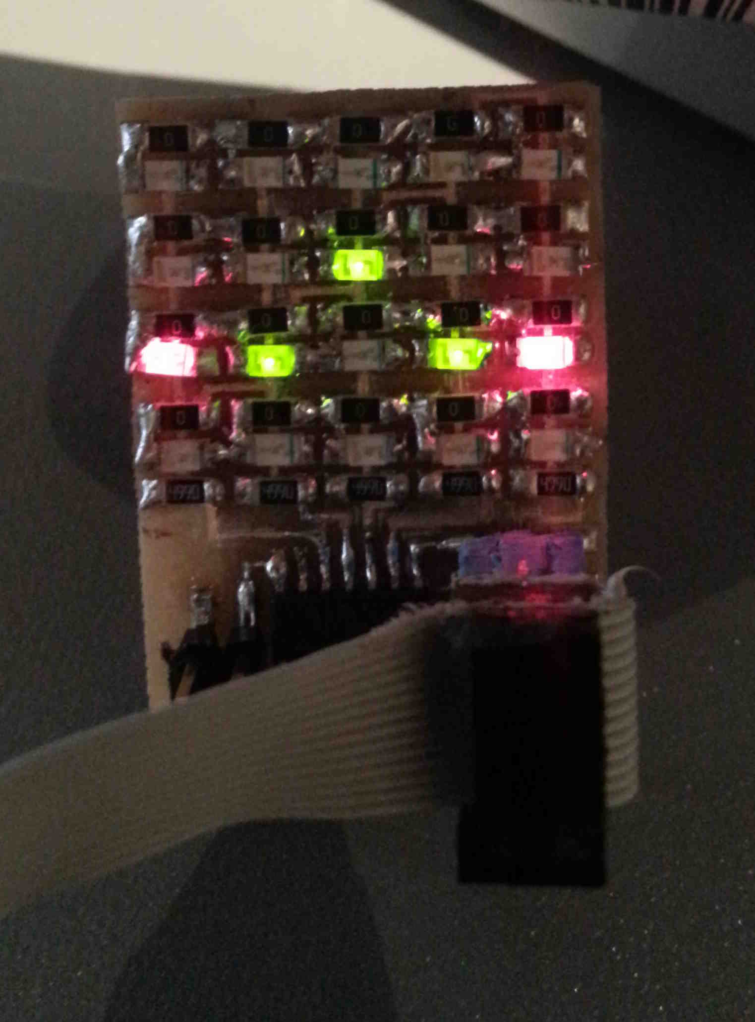
Here is a picture showing each stage of the LED array cycle.
|