Final Project
Week 0: Digital Fabrication Principles and
Practices
Week 1:
Collaborative Technical Development, Documentation and Project
Management
Week 2:
Computer Aided Design
Week 3:
Computer Controlled Cutting
Week 4:
Electronics Production
Week 5:
3D Scanning and Printing
Week 6:
Electronics Design
Week 7:
Moulding and Casting
Week 8:
Embedded Programming
Week 9:
Computer Controlled Machining
Week 10:
Input Devices
Week 11:
Composites
Week 12:
Interface and Application Programming
Week 13:
Output Devices
Week 14:
Networking and Communications
Week 15:
Mechanical Design and Machine Design
Week 16:
Applications and Implications
Week 17:
Invention, Intellectual Property and Income
Week 18:
Project Development
Week 19:
Final Project Presentation
|
3D Scanning and Printing
This
weeks lecture provided an introduction to 3D scanning and printing and
the necessary programs used to enable you to do these process.
3D Scanning:
Initially
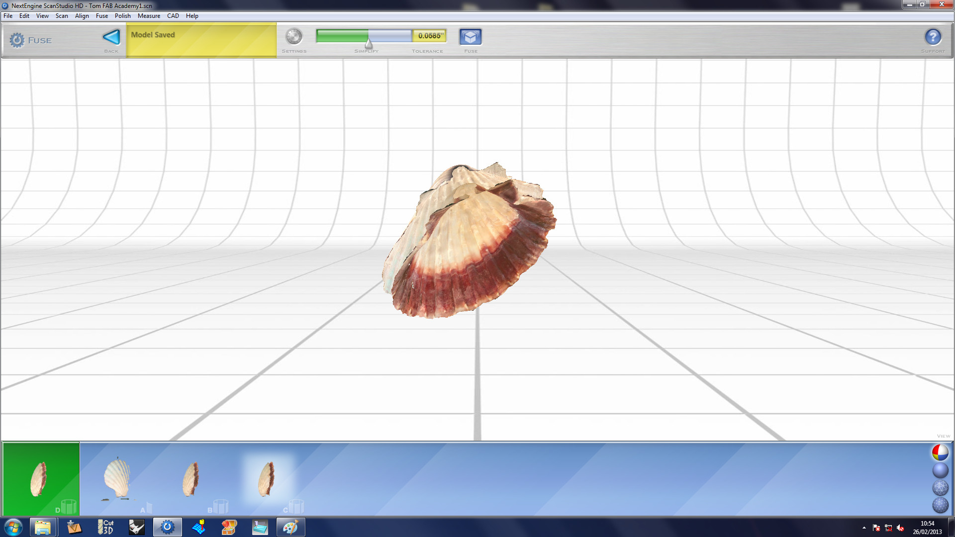
I started with the 3D scanning part of the assignmment. Here at
the MakLab the available 3D scanning machine was the Next Engine, for
observing other people scanning objects I decided to go for an object
that had a matte finish in order to get good clarity for my
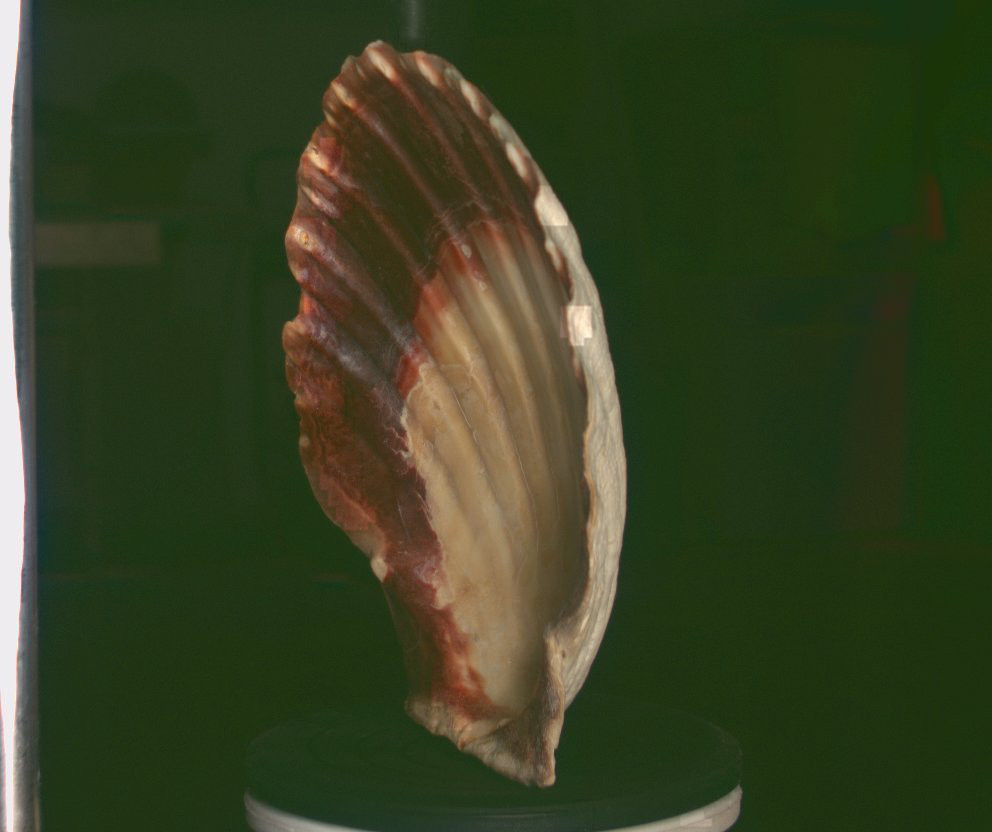
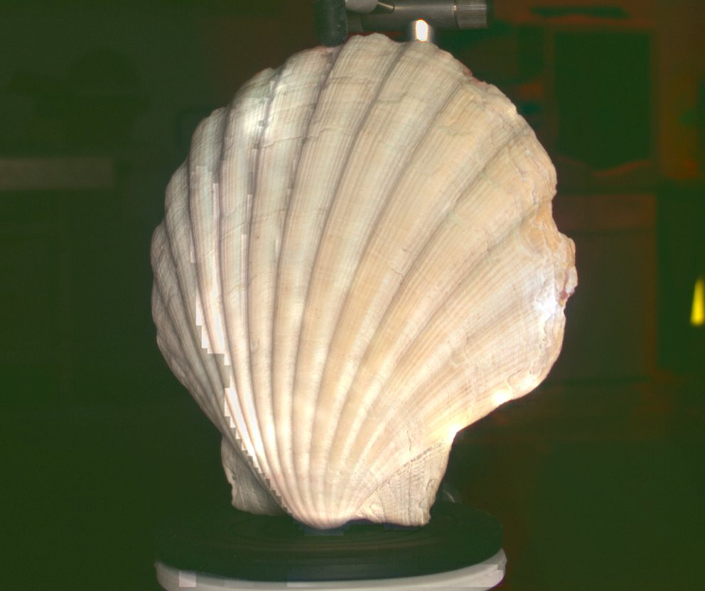
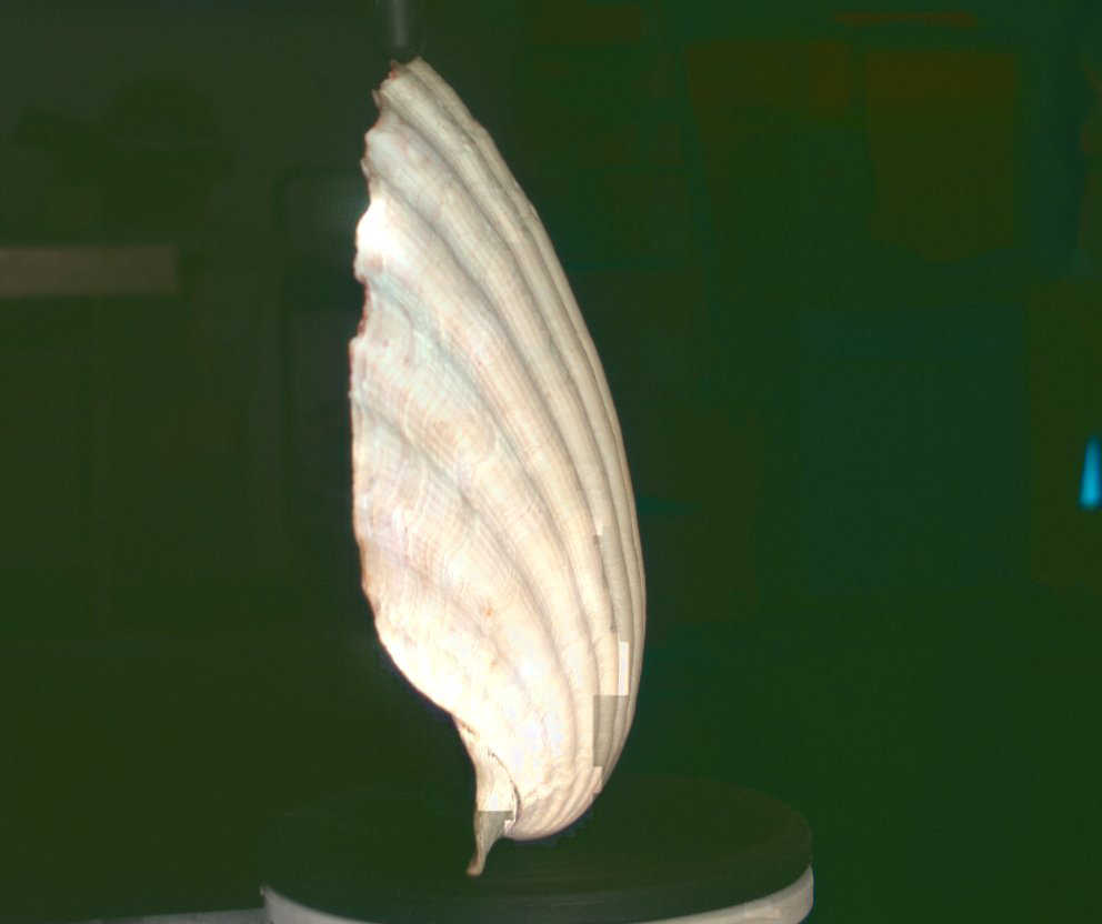
object. Looking I found a scallop shell, that I thought would be
interesting as it had a highly textured finish and a myriad of colours
on the underside.
Due to the fact that the
rubber fixings that were to fix the object were in white, I removed
them and placed corresponding black rubber pads so that there was
enough contrast between the predominately white shell and the object
scanning mounting to enable me to correctly identify each and remove
the necessary parts after the scan had finished. The properitary
programming supplied for scanning was very easy to use to enable the
scanning. It is very wise to conduct a trial scan on just one
face/orientation before commencing the full 3D scan to ensure the
necessary clarity, detail is achieved and whether or not the object
needs dusting to allow for the object to be scanned properly.
Another element that should be checked is the distance of the object
from the scanner to ensure that the object is within the optimal range
for the scanning type, a handy diagram within the program will show you
the correct depth, also it is wise to check that when the object
rotates 360 degrees it stay within the area you selected for scanning.
Use the test has been undertaken, you can conduct the full scan (the
length of which will vary with the scan density and quality).
During the scanning process, the program takes .jpg pictures at the
varying orientations, I have imported a few below to get an idea of the
object that is being scanned.
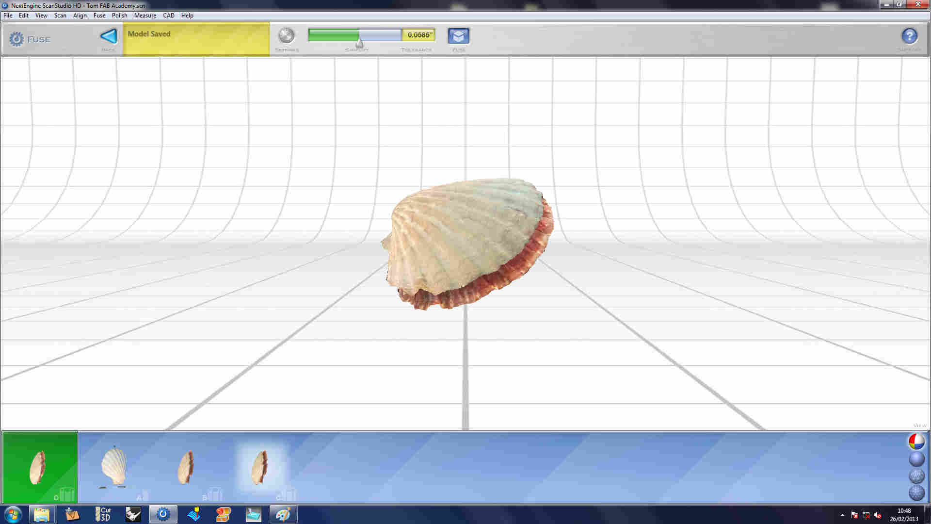
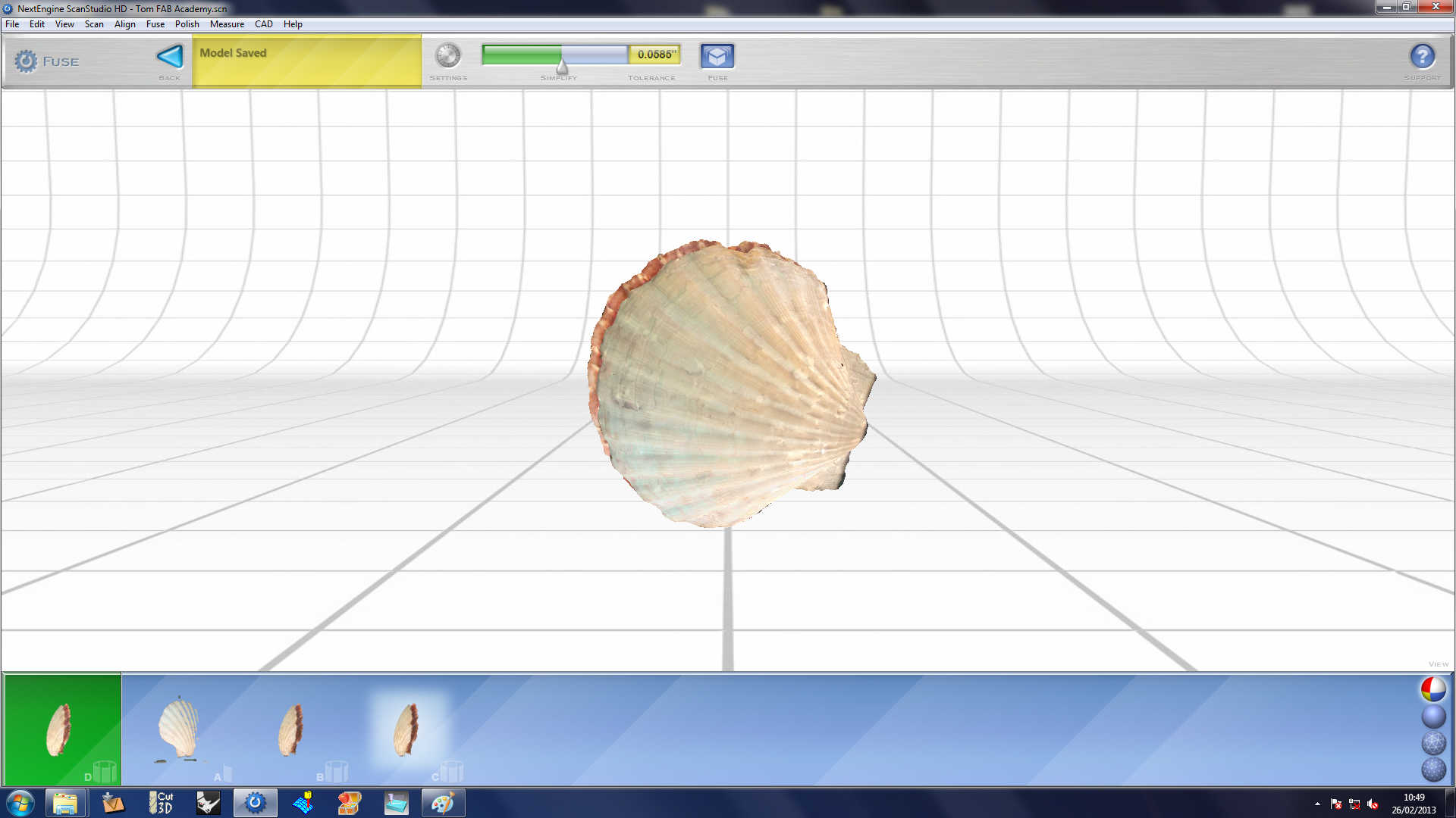
Once
the scan had completed the program showed a 3D model of the shell,
unfortunately it seemed to be formed of two faces that were set
independent from each other. Using the scanning package, trimed
off the restrainted pads (that were attached to the turntable) and I
tried the smooth command, but this didn't join the two faces of the
shell, it just smoothed the surface of the connected wireframed
segments.
Failing
this I tried the 'fuse' command but this process didn't work
either. I believe it is because the edge of the shell was too
thin for the scan settings and the scanner did not pick up the edge of
the shell and thereby failed to connected the two seemingly seperate
entities.
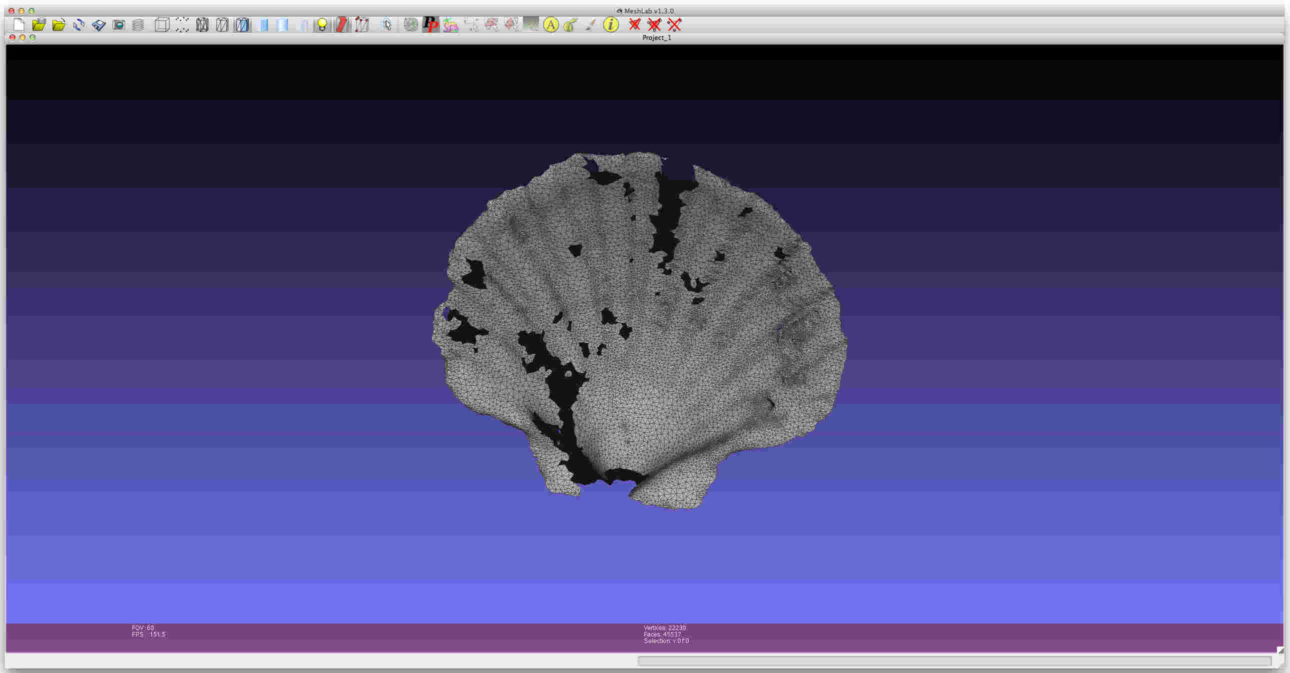
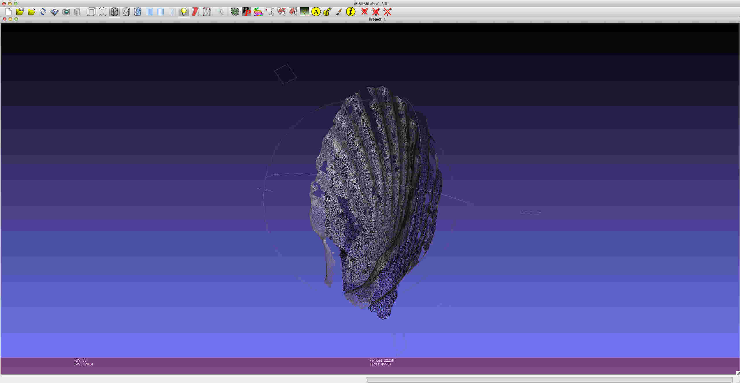
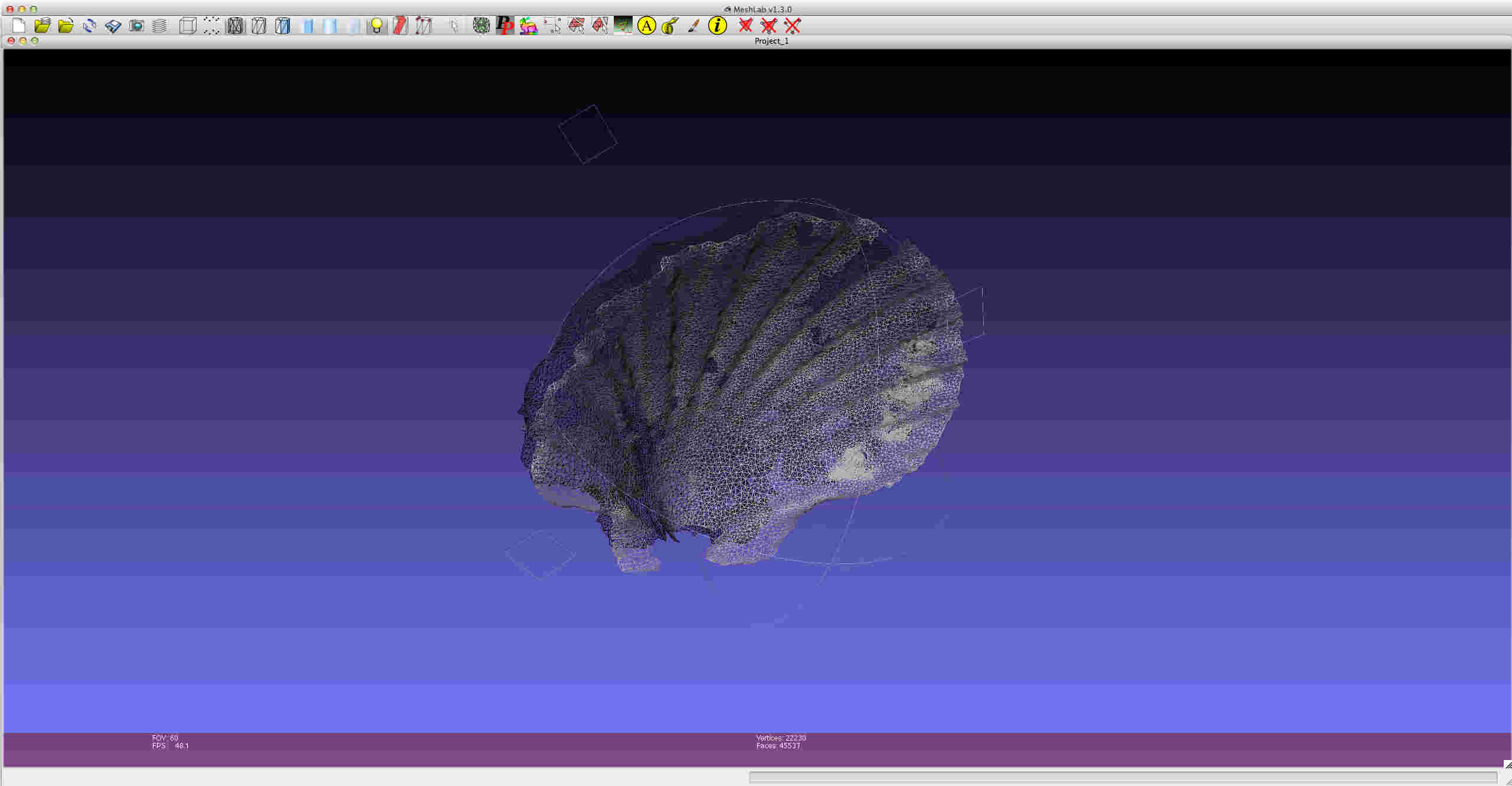
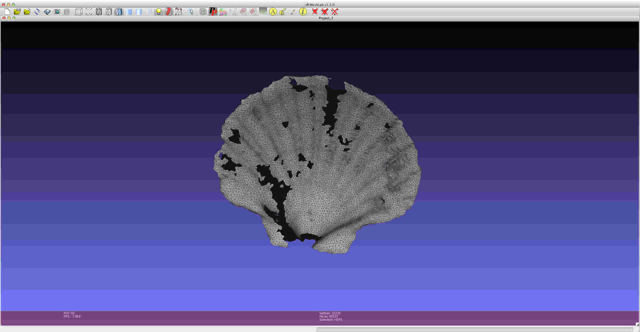
Thereby
the only option was to try and repair the wireframe manually, I saved
the model as a .stl and opened it with the program MeshLab to see
whether this was feasible and then I could attempt to 3D print a scaled
down version of the shell. Unfortunately, the holes in the wire
frame were too many to do manually in the time allocated, so I decided
to move onto the 3D printing section of the assignment.
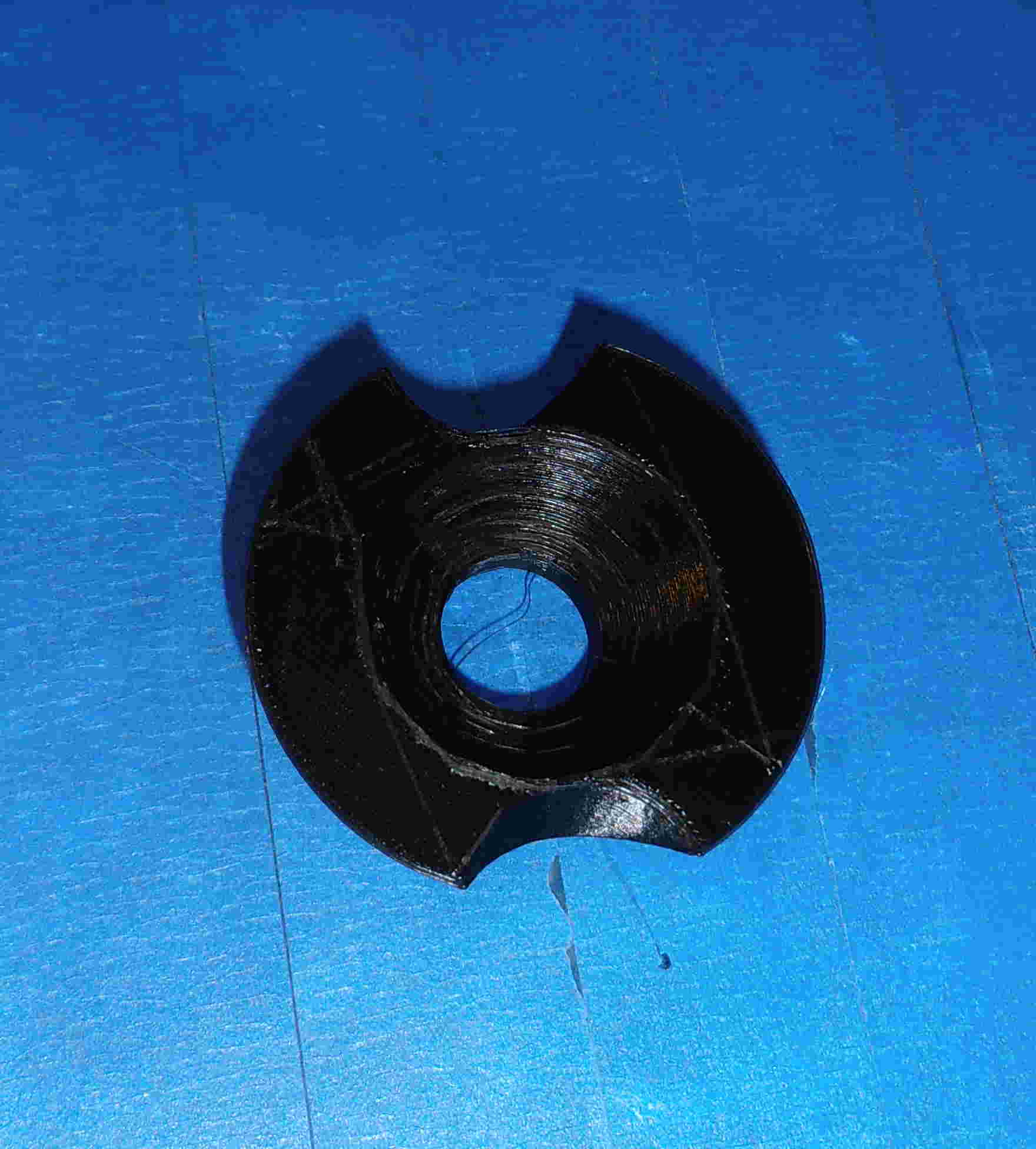
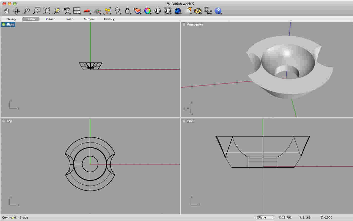
3D Printing:
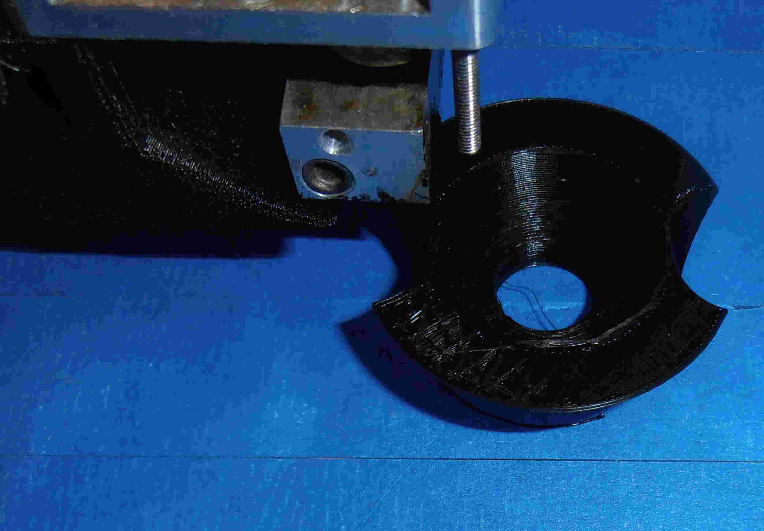
For
the 3D printing section of the assignment, made a simple model with
solids in Rhino, to form a shape to print. I used several solids
with some boolean functions to create a interesting shape, that are
still small enough to print within a reasonable timescale.
|
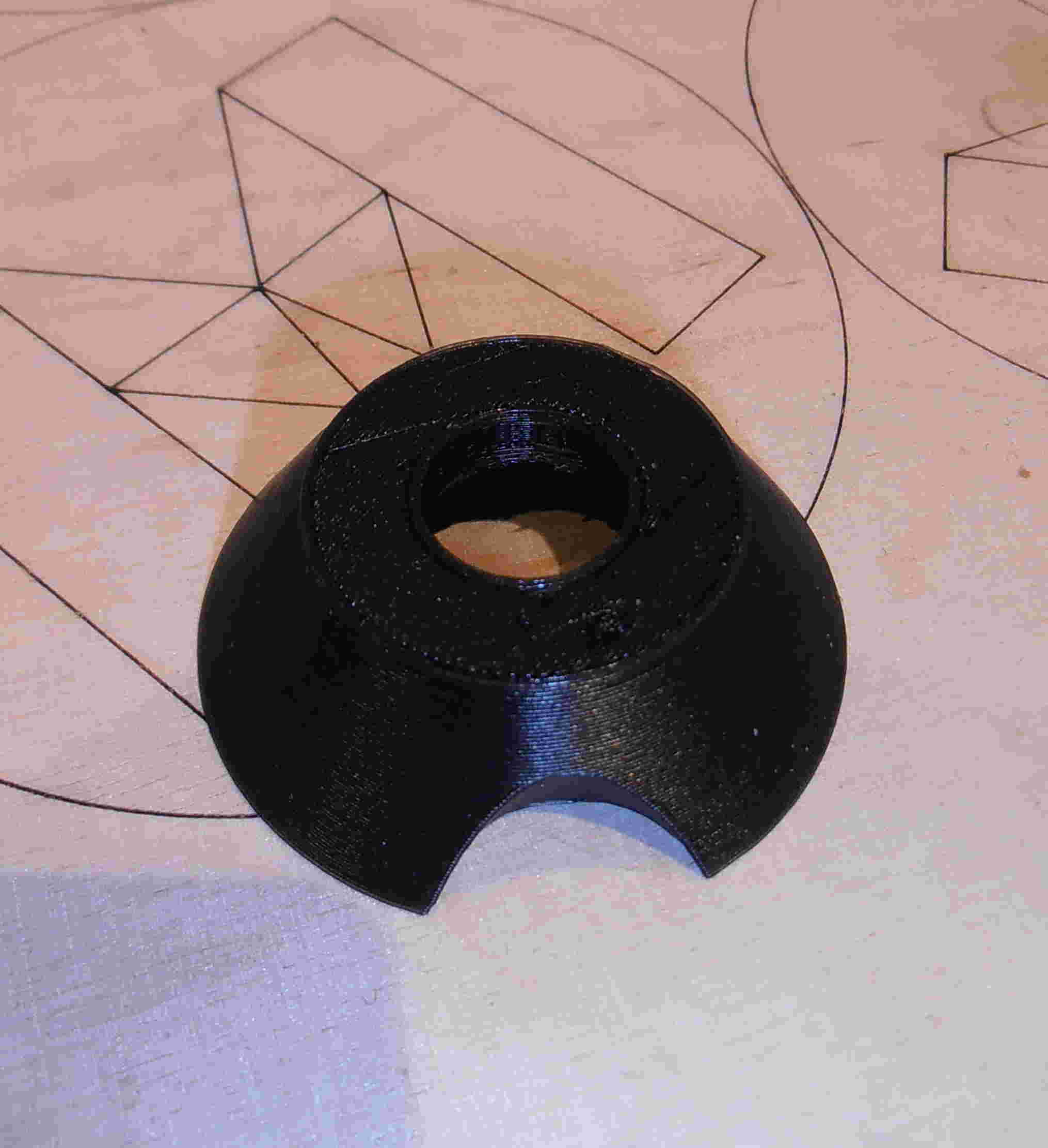
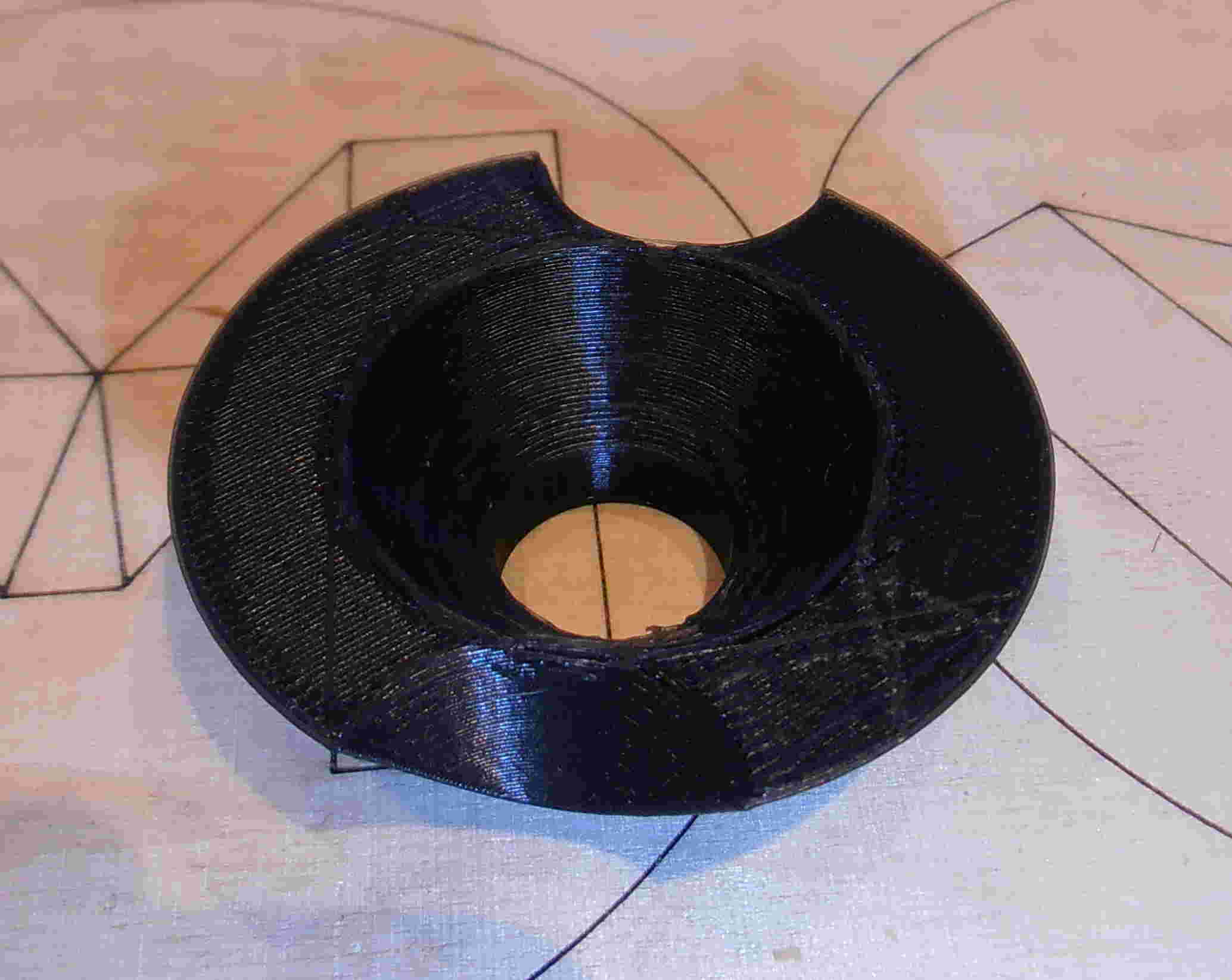
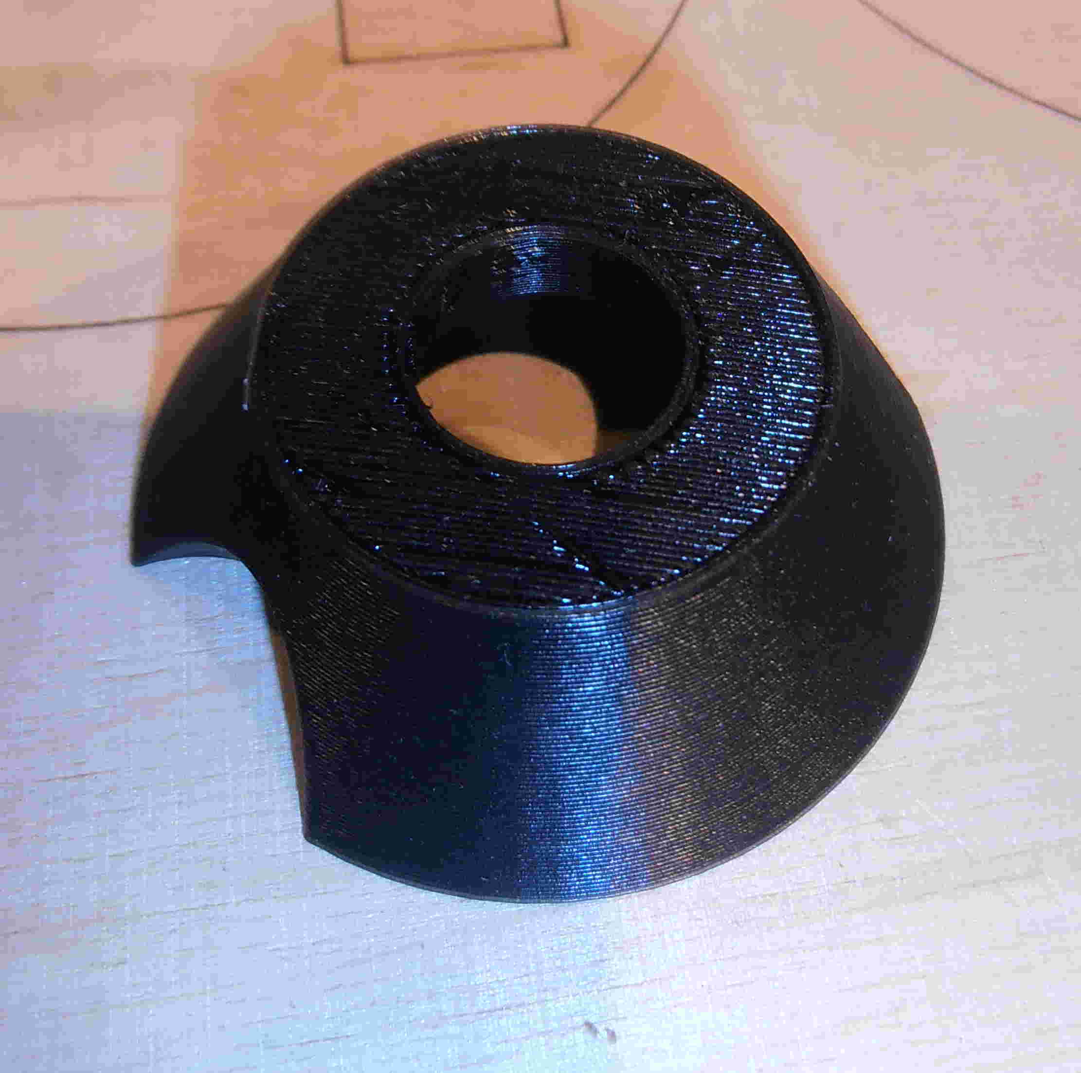
I then
exported the file as a .stl model that created a 3D file, I then opened
the file in MeshLab to check whether there were any holes in the
wireframe that will cause issues with the 3D print. Luckily there
were no holes in the wireframe, so I imported the file into Cura (the
program here that is used for creating printable 3D files). Cura
gives a representation of the base of the 3D printer, from which you
can scale the project easily using the embedded scaling tool.
Once you are happy with the size and the density (i.e the amount of
internal fill) of the print you then you can export it to a
G-code. The G-code, is a horizontal by horizontal slice guide for
the laser printer to follow and the program will give you an estimated
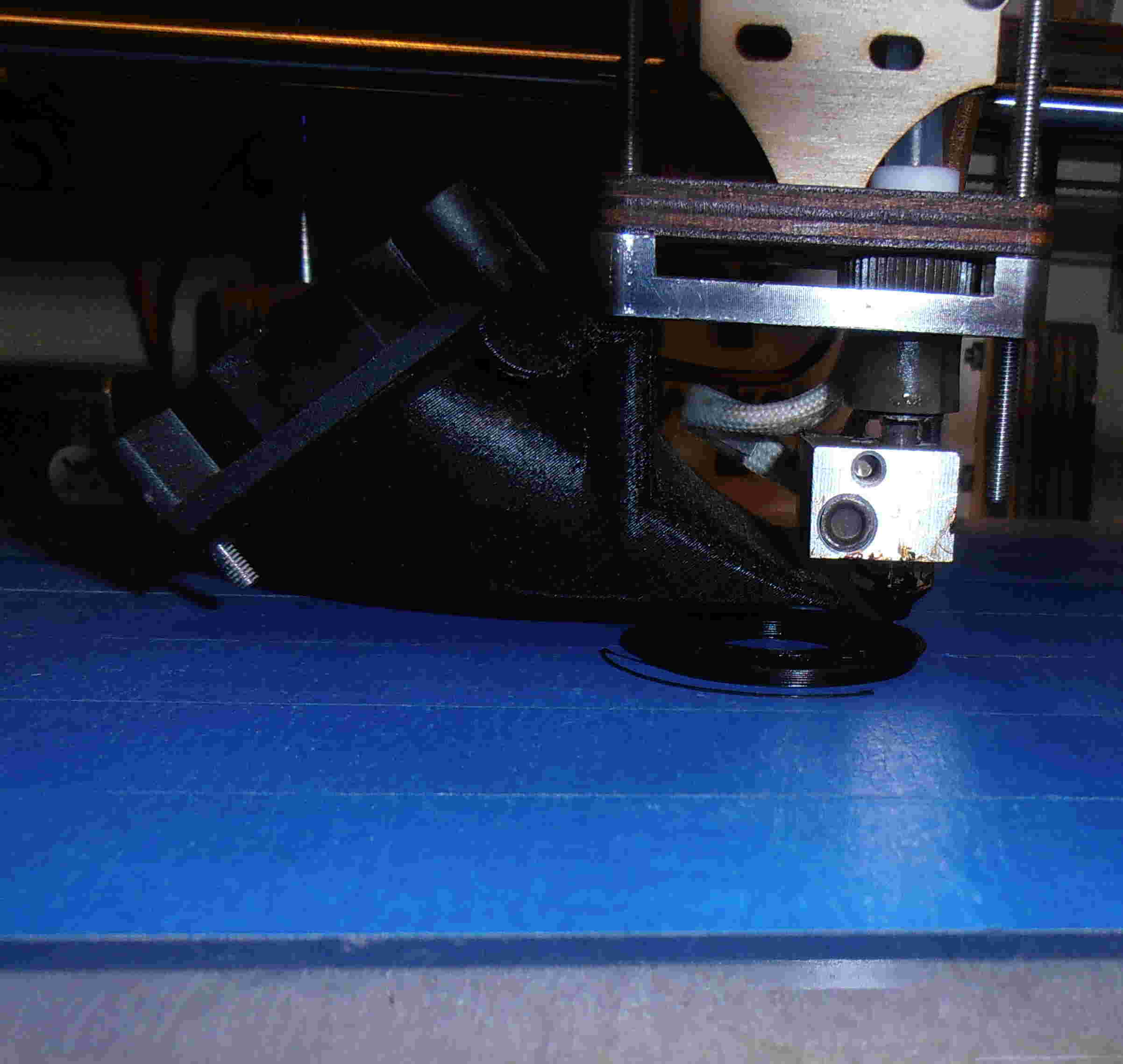
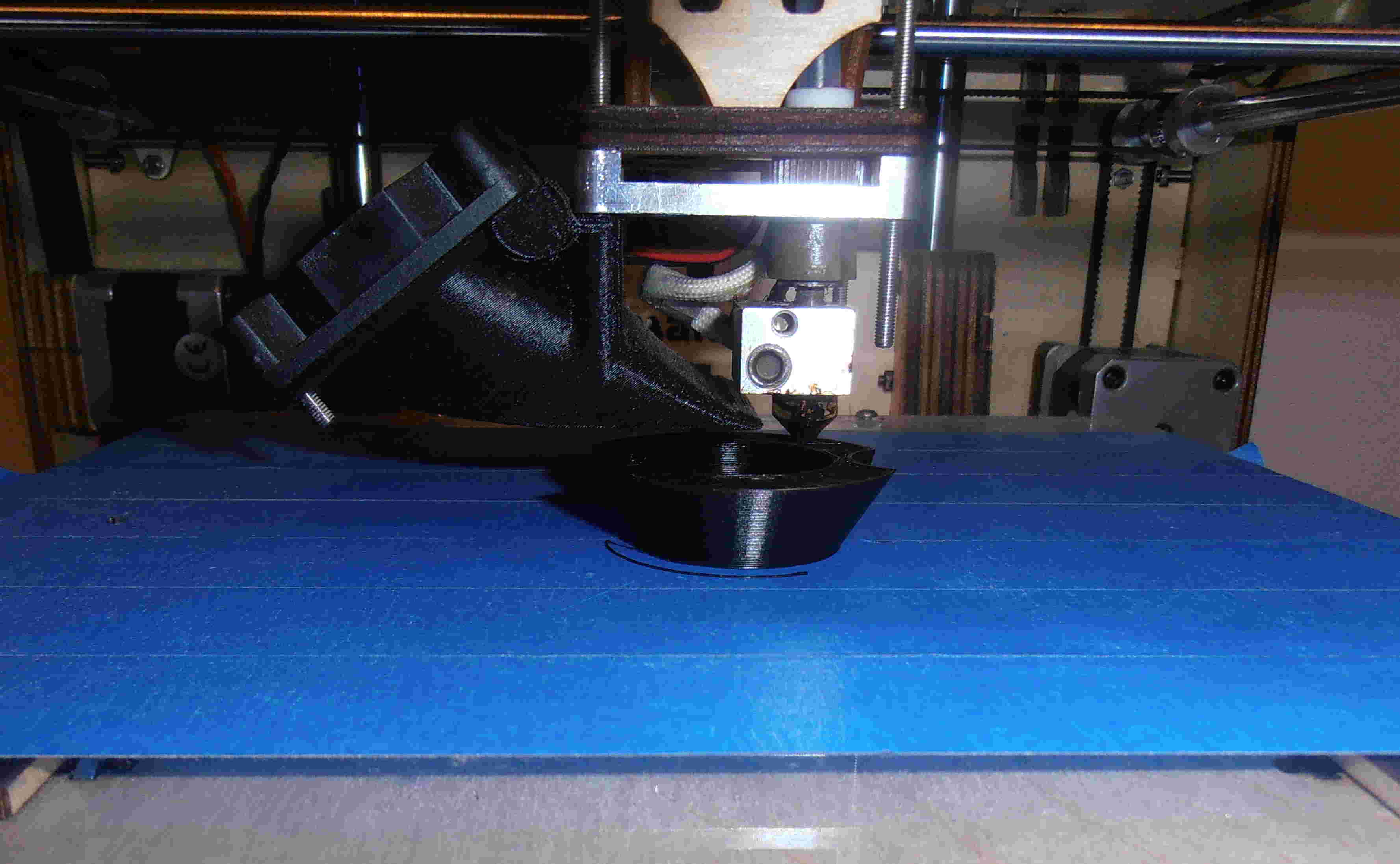
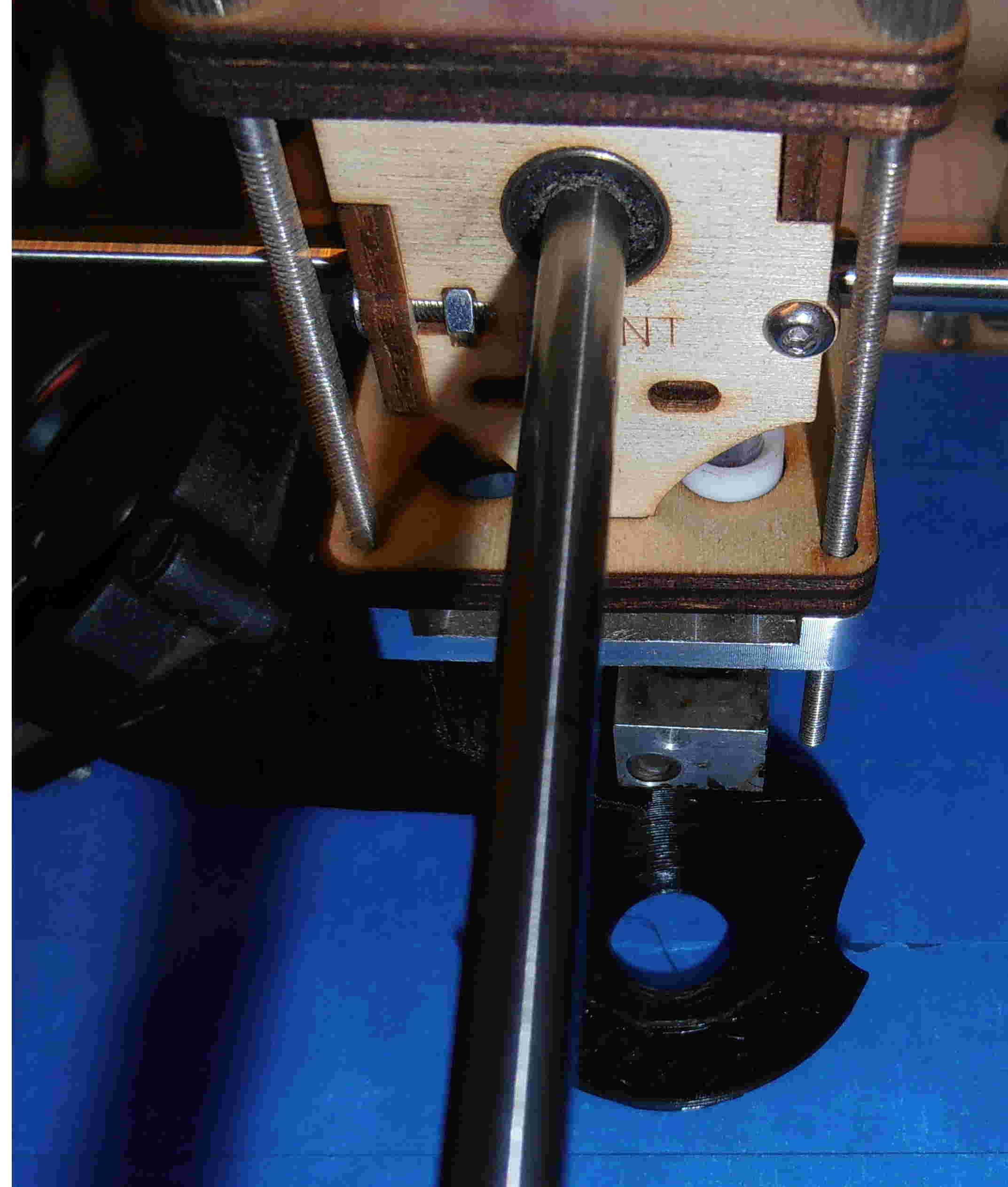
time to completion - my project took in the region of 20-25mins.
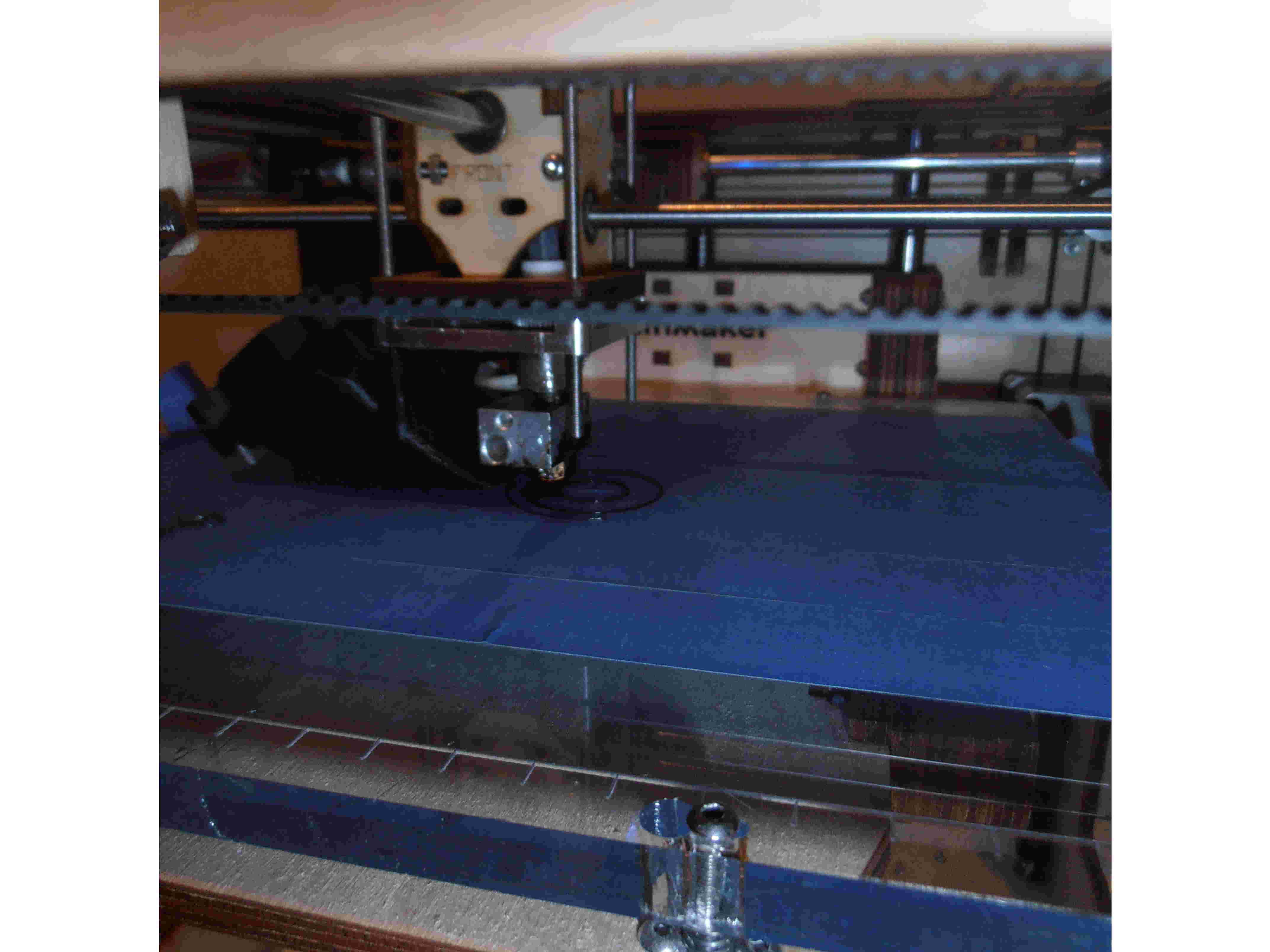
After the G-code is created it is then placed on a SD card and inserted
into the machine for printing. The whole process was effortless
and yielded fairly good results, although at the beginning, you should
keep an eye on the noozle to ensure that the initial outline does not
foul the 3D print.
|