Final Project
Week 0: Digital Fabrication Principles and
Practices
Week 1:
Collaborative Technical Development, Documentation and Project
Management
Week 2:
Computer Aided Design
Week 3:
Computer Controlled Cutting
Week 4:
Electronics Production
Week 5:
3D Scanning and Printing
Week 6:
Electronics Design
Week 7:
Moulding and Casting
Week 8:
Embedded Programming
Week 9:
Computer Controlled Machining
Week 10:
Input Devices
Week 11:
Composites
Week 12:
Interface and Application Programming
Week 13:
Output Devices
Week 14:
Networking and Communications
Week 15:
Mechanical Design and Machine Design
Week 16:
Applications and Implications
Week 17:
Invention, Intellectual Property and Income
Week 18:
Project Development
Week 19:
Final Project Presentation
|
Computer Controlled Cutting
This
week the assignment is to create a press fit construction kit using
computer controlled cutting technique. The principle behind
creating these kits is to form a series of 2D building blocks that can
be friction fitted to one another using manual force to develop varying
3D designs.
Preliminary design:
Over the festive period I spent time building race tracks and ramps
with my young nephew to catapult matchbox cars. I noticed how limited the
variations in these tracks were and the scope for creativity was
blunted by the lack of expansion available or the predefined routes of
these bespoke pieces that lack structural form. The idea is to
create a race track that can be developed and expanded using press fit
construction that can be assured of structural integrity (provided that
it was built correctly) whilst being developed and manufactured cheaply.
Parametric design:
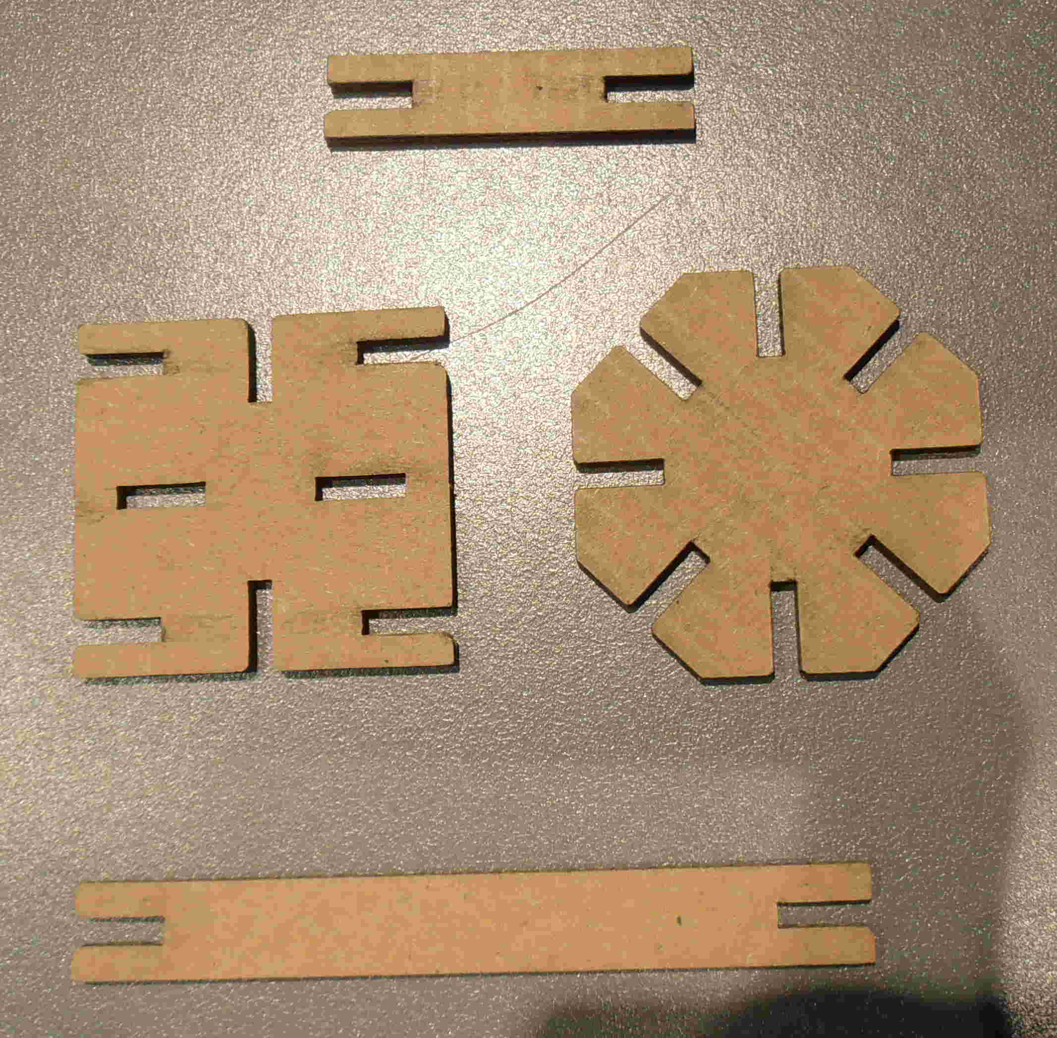
Firstly,
I decided upon which material I was going to use for my snap fixed
construction kit. For this I found a sheet of fairly robust 3mm
thick cardboard in the laboratory and started designing a simple shape to ascertain the
parameters of the snap fit construction kit for this particular piece
of cardboard. The
material chosen will alter the ability and the tolerances for a
friction fit to be undertaken between the pieces. To achieve a fast and effective way of
altering the shapes to adhere to these tolerances of different materials it is necessary to
develop the design in a parametric manner, whereby the whole design
will be altered according to a single change in one element of the
design. The tolerances of the press fit notches can then be
iteratively developed quickly and effectively depending on the material
type and the thicknesses available.
The ability of the pieces to snap fit was iteratively developed using
the parametric design processes described to alter the notch width of all the
pieces incrementally at the same time throughout the entire design.
Cutting the shapes out of 3mm thick cardboard a 2.5mm wide notch seemed
to give the best compromise of friction and build-ability with small
chamfers at the edge of the notch to aid in locating the pieces nicely
to one another.
To create a simplistic parametric design I initially started using the
clone function in Inkscape, but found that altering the design was a
bit tricky to accomplish. Using an educational version of Autocad
2012 on the Mac I used to parametric facility available to achieve
this, it wasn't very intuitive but after viewing several tutorial
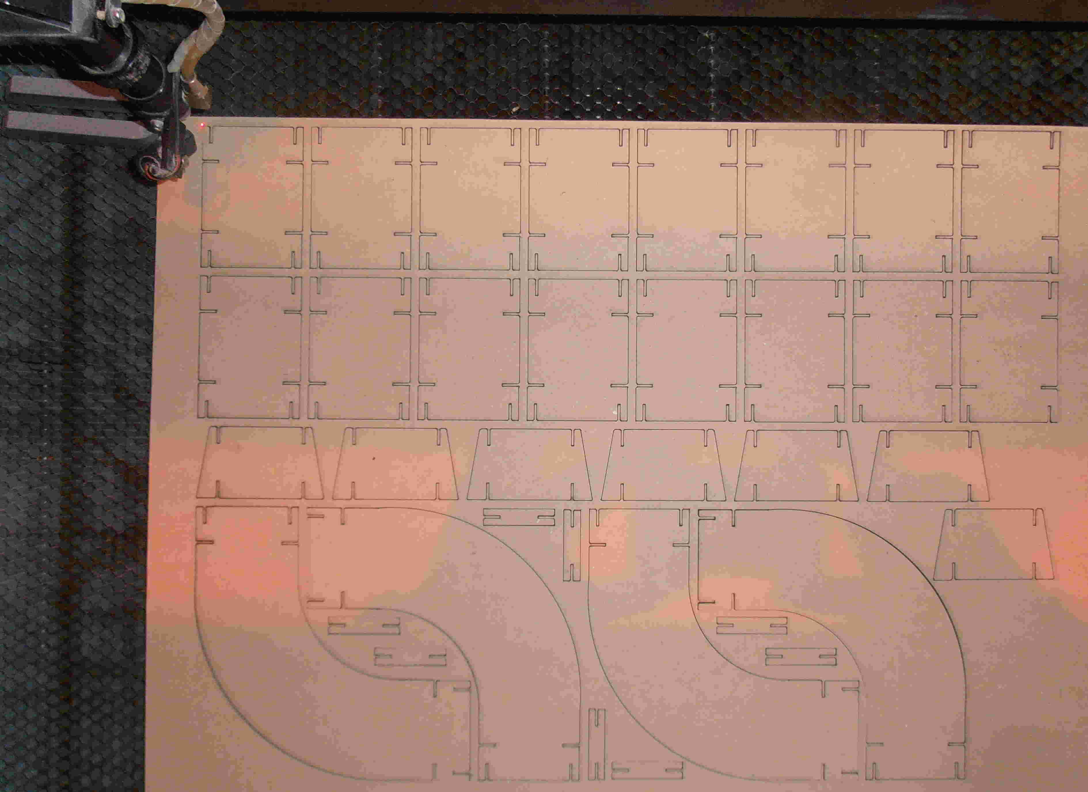
videos I could do what I needed. After developing the shapes, I
exported the file to a .dxf and uploaded it to the laser cut program to
begin the cutting process. The laser power and speed can be alter
depending on the material and for the laser at this laboratory the
speed was set at 55 and the power at 70 to achieve a clean and
effective cut through the material.
Fundamental design:
I manufactured several small batches of the prototype pieces to assure
that the pieces fitted together neatly. All the tolerances that I
had included for in the preliminary design allowed for the pieces to
fit neatly without impinging one another.
I also included a hole in the primary piece to allow for a through fit
to take place but the tolerances of the hole wouldn't allow for easy
installation in conduction with a stable secure fit, so during the
continued development of the design this feature would be omitted.
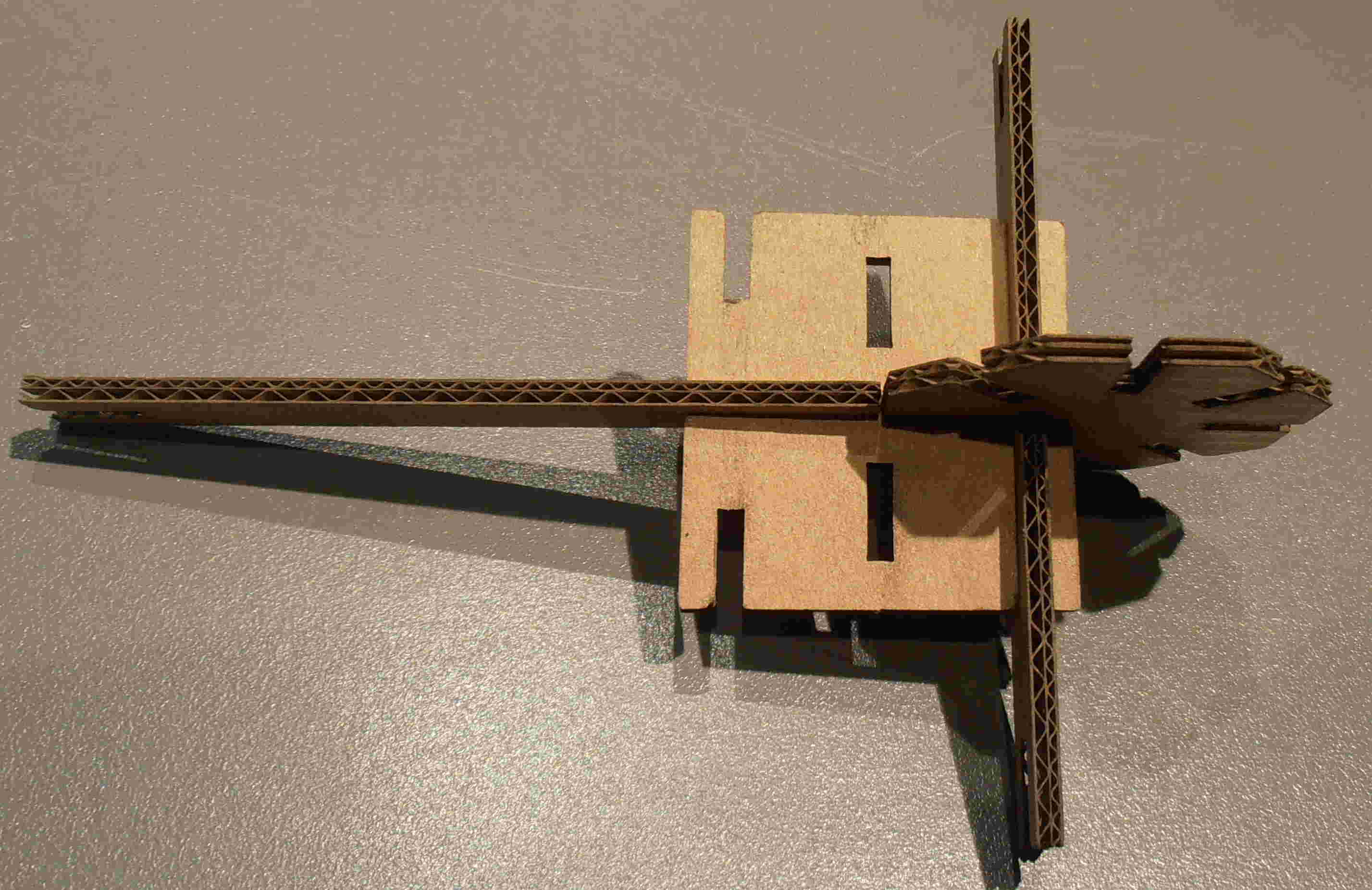
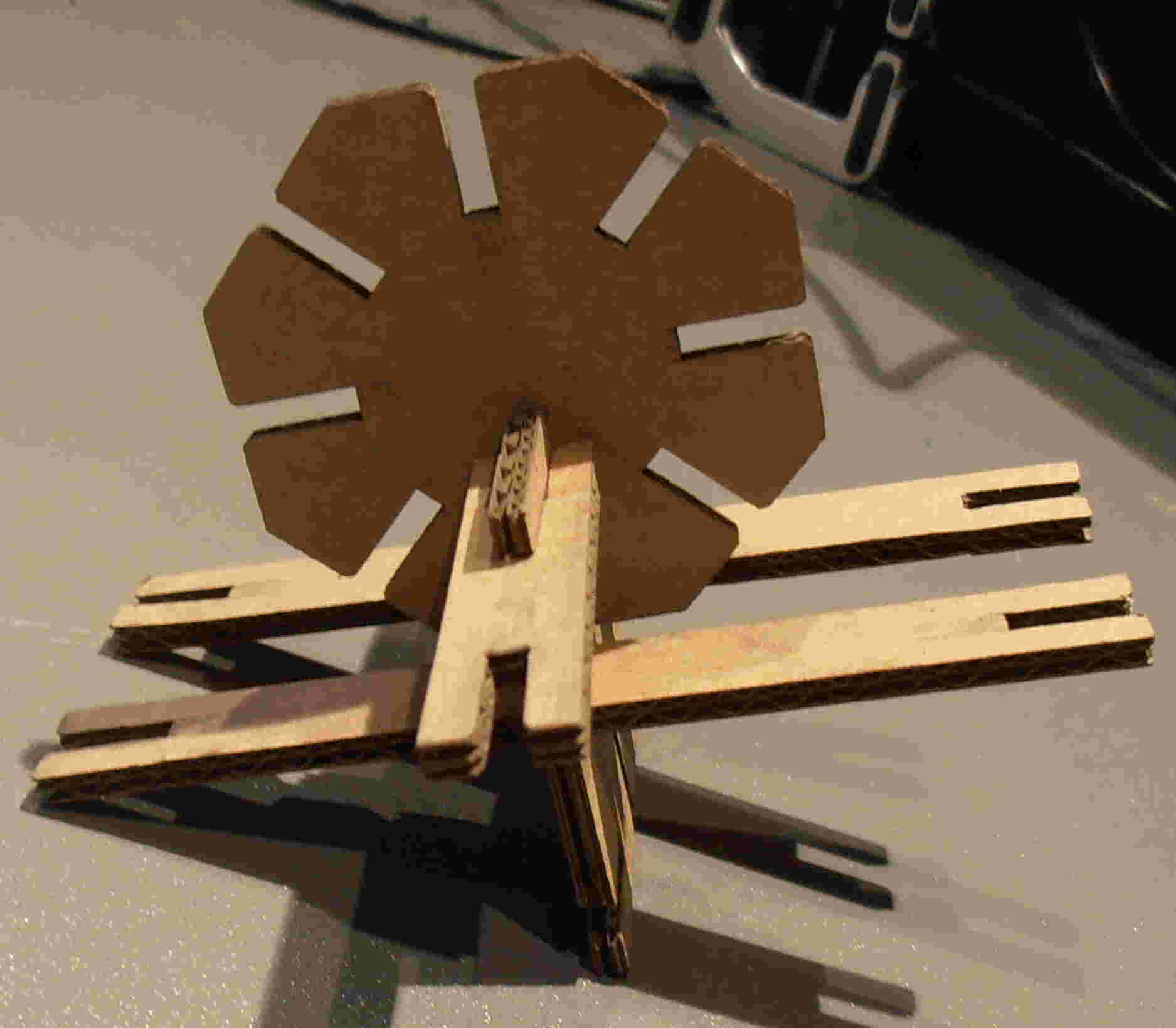
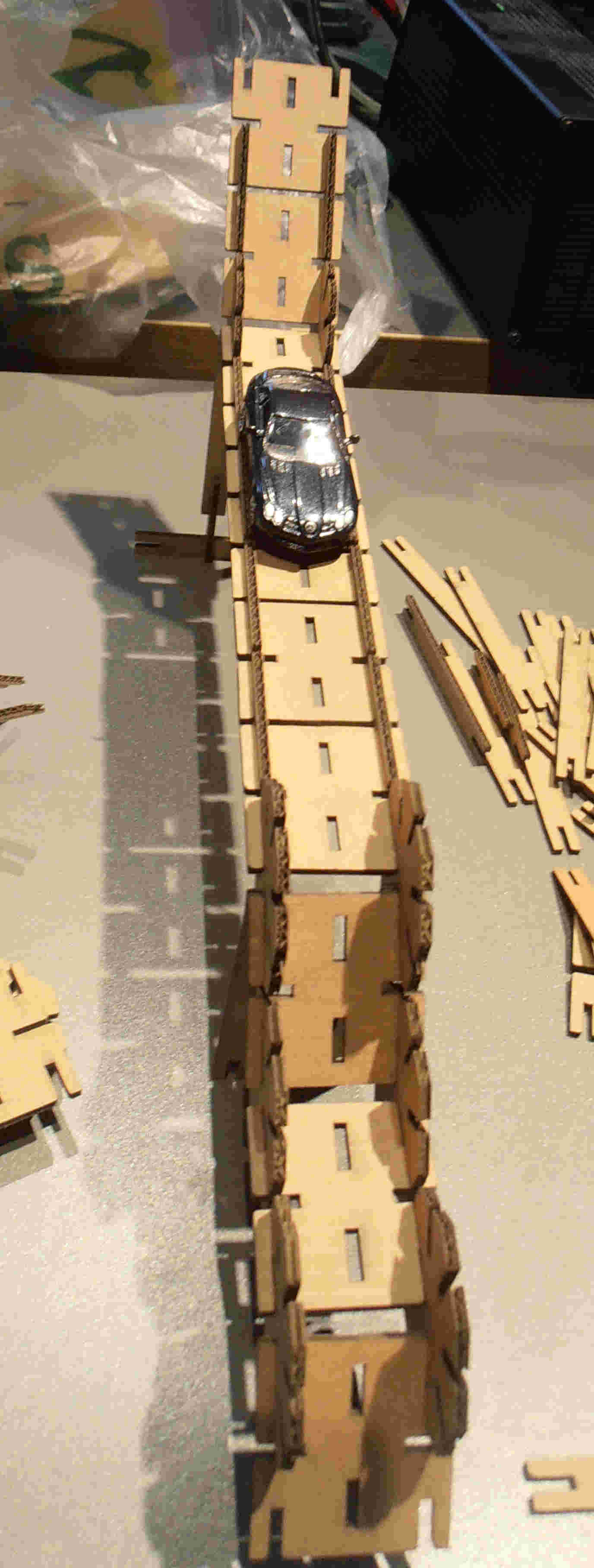
From this small batch, tried to create a simple structure to try and
see any inadequacies within the design and test how everything fitted
together. The pieces fitted together well, but their were several
flaws in the overall design. The clearance allowed for the
prototype car was to small to allow the car to run freely down the
track and the design was not stable due to a lack of base pieces
to support the super structure soundly. Furthermore there was an
inability of the track to turn corners without a curve piece of track,
additionally the angles of the tracks were restrained by the polygonal
piece which could be developed to allow altering gradients as 45
degrees is only gradient at present.
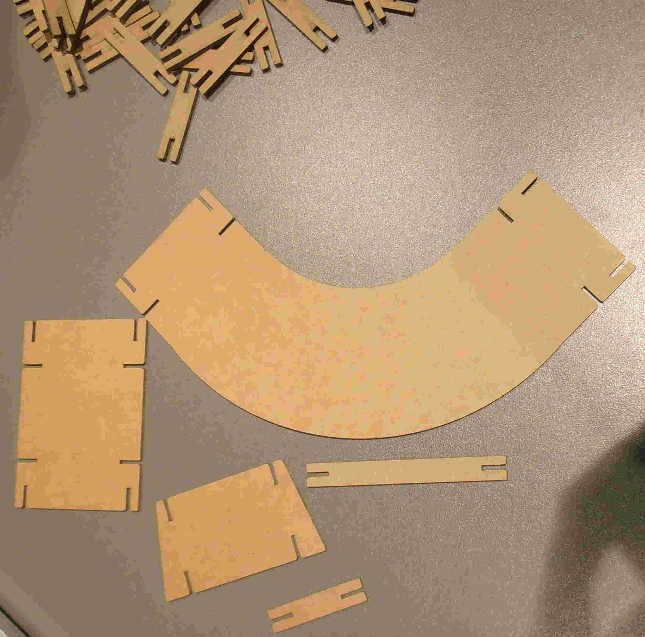
Design development:
Developing the design from the informed testing, curved pieces will be
added and the track sections will become wider to fully accommodate a
small matchbox car properly. During this iteration the initial
card used ran out and an alternative thickness of cardboard (2mm thick)
was chosen and so I parametrically altered the design to allow for
this. The notches were reduced to 1.5mm thick to allow for a
robust fit and other design changes were undertaken and tested to
ensure that they fitted correctly.
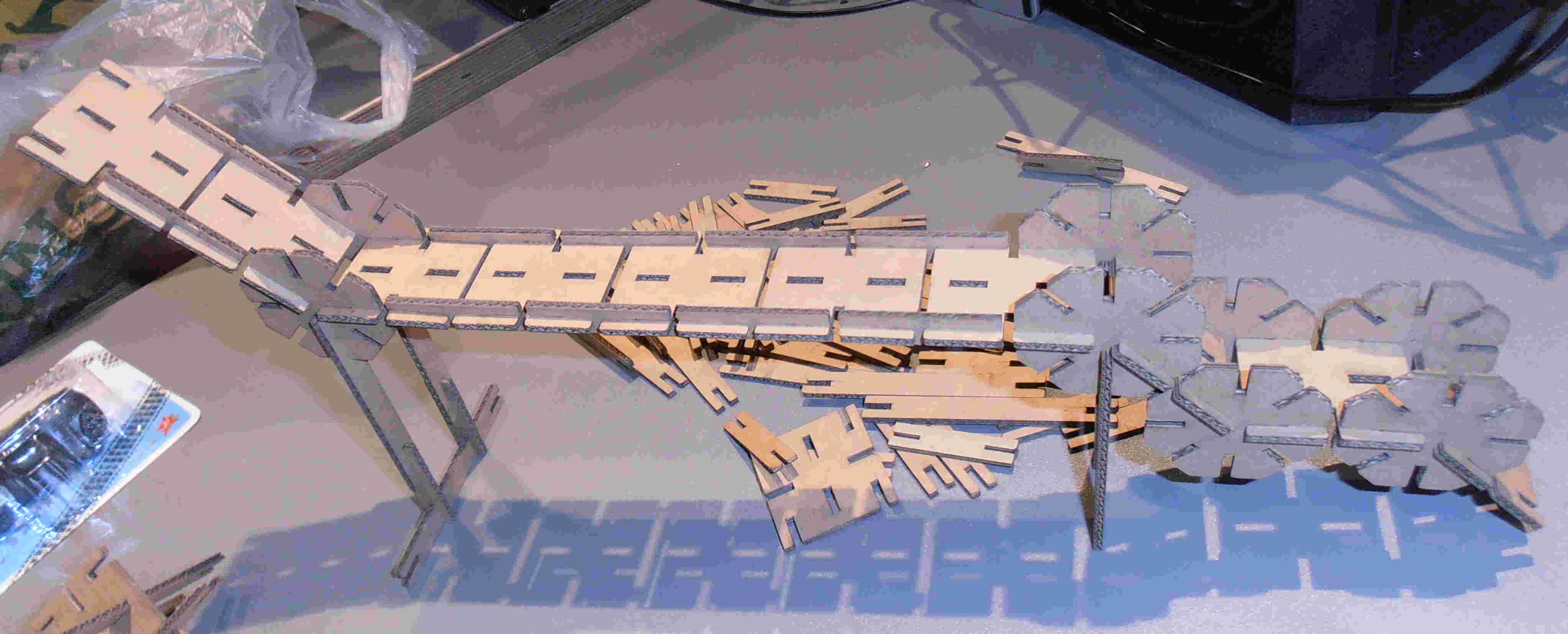
Afterwards, I manufactured larger quantities of the building blocks and
began creating tracks shapes. Due to the change in the thickness
of the card the laser power was reduced to power 70 and speed 70 to
achieve an effective cut. The thinner card was a slightly
better quality than the previous board and snapped together easier and
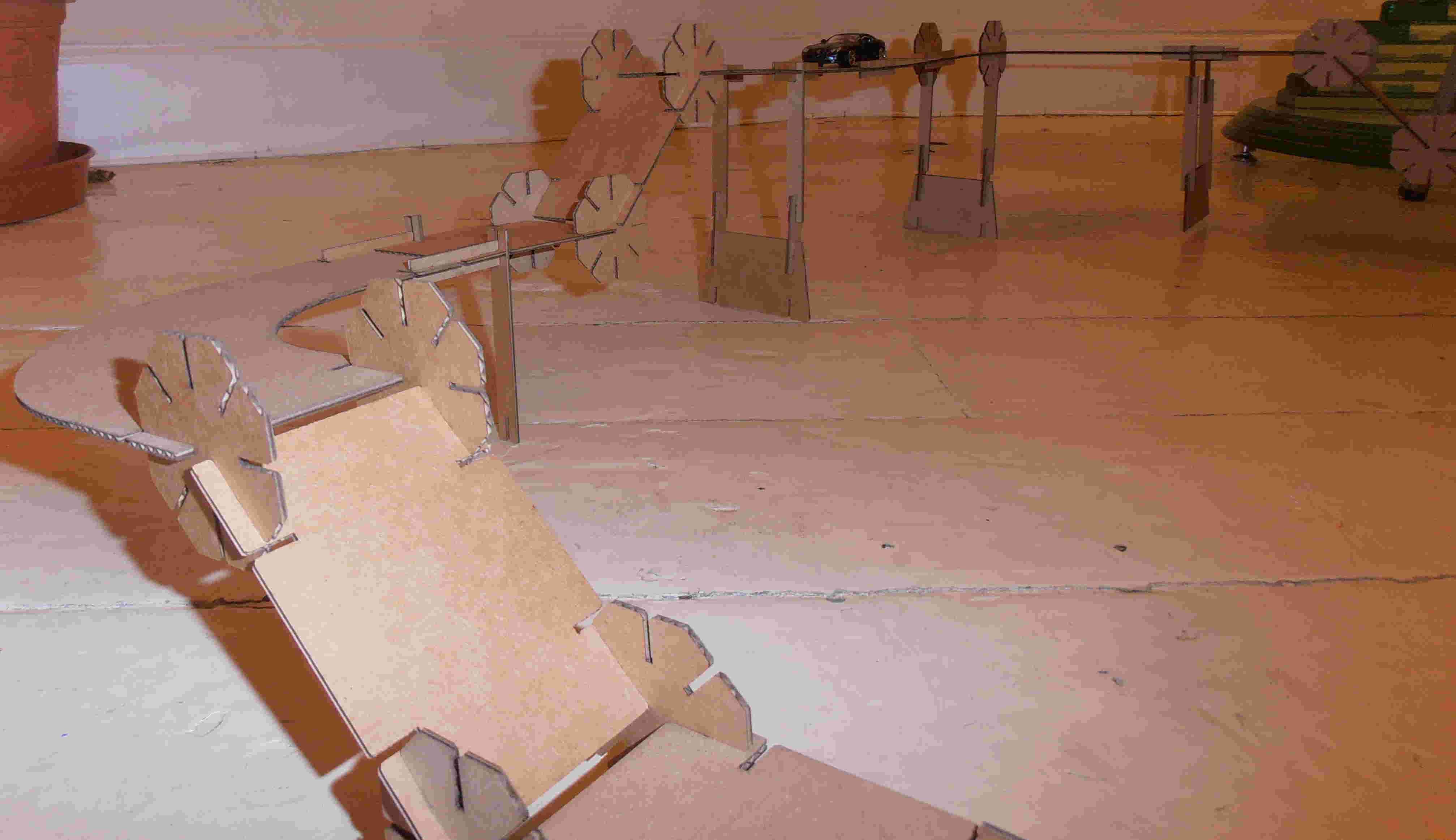
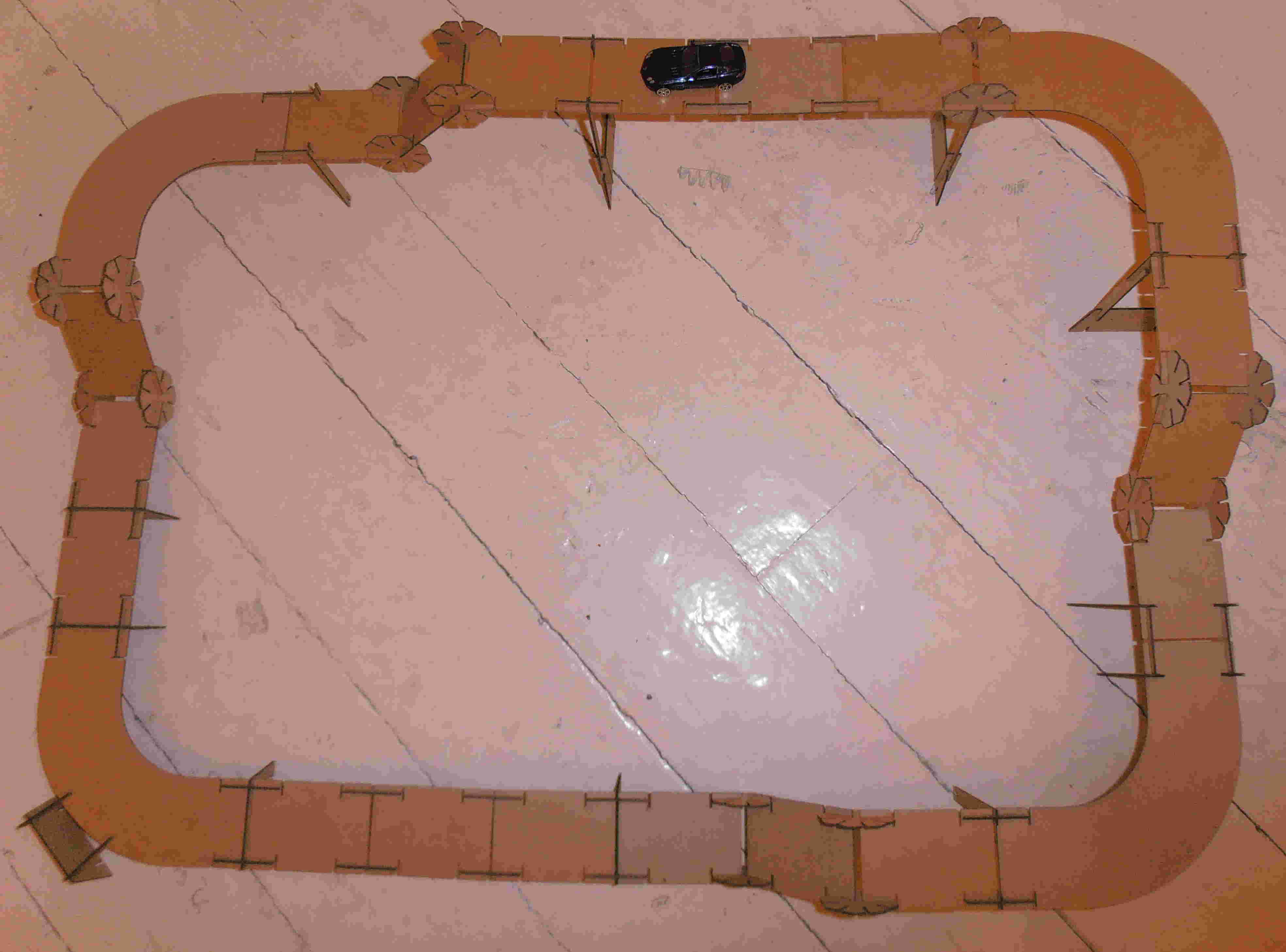
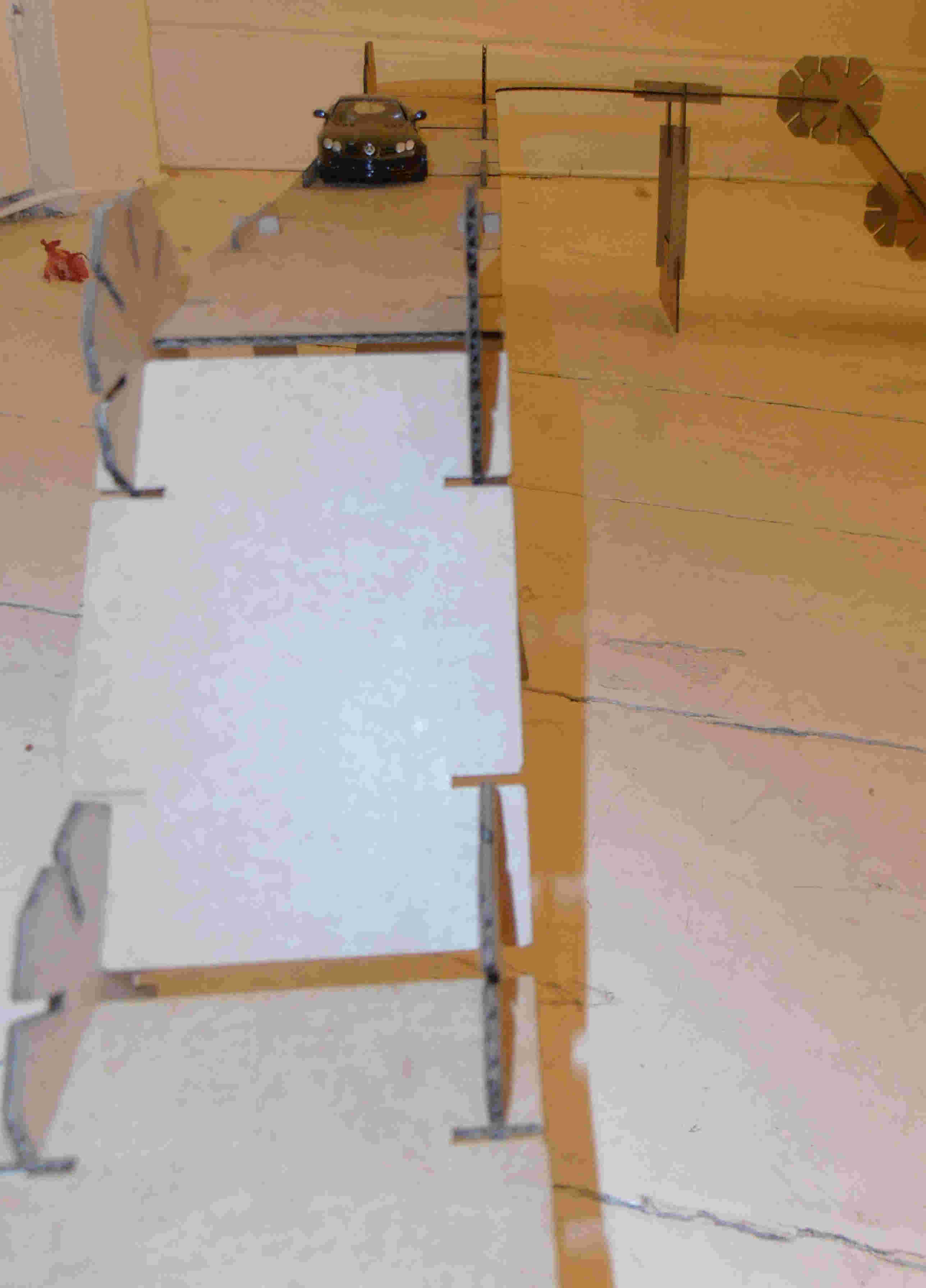
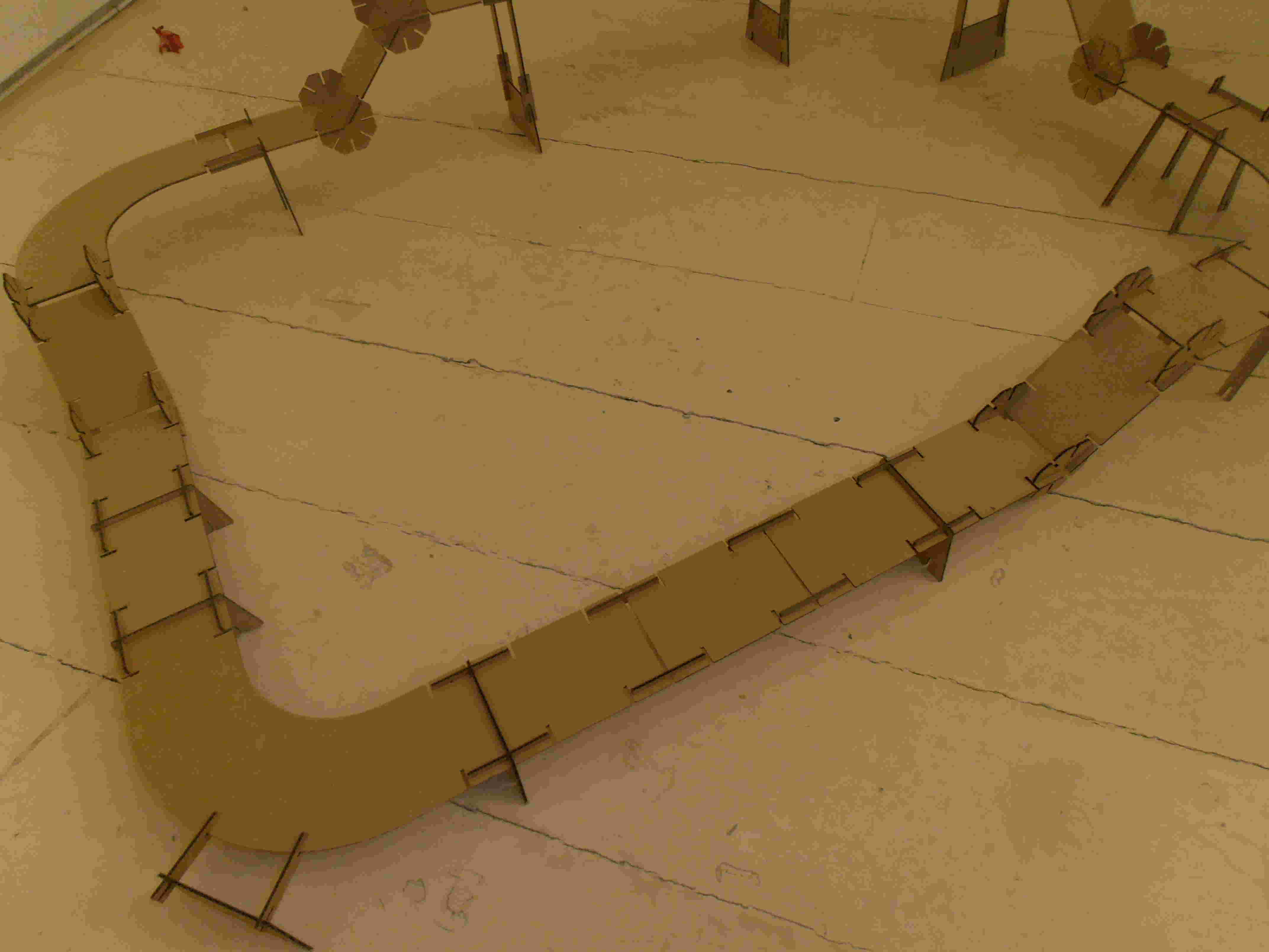
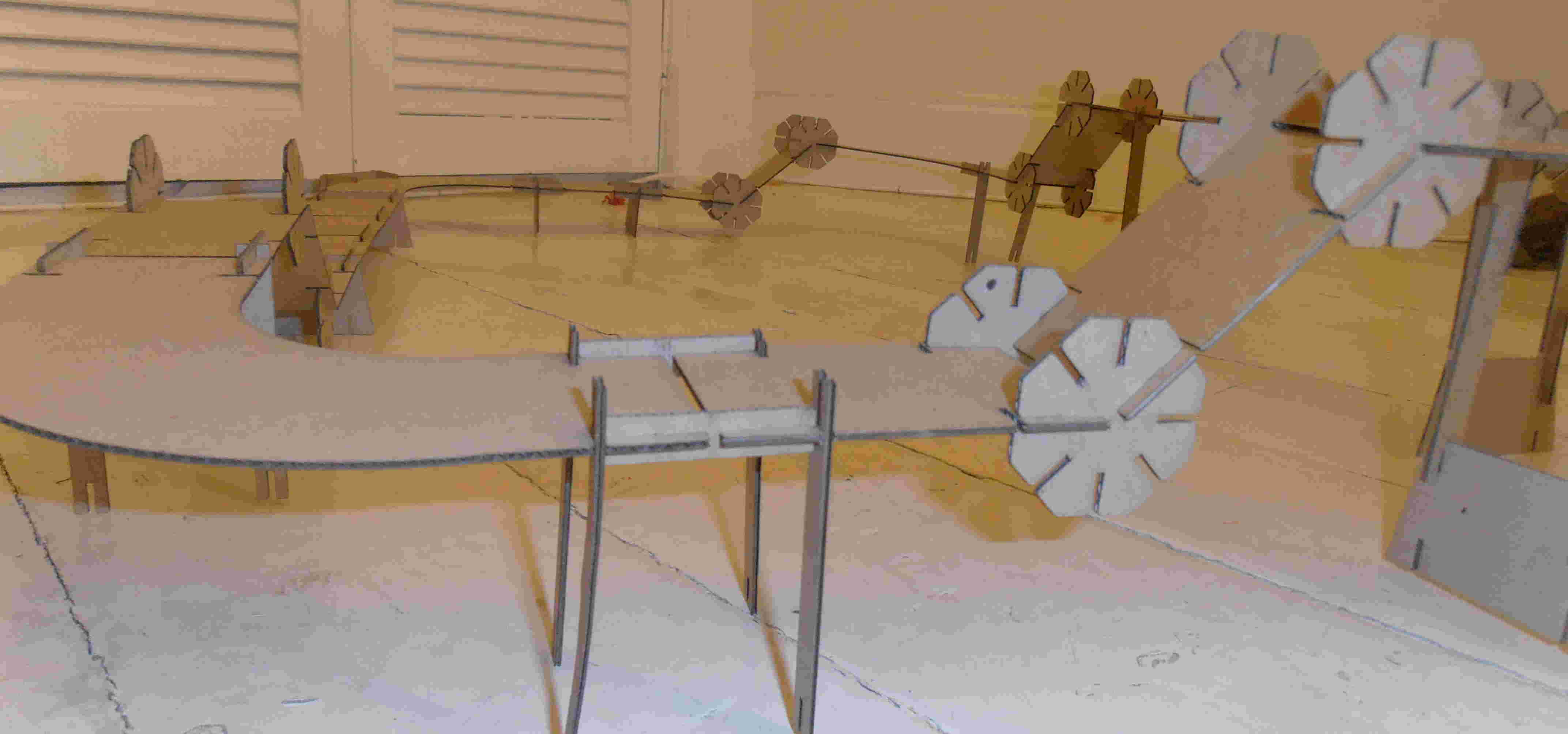
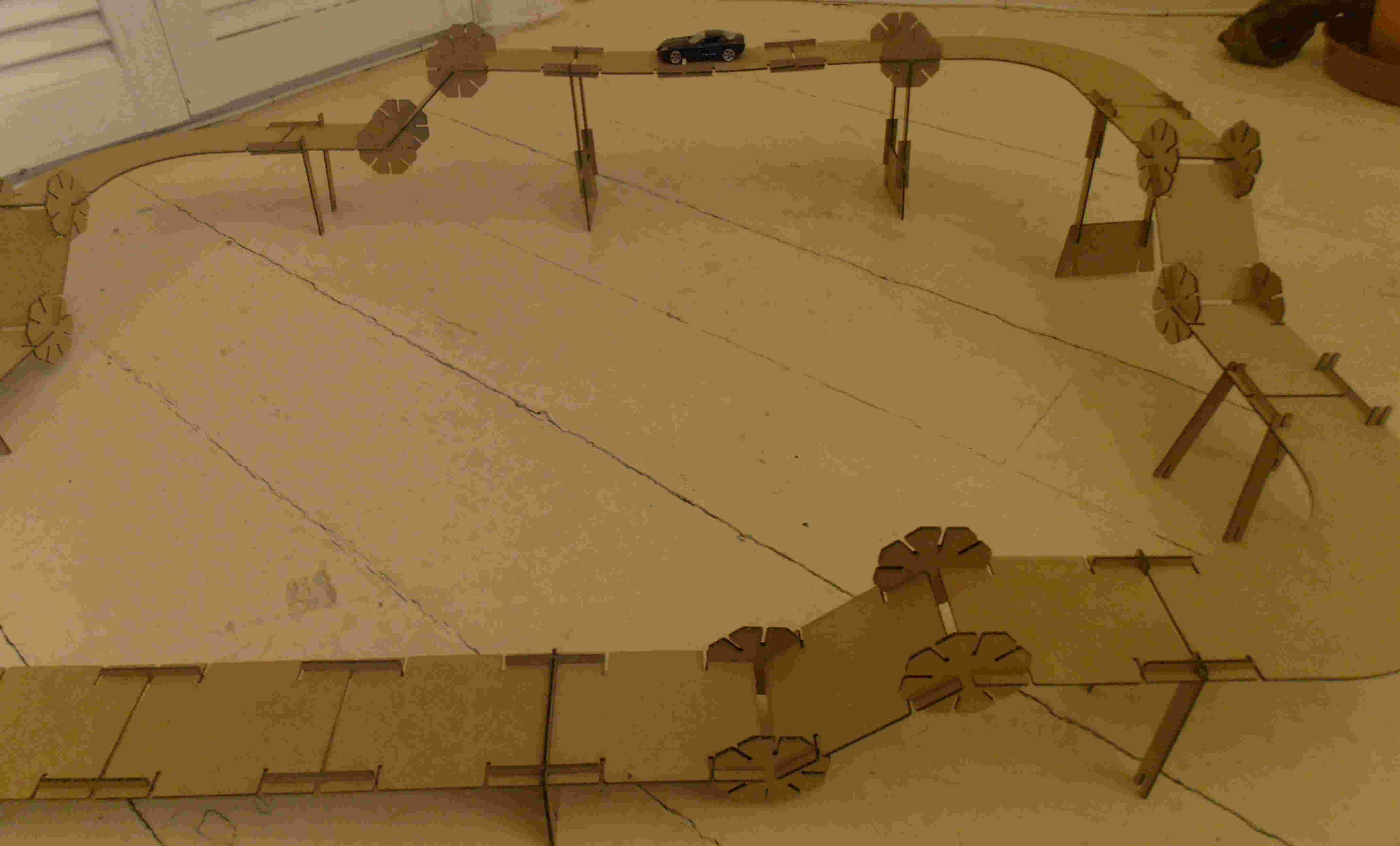
provided a nice smooth finish for the track. I constructed a
basic circular track for a matchbox car, that change it height and
direction whilst being fully supported throughout.
On the curved
sections it will be necessary to construct a barrier, which could easily
follow the edge of the curve to enable the car to be guided around the
track. This could be achieved using string or some other
additional material, but will not be achieveable in the
cardboard. Middle fixing/anchor points could have been included
to provide more rigity to the barrier, but were neglected in the
original design.
|