Final Project
Week 0: Digital Fabrication Principles and
Practices
Week 1:
Collaborative Technical Development, Documentation and Project
Management
Week 2:
Computer Aided Design
Week 3:
Computer Controlled Cutting
Week 4:
Electronics Production
Week 5:
3D Scanning and Printing
Week 6:
Electronics Design
Week 7:
Moulding and Casting
Week 8:
Embedded Programming
Week 9:
Computer Controlled Machining
Week 10:
Input Devices
Week 11:
Composites
Week 12:
Interface and Application Programming
Week 13:
Output Devices
Week 14:
Networking and Communications
Week 15:
Mechanical Design and Machine Design
Week 16:
Applications and Implications
Week 17:
Invention, Intellectual Property and Income
Week 18:
Project Development
Week 19:
Final Project Presentation
|
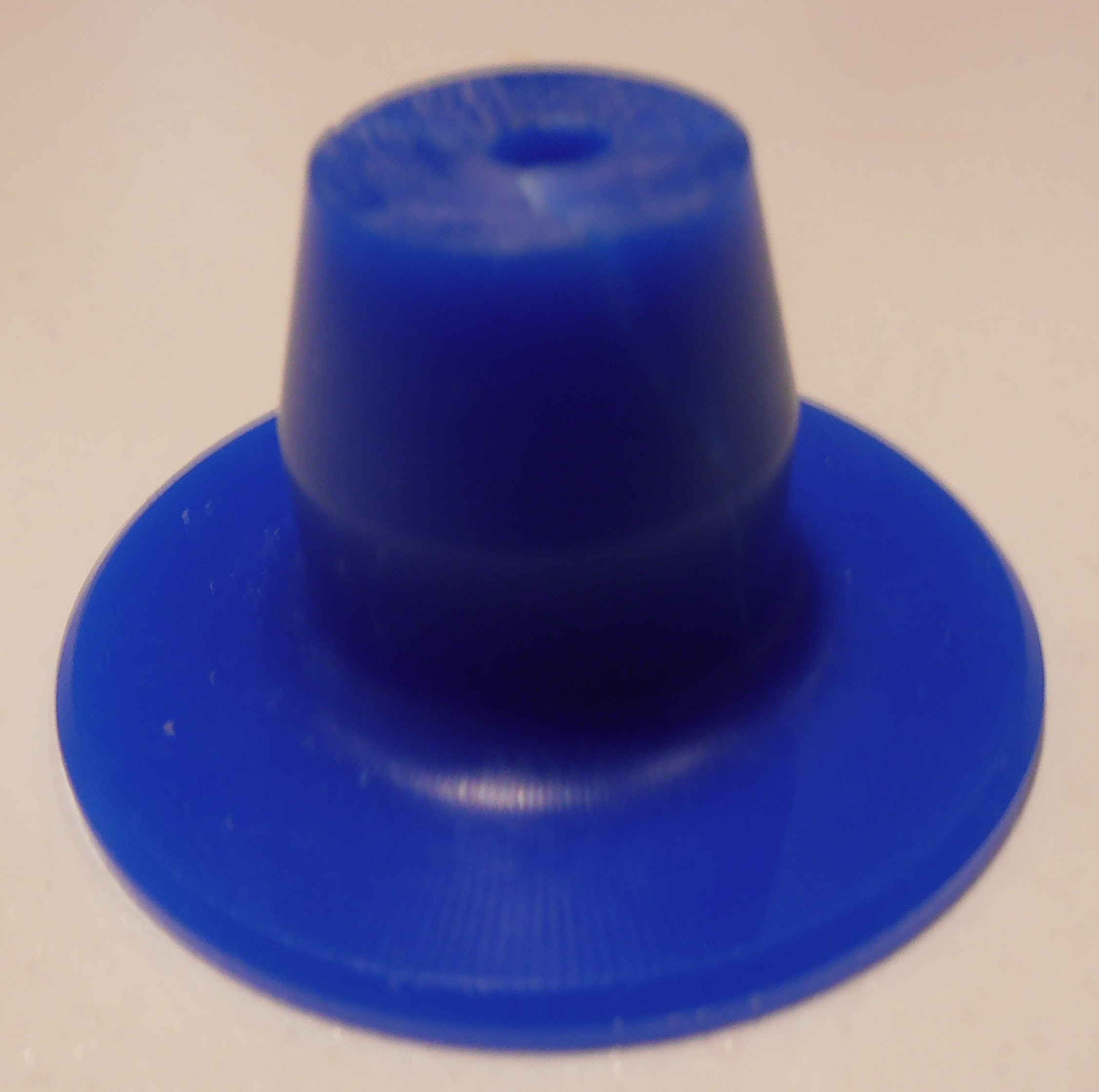
Moulding and Casting
The
assignment this week required us to mill some wax to create a positive
mould and then cast around the mould with a silicon to create a
negative mould. From this negative mould you can then remove the
wax by heating and then you are able to cast the desired object with
plaster or equivalent. The ability to create a initial positive
mould is intriguing as it allows the designer to produce the desired
final product and then eventually make exact copies of that initial
design, previously I imagined that you would have to create a negative
initially and then cast from that.
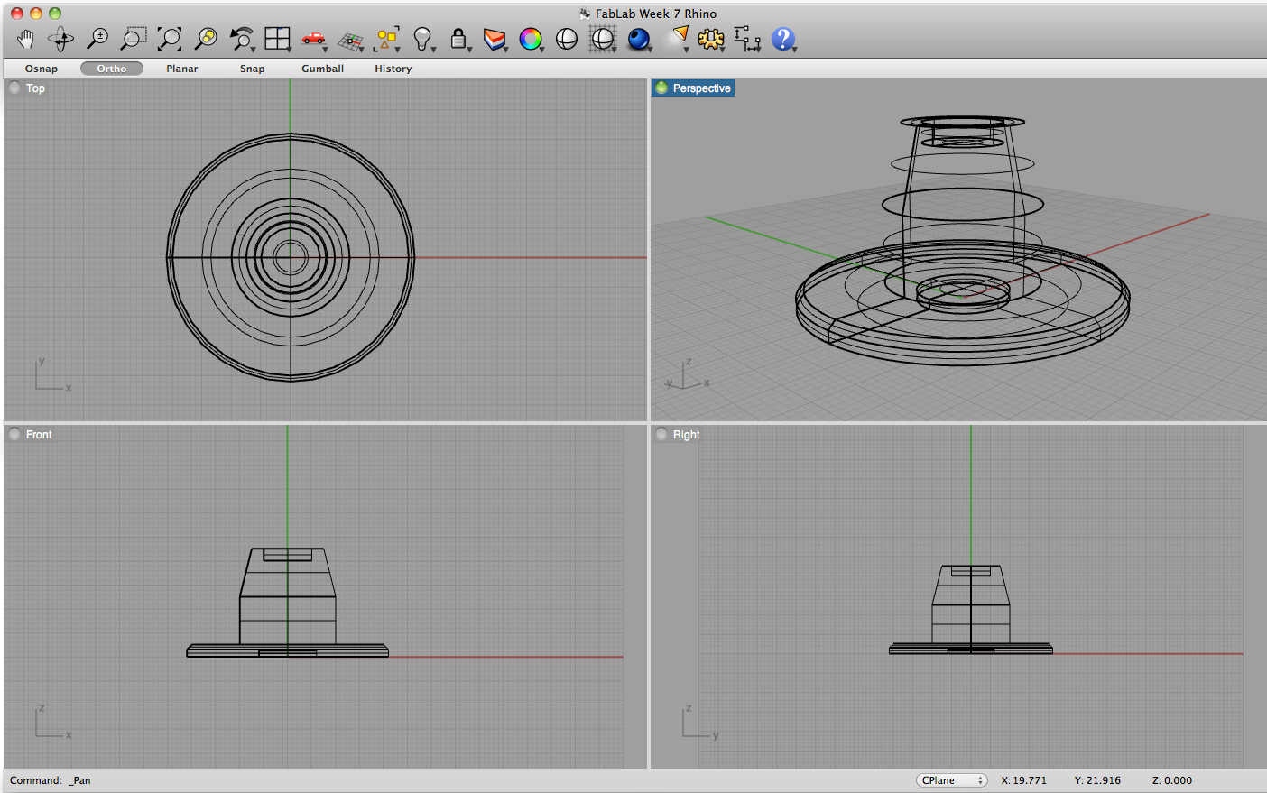
I created a 3D model in Rhino to
mill, the piece shown below is meant to become a part of a bearer
between two different types of construction material; in particular
looking at sole plate junctions at the corners of timber frames.
By exporting the file to an .stl within Rhino a mesh is created, I checked that the mesh created was whole by importing .stl into MeshLab.
Whilst designing this piece I was made acutely aware that the cutting
depth was limited by the flute and the cutting depth on the finishing
tools and was careful to ensure that my design was not greater than
25mm as these were the maximum depth of the tools available.
|
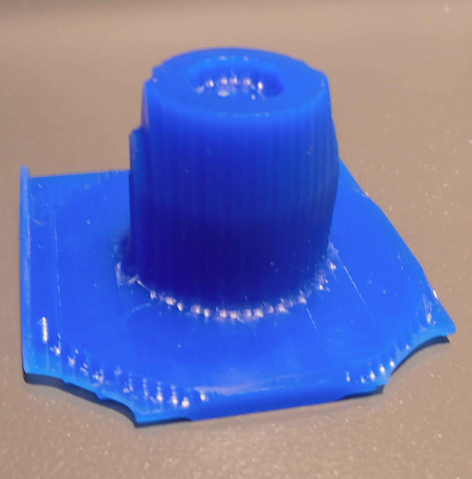
Milling:
Once this was
completed, I attempted to the mill the was on a Modela MDx-40 using a
6mm roughing tool and a 3mm finishing tool. I used a program
called Cut3D,
that allowed me to create the necessary toolpaths, this program was
very easy to use and included a step by step wizard to allow me to
achieve the desired finish. The finished piece did not have the
required finish as the step over on the finishing tool piece was too
small to achieve a smooth finish on the milled wax piece.
|
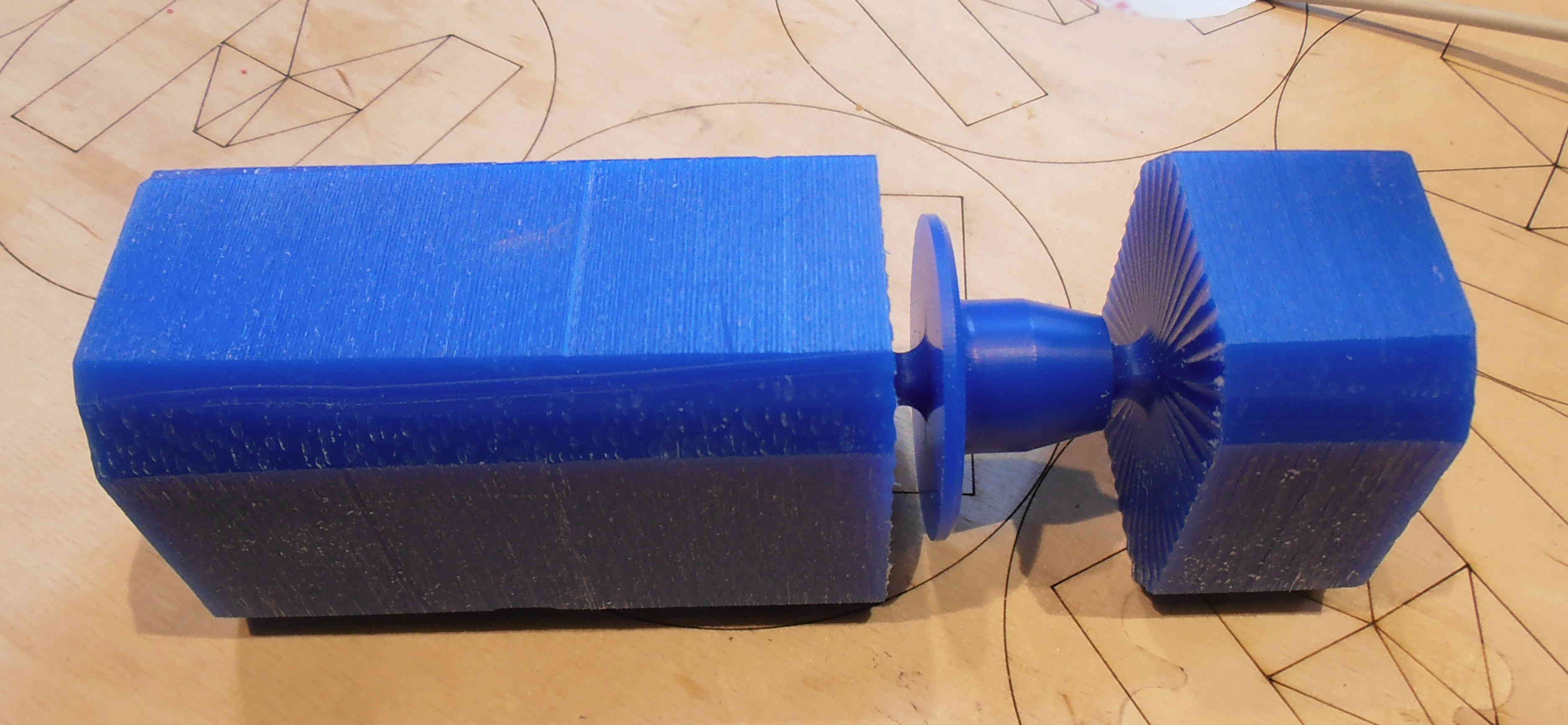
Due to the fact that my finished piece was cyclindrical, I decided for
my second attempt at creating a milled wax object I was going to use
the rotary axis unit (ZCL-40A) that could be fitted into the Roland
Modela (use the accompanying instruction manual to ensure correct
calibration) allowing the object to be turned. Using a different
program Roland SRP Player,
I imported my .stl file and went through the wizard to ensure that my
piece was milled correctly. It was important to note that the
pieces that I milled from, where not cyclindrical but rectangular, to
avoid any problems with the cutting tool I planed the corners of the
wax piece and then used the longest diagonal cross sectional length to
set the diameter of the piece within the program.
Casting Around the Mould:
This
process was fairly time consuming but gave a quality finish around the
circumference of the work piece. Once this was done, I removed
the piece from the original block using a band saw and sanded the
excess remaining part of the milling supports. I required a hole
to be set through the middle of the piece which was not feasible to be
achieved using the milling process and decided to use a pillar drill to
central hole. I started with a smaller than necessary drill bit
to ensure that the alignment was correct but unfortunately I must have
drove the drill bit into the wax too quickly as I caused a slight crack
in the piece to form. I had initally wanted to go through the
hole again with a larger drill bit diameter but decided to cut my
losses and cast the latex around the piece whilst I could.
|
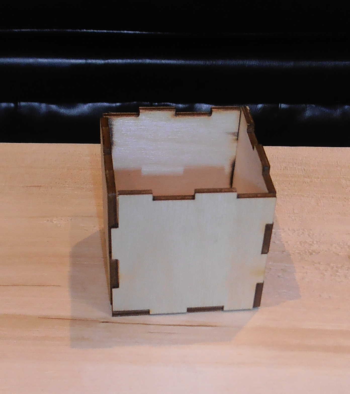
To enable this
to casting process to be successful I needed a demountable container to
pour the silicon, in around the machineable wax piece. In order
to do this I used a snap fixed ply box, created by Roy for the snap fit
construction week assignment and taped the joints to ensure that it was
fully watertight. In then placed piece base down in the box, so
the base of the box gave access to the base of the mould for ingress
and egress of the cast and the was respectively.
|
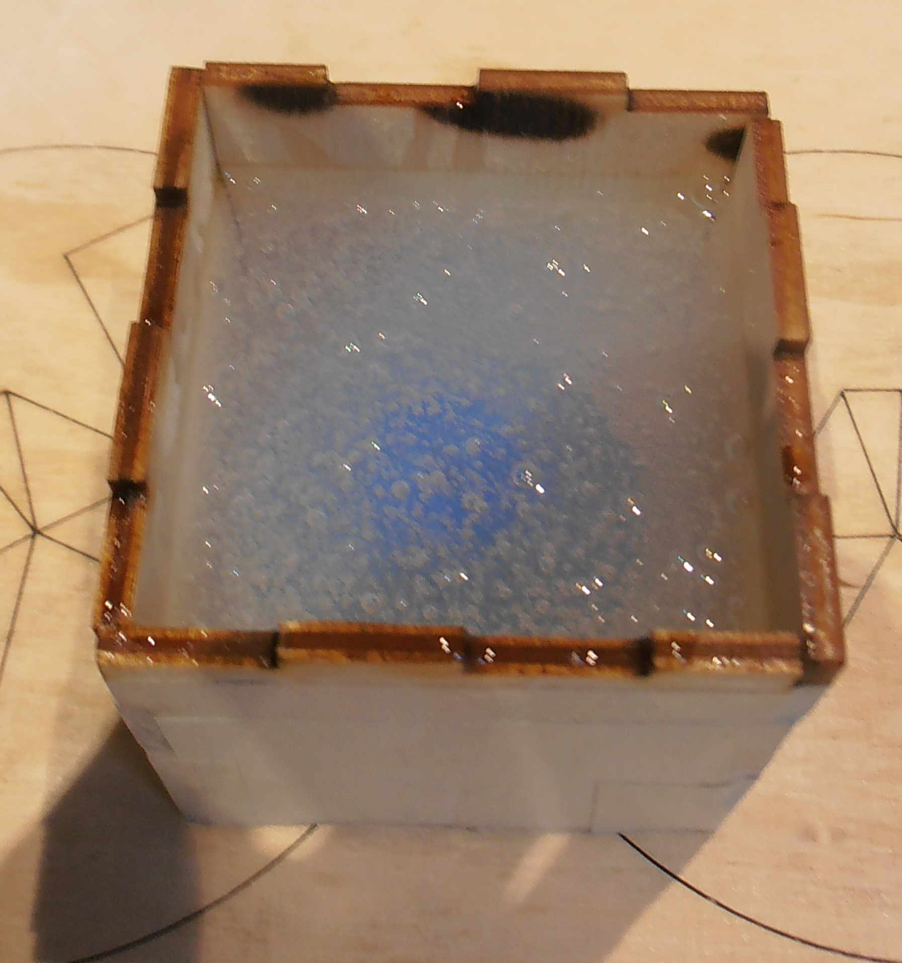
|
I then, create the silicon moulding gel by using the instructions on
the box for the portions for the silicon and the activation
liquid. The ratio here was 1:10 activator to silicon, and I
decided to measure this roughly by using spoonfuls. My advice is
to not do this as I ended up putting loads of air into my mixture which
should be limited at all costs to allow for a smooth finish to form. To
ensure that the amount of air entrapment in the silicon is limited,
when you mix the silicon material together you should try and shear the
material and consciously try not to fold in any air into the mixture
that could potentially cause bubbles to form within the silicon.
When pouring the silicon over the mould you should ensure that the
mixture is pour in from the highest point possible to try and disperse
any air within the mixture by the yield stretch pour method.
|
|
After the silicon has cured the wax can then be melted and
removed. I found that the shape of my mould and the flexibility
of the mould material allowed me to pull out the wax positive without
the need to melt the wax in the oven. The mould was full of
little air bubbles but hopefully these bubbles are within the set
silicon solid and not on the surface, only time will tell!
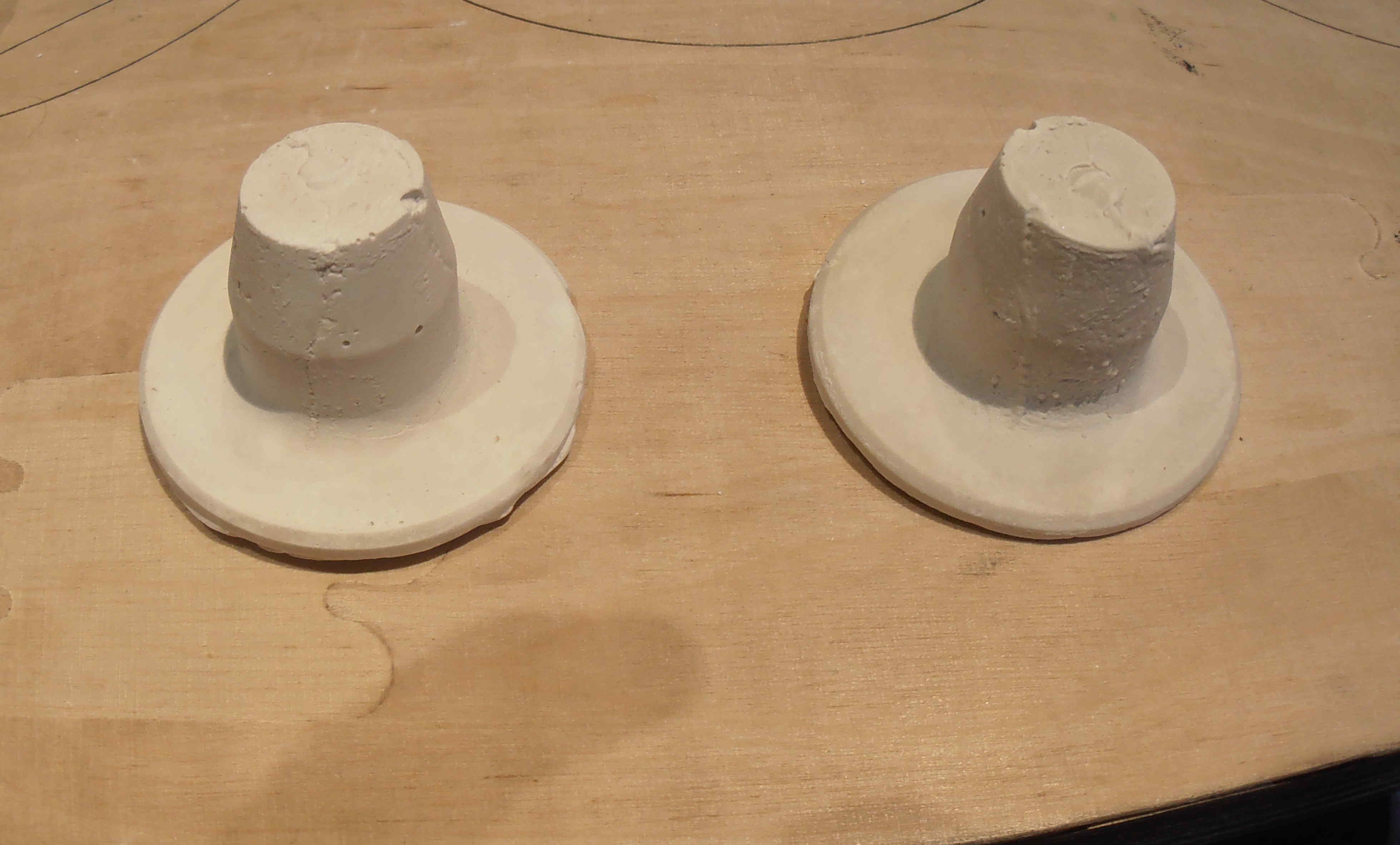
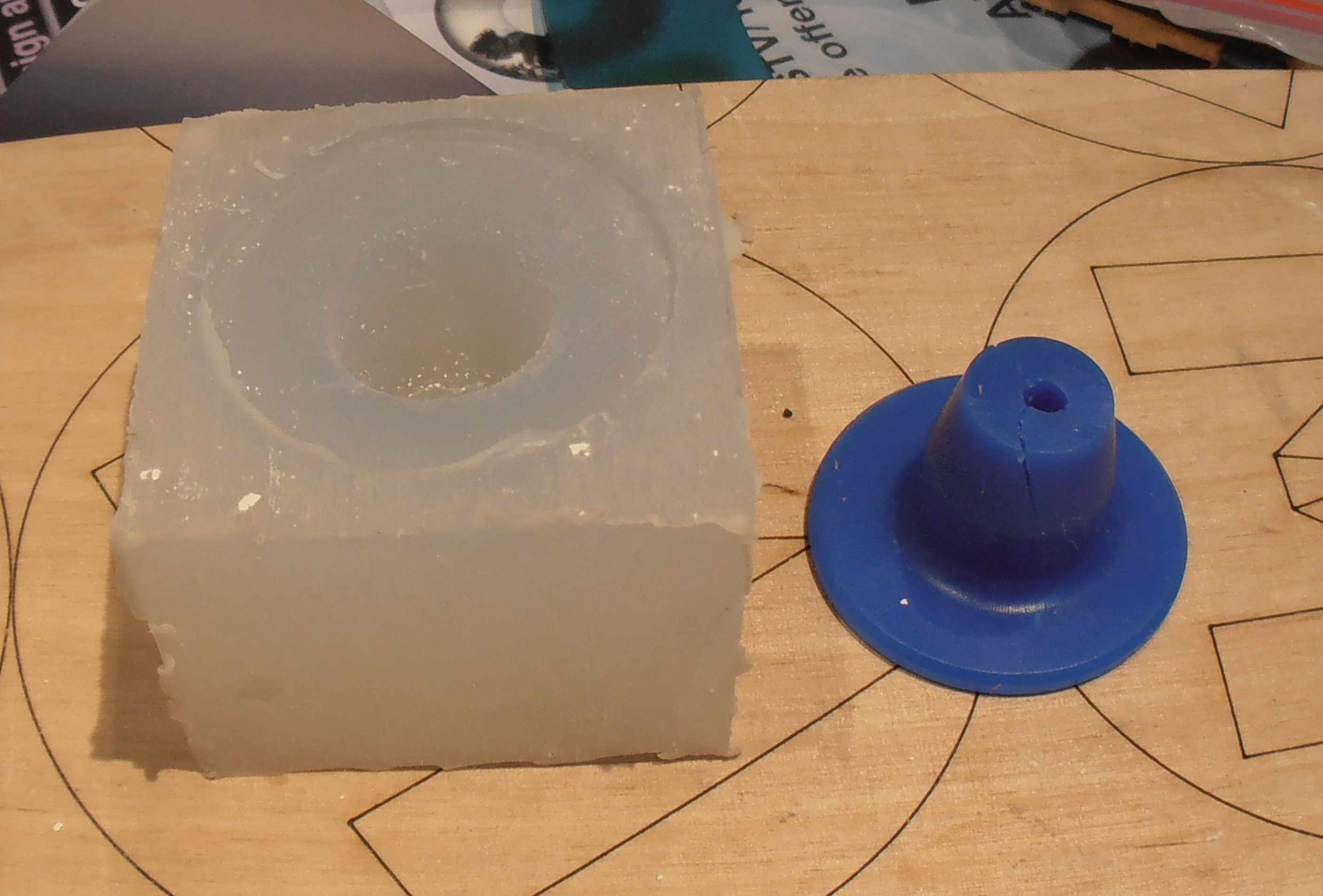
Afterwards, I decided to use a plaster based cast, to see if any of the air bubbles are on the surface of the mould.
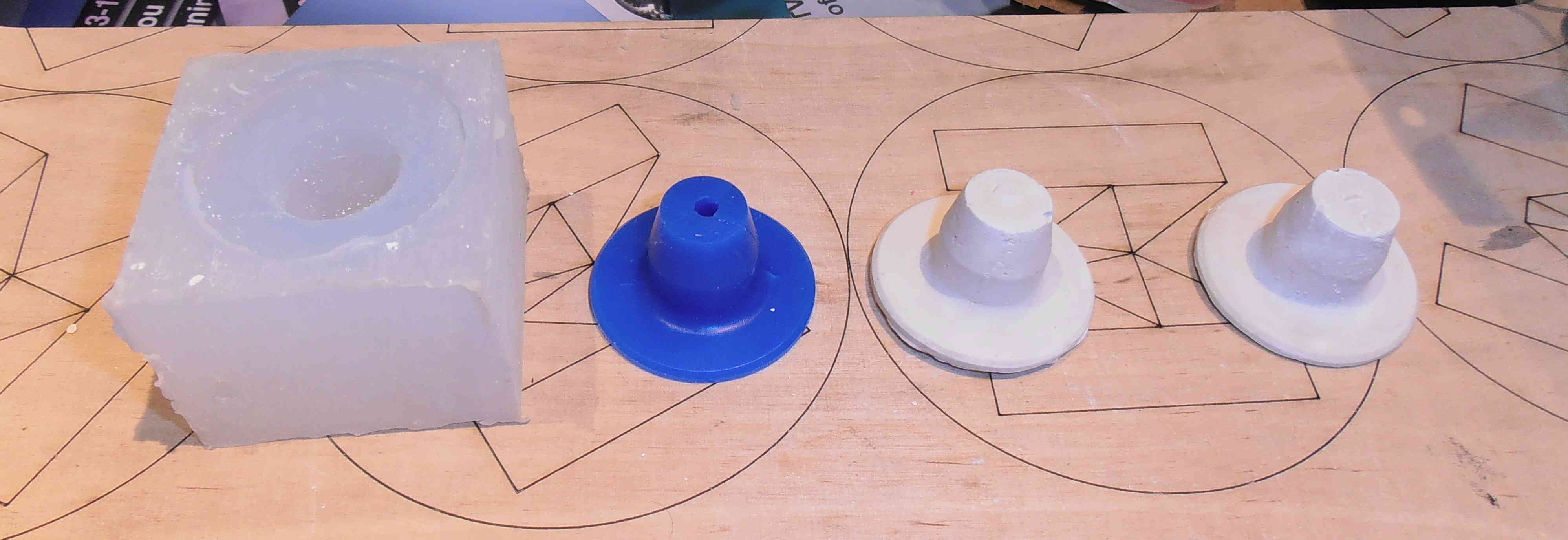 |
Using
the Hydrastone was very complicated and found this tutorial for the
setup of the process very useful except I used a 4:10 water to plaster
mix as it was stated on the outside of the packet that the Hydrastone
came in. After about 30 minutes I was able to demould the cast
easily from my flexible silicon mould, the plaster finish picked up all
the details of my primary wax mould (including the crack I caused)
there were a few air pockets/bubbles in the finished mould although I
was surprised there wasn't any more! Next time, I would
definitely, ensure that the silicon was made without as many air
bubbles as possible and make sure you trim the Hydrastone almost
immediately after it has initially cured otherwise it the material is
extremely hard and not easy to trim accurately.
|