Final Project
Week 0: Digital Fabrication Principles and
Practices
Week 1:
Collaborative Technical Development, Documentation and Project
Management
Week 2:
Computer Aided Design
Week 3:
Computer Controlled Cutting
Week 4:
Electronics Production
Week 5:
3D Scanning and Printing
Week 6:
Electronics Design
Week 7:
Moulding and Casting
Week 8:
Embedded Programming
Week 9:
Computer Controlled Machining
Week 10:
Input Devices
Week 11:
Composites
Week 12:
Interface and Application Programming
Week 13:
Output Devices
Week 14:
Networking and Communications
Week 15:
Mechanical Design and Machine Design
Week 16:
Applications and Implications
Week 17:
Invention, Intellectual Property and Income
Week 18:
Project Development
Week 19:
Final Project Presentation
|
Electronics Production
For
this
week the assignment is centered on the production of a circuit board
and the soldering of electronic components onto the circuit board to
create a FabISP in-circuit programmer. The design of the layout
of the circuit board was not necessary, merely the fabrication and the
installation of the firmware onto the in-circuit programmer was
necessary but these still posed many problems during the week.
Milling the board:
To
create the circuit board it was necessary to mill out a copper faced
rigid epoxy glass (FR4) or phenolic paper (FR1) board. It was
suggested to use FR1 board as it was kinder on the milling tools but
the immediately available board in the laboratory was the expoxy glass
board. Using the .png file supplied through the class links I
imported the file into the router software on the linked computer,
because the router being used was the Roland Modela MDX-40 and not the
specifically specified router in the Fab Lab inventory I thought it was
best to use the properitary drivers and associated software instead of
trying to implement the Fab Modules into the system. Once I had
imported the .png into the software VCarve, I ensured that it was
correct size (22.99mm x 45.21mm confirmed by the guru), and then used
the function in the program to trace the cutting vectors from the
graphical file. Afterwards, I then referenced the traces to the
graphical file provided and close any gaps in the traces using the
vector creation tools in the software, this was needed for the square
pads at the head of the circuit board.
Once the cutting vectors are imported into the program, the tool and
its path needed to be decided. It was suggested that using a 1/64
inch end mill was to be used, the parameters of the tool were uploaded
into the software and a suggested cutting depth of 0.3mm was decided to
scrape off the outer layer of copper to reveal the imported
traces. The circuit board was then, stuck down to a sacrifical
ply board underneath using double sided sticky tape and set in the bed
of the milling machine. the x,y and z axis where centered over the
centre of the PCB.
The first attempt at machining the board was conducted just to mill the outside the outline of the traces.
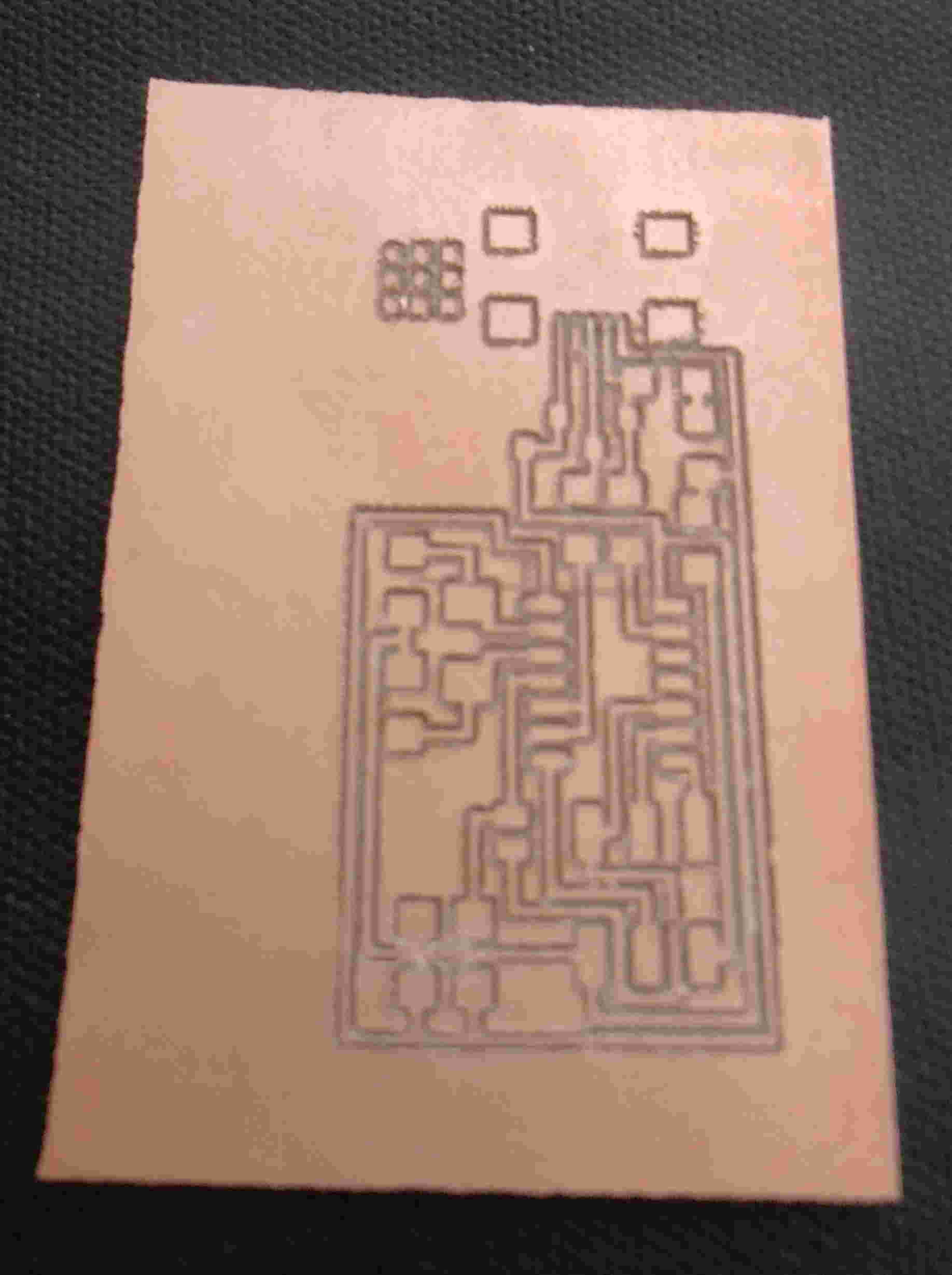
|
The outline of the traces were far too deep and caused burring of the
copper, so I decided to change the bit type to an equivalent size
engraving type piece (i.e. 0.3mm) and lower the depth of the cut to
0.1mm.
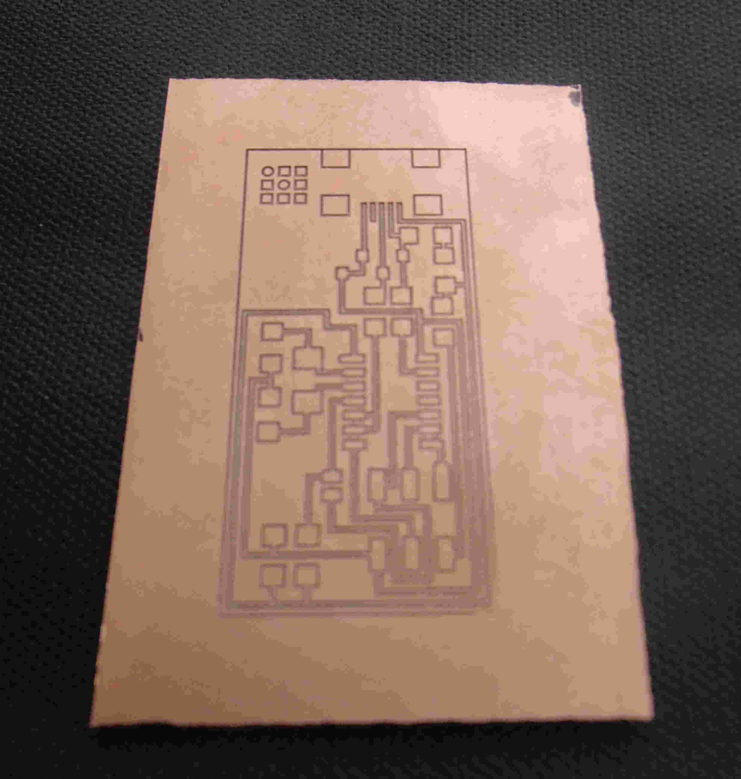
|
Here the cut was a lot neater but far to shallow, here I increased the
depth of the cut to 0.15mm and decided upon looking on the size of the
circuit to mill out all the unecessary copper to ensure no short
circuiting would occur when I soldered the components onto the
board. To mill out all the excess copper the pocket function in
the VCarve program was used to isolate the traces, using this process I
milled out the board.
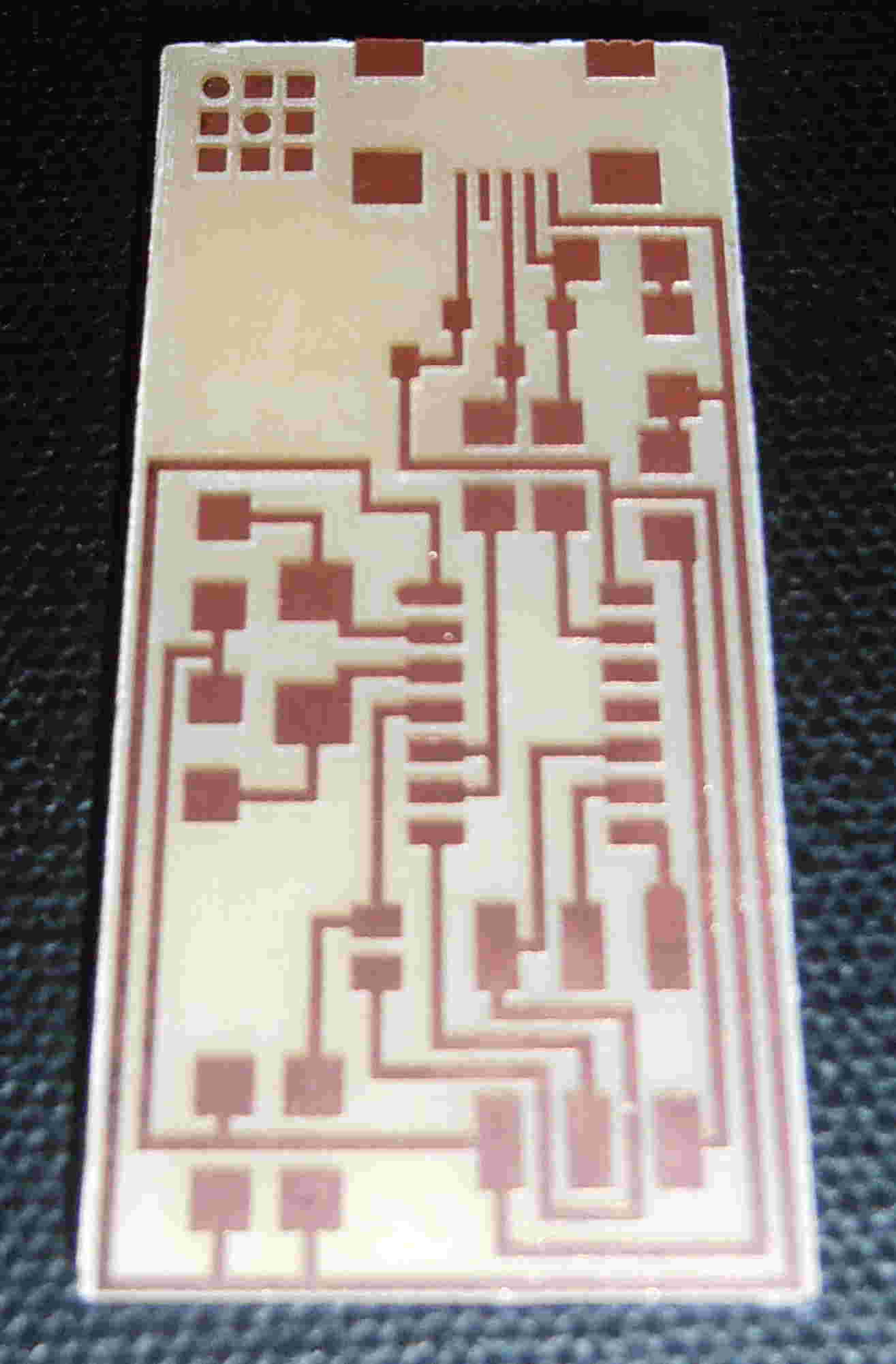
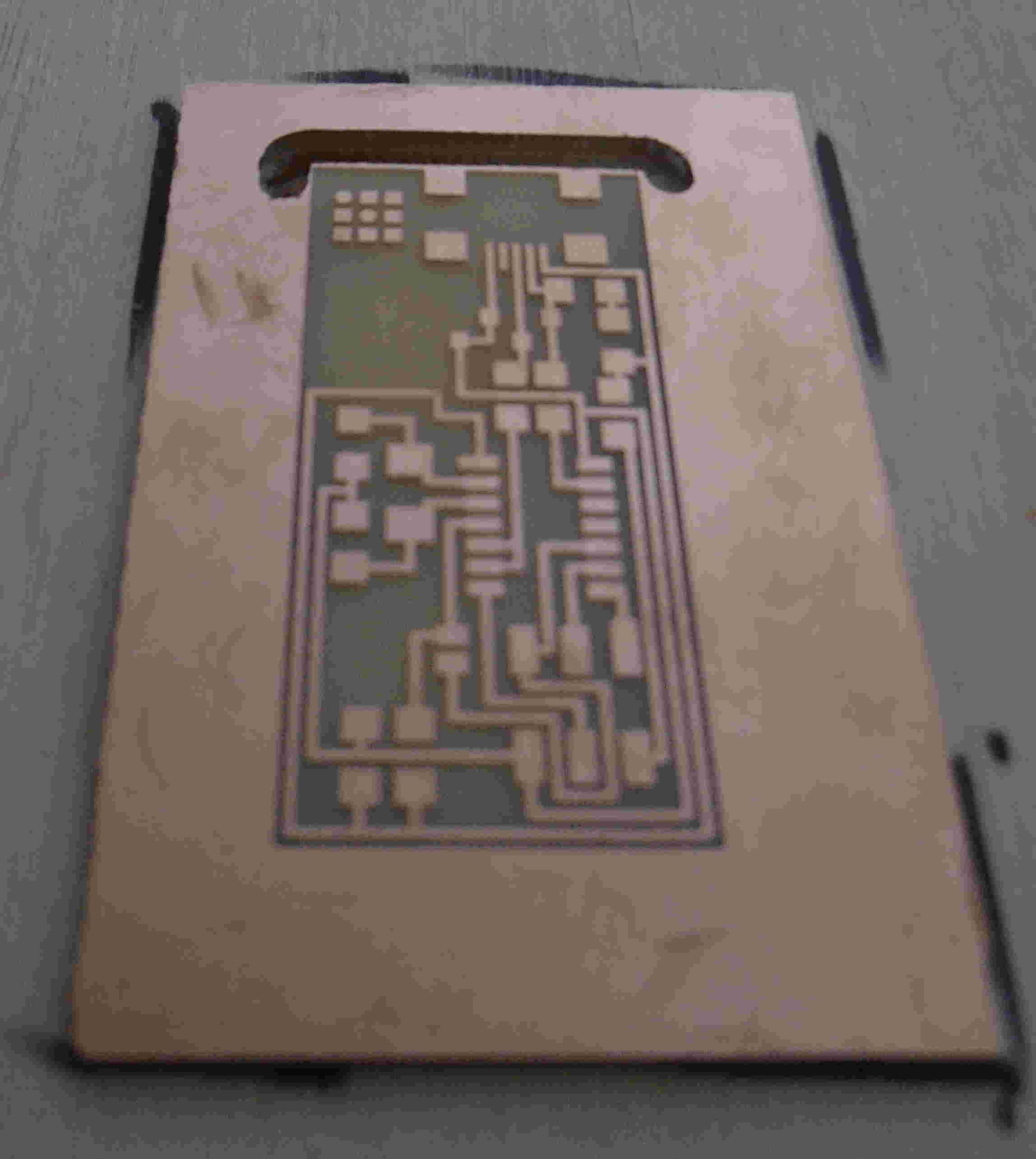 |
Here the finish was much better but far more time consuming to achieve
the milling process. Once the interior of the board was milled
effectively, the outer edge of the board needs to be cut through to
allow soldering. This was achieved by changing the mill piece to
a 0.6mm end mill, drawing an outline of cutting around the board and
setting the depth of cut to the depth of the printed circuit
board. The final mill noard ready for soldering is shown below.
|
Soldering the circuit board:
I gathered the required parts shown in the specification
in the class lecture links. Unfortunately, I had access to only
one diode and no headers and I'm waiting on a delivery of the
parts. I then arranged all remaining parts and prepared for
soldering. My preparation included obtaining a helping hand,
debraiding tape, tweezers and a clamp to restrain the circuit
board. Due to the fact that I had spare boards from the milling
procedure I practiced soldering some resistors down to a reject circuit
board and gained confidence in the process before commencing soldering
on the final board. I started soldering the components inside out
to minimise obstruction from components, firstly the chip, then the
resistors following a handy tutorial
from a previous student of the course to order the installation of the
chip. Once I had soldered all the components available, I had to
stop and await the delivery of the necessary to finish the soldering
and programming the ISP.
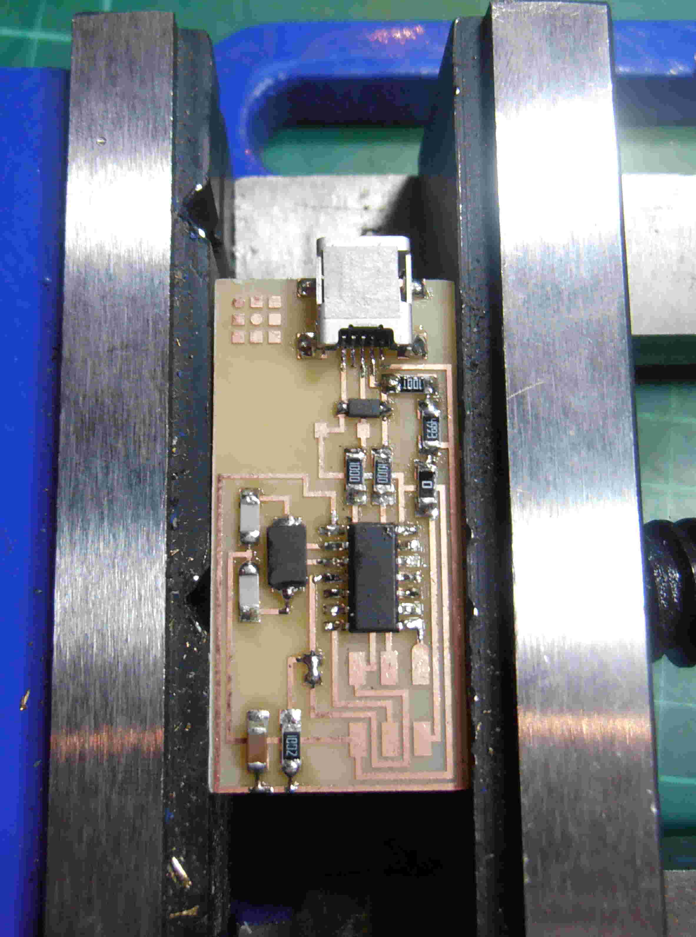
This image shows how far I got to completing the ISP this week and with
a little luck should be updated within the next week when I have
finished off the soldering and the programming.
|
Finally
managed to get the board soldered. The ordered diodes proved to
be the wrong type of diode (one with 3 securing pins), fortunately
there was several 4.7v Zener diodes on hand. Using the same
orientation (i.e. the line indicates the cathode), I soldered on the
final component onto the board. I was able to do this as the
diodes provide a voltage regulator for the USB connector but is rather
archaic as the USB drivers are fairly stable and therefore a 3.3V regulator is not really necessary.
Programming the circuit board:
Before
I could commence programming my FabISP I had to configure my computer
to allow me to do this. Firstly, I had to redirect direct the
path directories within my computer so that when I installed the
required CrossPack program the computer would look for it in the
correct directory. Using Mac OS 10.6.8 I opened terminal and had
to navigate to the root directory, this is achieved by using the
command cd.. comannd to go back to the root directory and then
following the tutorial linked here.
Following the tutorial in
the content section of the Fab Academy website, i downloaded the
firmware and followed the steps but got the below error message when I
inputted the 'make hex' command.
Thomas-Bells-MacBook-Pro:firmware thomasbell$ make hex
avr-gcc -Wall -Os
-DF_CPU=20000000 -Iusbdrv -I. -DDEBUG_LEVEL=0
-mmcu=attiny44 -c usbdrv/usbdrv.c -o usbdrv/usbdrv.o
In file included from usbdrv/usbdrv.c:12:0:
usbdrv/usbdrv.h:455:6:
error: variable 'usbDescriptorDevice' must be const in order to be put
into read-only section by means of '__attribute__((progmem))'
usbdrv/usbdrv.h:461:6:
error: variable 'usbDescriptorConfiguration' must be const in order to
be put into read-only section by means of '__attribute__((progmem))'
usbdrv/usbdrv.h:467:6:
error: variable 'usbDescriptorHidReport' must be const in order to be
put into read-only section by means of '__attribute__((progmem))'
usbdrv/usbdrv.h:473:6:
error: variable 'usbDescriptorString0' must be const in order to be put
into read-only section by means of '__attribute__((progmem))'
usbdrv/usbdrv.h:479:5:
error: variable 'usbDescriptorStringVendor' must be const in order to
be put into read-only section by means of '__attribute__((progmem))'
usbdrv/usbdrv.h:485:5:
error: variable 'usbDescriptorStringDevice' must be const in order to
be put into read-only section by means of '__attribute__((progmem))'
usbdrv/usbdrv.h:491:5:
error: variable 'usbDescriptorStringSerialNumber' must be const in
order to be put into read-only section by means of
'__attribute__((progmem))'
usbdrv/usbdrv.c:70:14:
error: variable 'usbDescriptorString0' must be const in order to be put
into read-only section by means of '__attribute__((progmem))'
usbdrv/usbdrv.c:89:14:
error: variable 'usbDescriptorStringDevice' must be const in order to
be put into read-only section by means of '__attribute__((progmem))'
usbdrv/usbdrv.c:111:14:
error: variable 'usbDescriptorDevice' must be const in order to be put
into read-only section by means of '__attribute__((progmem))'
usbdrv/usbdrv.c:142:14:
error: variable 'usbDescriptorConfiguration' must be const in order to
be put into read-only section by means of '__attribute__((progmem))'
make: *** [usbdrv/usbdrv.o] Error 1
Thomas-Bells-MacBook-Pro:firmware thomasbell$
After discussion with the guru, it was discovered that this was a
probably with the firmware that we downloaded and some elements of the
CrossPack AVR code had been altered causing the original firmware to be
non-compliant. Using this new firmware, the hex command and all
the other necessary commands worked first time, note you should be in
the firmware folder within terminal to ensure that the commands
work! The programming of my FabISP worked first time (once I had
put the header cable on the right way) and I decided just to remove the
solder bridge and not the 0 ohm resistor as it will allow me to program
subsequent boards without any additional power to the other ISP's when
they are being programmed.
|