Final Project
Week 0: Digital Fabrication Principles and
Practices
Week 1:
Collaborative Technical Development, Documentation and Project
Management
Week 2:
Computer Aided Design
Week 3:
Computer Controlled Cutting
Week 4:
Electronics Production
Week 5:
3D Scanning and Printing
Week 6:
Electronics Design
Week 7:
Moulding and Casting
Week 8:
Embedded Programming
Week 9:
Computer Controlled Machining
Week 10:
Input Devices
Week 11:
Composites
Week 12:
Interface and Application Programming
Week 13:
Output Devices
Week 14:
Networking and Communications
Week 15:
Mechanical Design and Machine Design
Week 16:
Applications and Implications
Week 17:
Invention, Intellectual Property and Income
Week 18:
Project Development
Week 19:
Final Project Presentation
|
Invention, Intellectual Property and Income
This
week mainly consisted of developing the circuit for my final
project. The idea here was to create an amalgamation of several
different input sensors and the implementation of an output via a
wireless network.
Electronic Design:
Initially
I looked into using a resistance approach at defining the moisture
content in a material, but was shown in class tutorial that the
transmit receive method was the best and simplest way of obtaining a
moisture content. Whereby the circuit will send a voltage across
the material and will measure the amount of voltage it receives,
thereby through a process of calibration will determine the moisture
content within the timber. An initial problem is that different
species of timber have different levels of natural conductivity, so
through the calibration and input you would have to include for several
different species for the product to be useful in practice To do
a calibration for many different types of trees is beyond the remit of
this project and I will calibrate the sensor for Sitka Spruce,
additional species could be added in at a later date through the
interface program.
I began understanding the layouts for the transmit and receive and the
temperature board. The inclusion of the temperature board was
decided because it would potentially give you a more accurate reading
of the moisture content if the temperature is known. Furthermore,
I wanted to include a mobile power source and a wireless sender so the device could be truly portable and could be placed in hard to reach places.
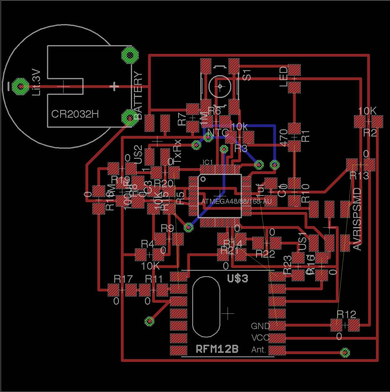
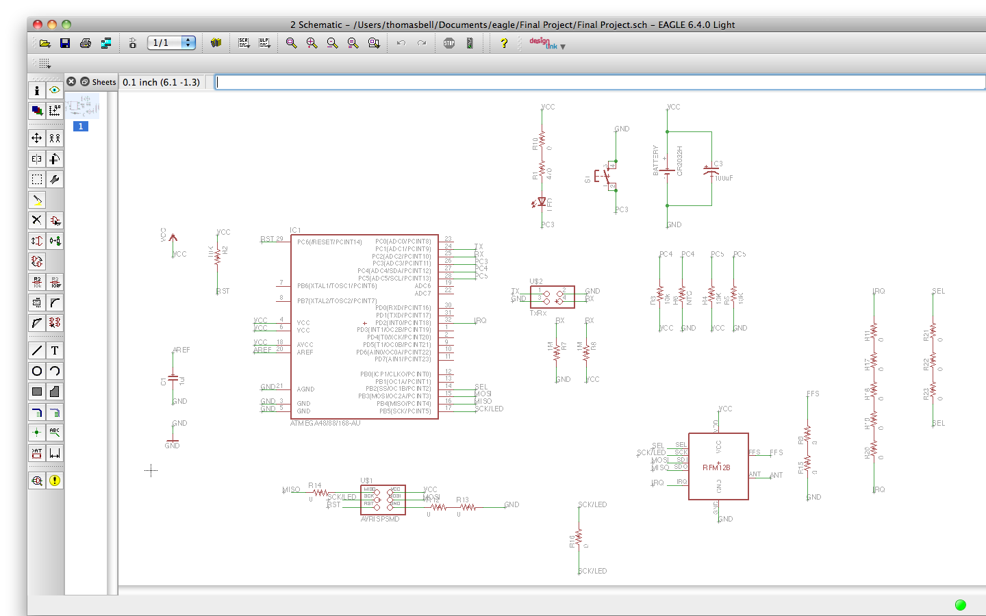
Due to the fact that I am to include, an additional sensor and a
wireless transmitter I thought it was necessary to develop my circuit
using the ATMega 328 chip. Once I had decided on the components
(particular the RF element outside the Fab Lab inventory) and the
techniques of measurement I began working up the schematic of my board
using Eagle.
You should be careful to import the correct libraries from any products
that aren't within the existing Fab Lab libraries, for the RF component I used this Library. It was important to check the datasheets for the chip and the RF component to make sure they were compatible, moreover I sieved through the sensor C files to ensure that the ports were going to the correct ports on the chip.
|
Afterwards, I began working out the board layout. Obviously the
smaller the better for the board layouts, but I was aware that the time
in creating a board would take a fair amount of time and could inhibit
further development of my time. Therefore I decided on a size of
a circuit that would be suitable for a first prototype and began
designing the circuit into these parameters.
For future
debugging, particularly when using the RF component it was necessary to
obtain a serial output to ensure that the embedded programming was
correct. To keep the circuit size to the original sizes I
specified I decided to create a FTDI header to four pin break out
adaptor to debug the circuit before putting in the RF section of the
circuit. Hopefully I will get the boards milled and stuffed at
the earliest opportunity so I can begin what I perceive as the hardest
most time consuming part of the build, embedded programming and
interfacing with the computer.
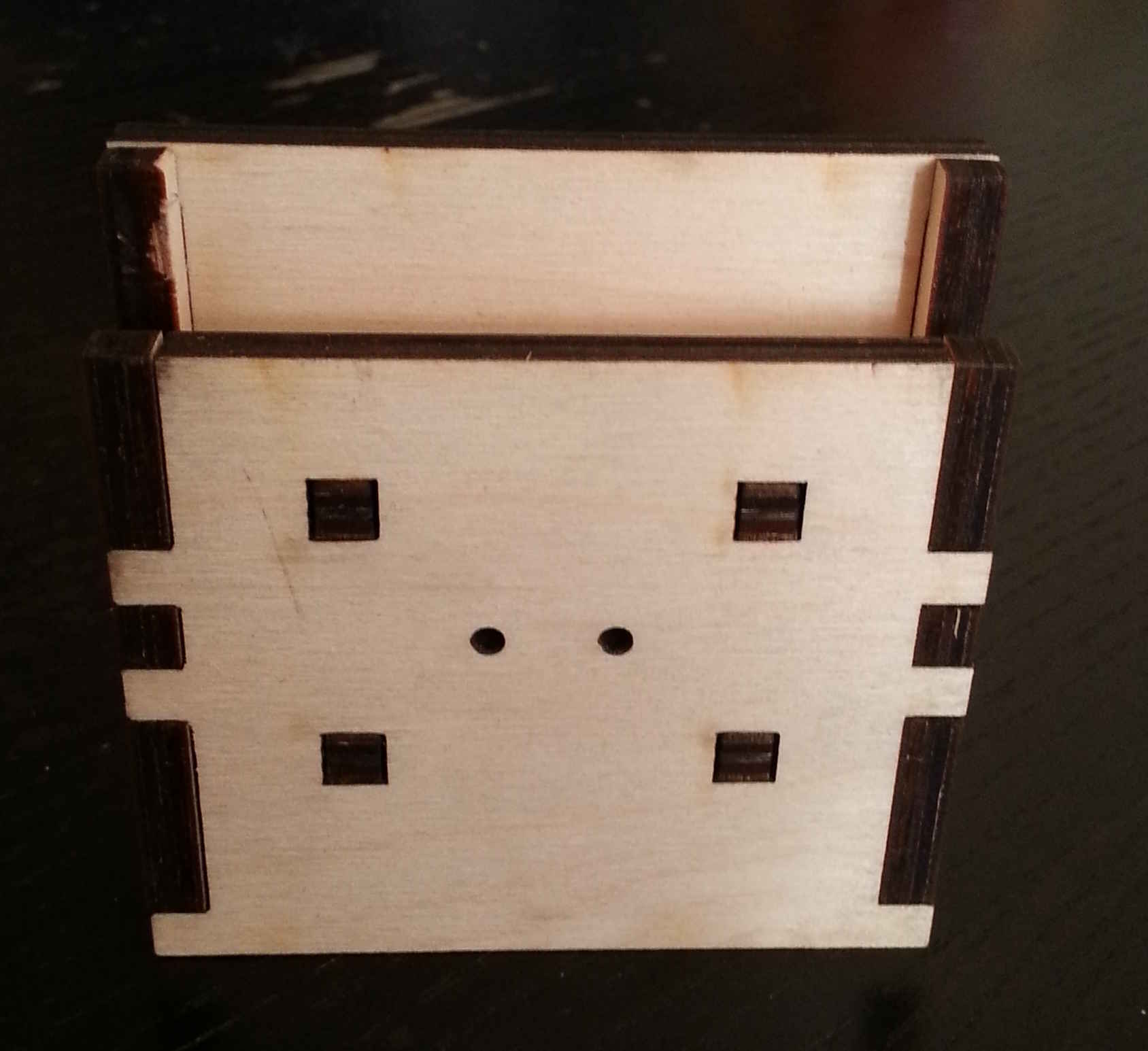
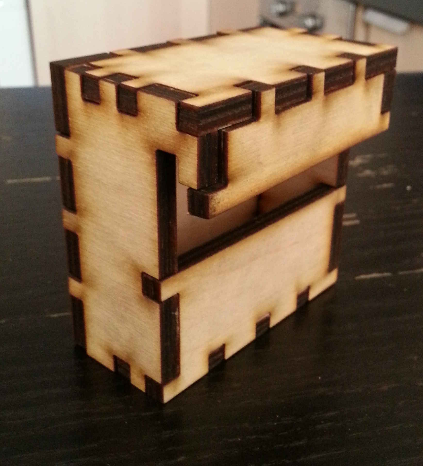
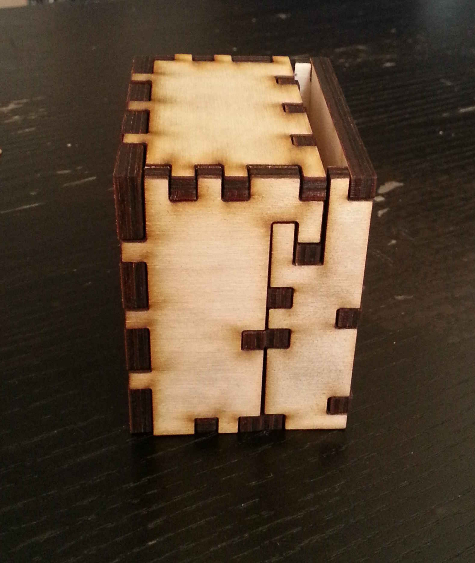
Case Design:
Using
the preset dimensions I began developing an idea for the case. I
was keen to provide a useful method of fixing the moisture sensor to
the timber. Typically the sensor needs to be driven into the
timber by approximately 20mm or so, usually achieved by a hammer
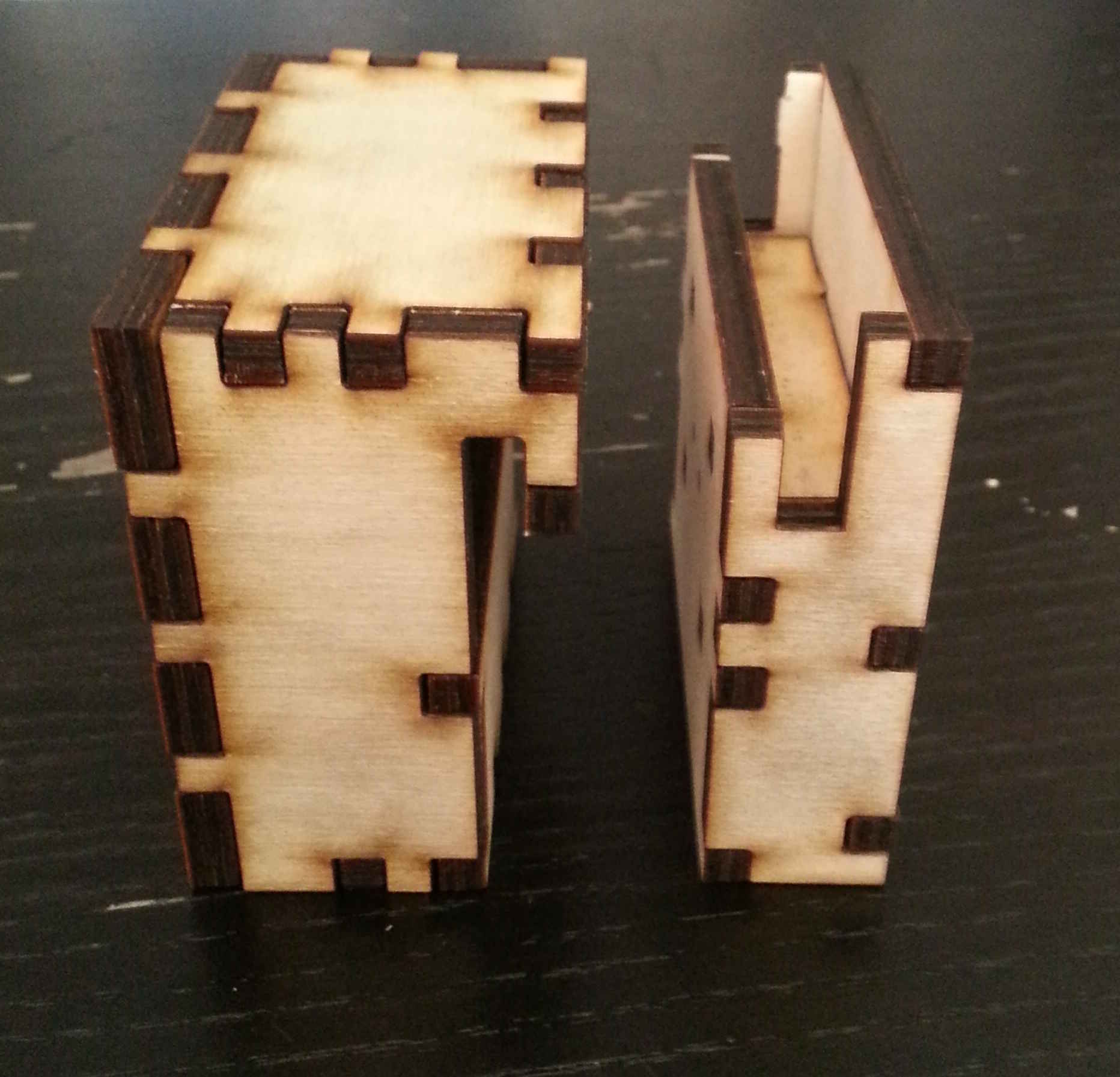
arrangement or by brute force. To not destroy the electronic
components, I decided to split the moisture sensor components as a
separate element that could be installed and then the electronic
component fixed/clipped to the moisture sensors. I hope the
mounting of the sensors will allow for easy removal of the sensor
embedded into the timber.
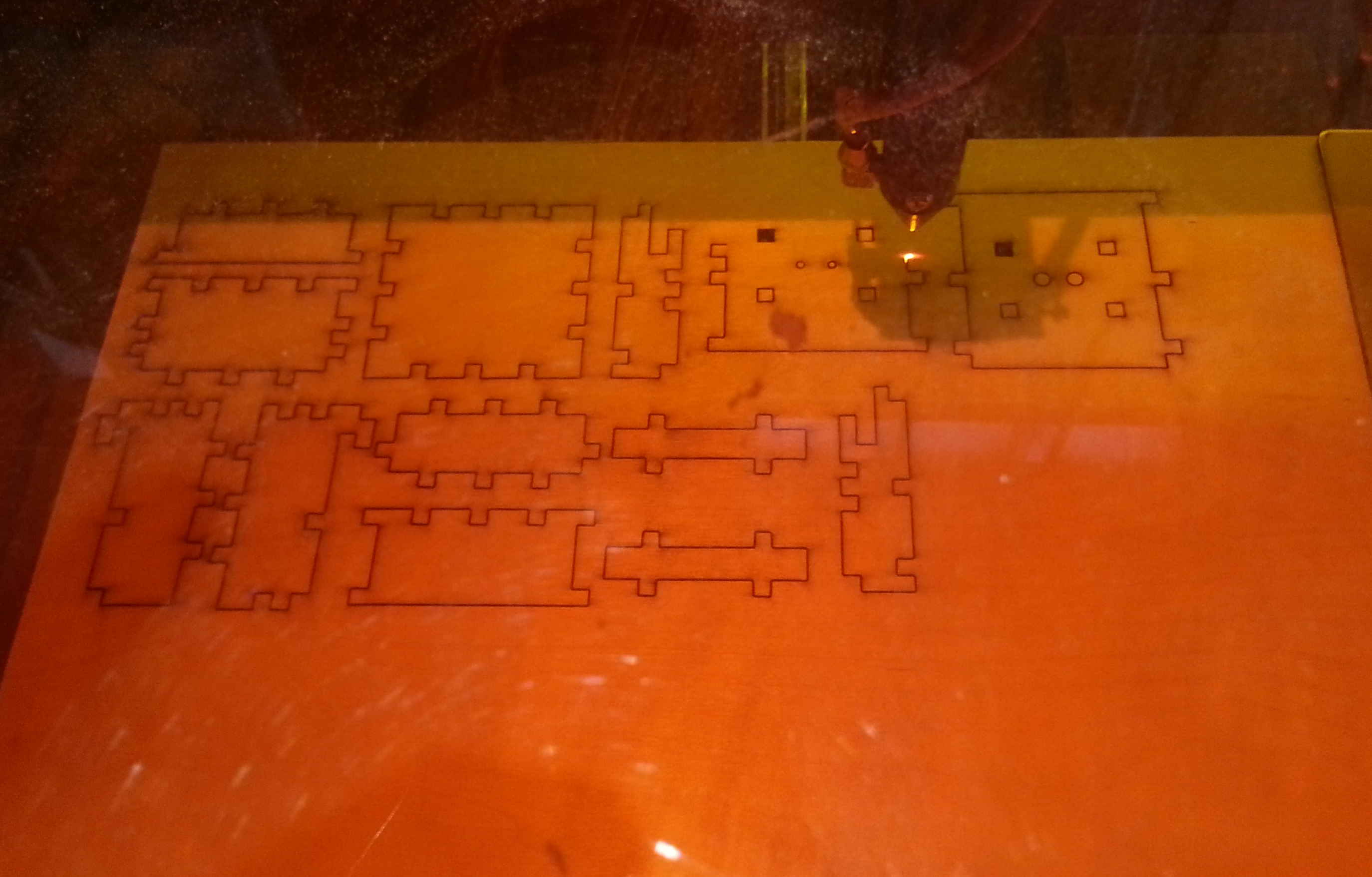
The choice of material was one that had to be robust enough to
withstand being driven and knock around whilst being quick and easy to
develop. My initial choice was to use laser cut 6mm ply as it
enabled rapid prototyping of the product. In the future, his
could be made for injection moulding or vacuum formed rigid plastic
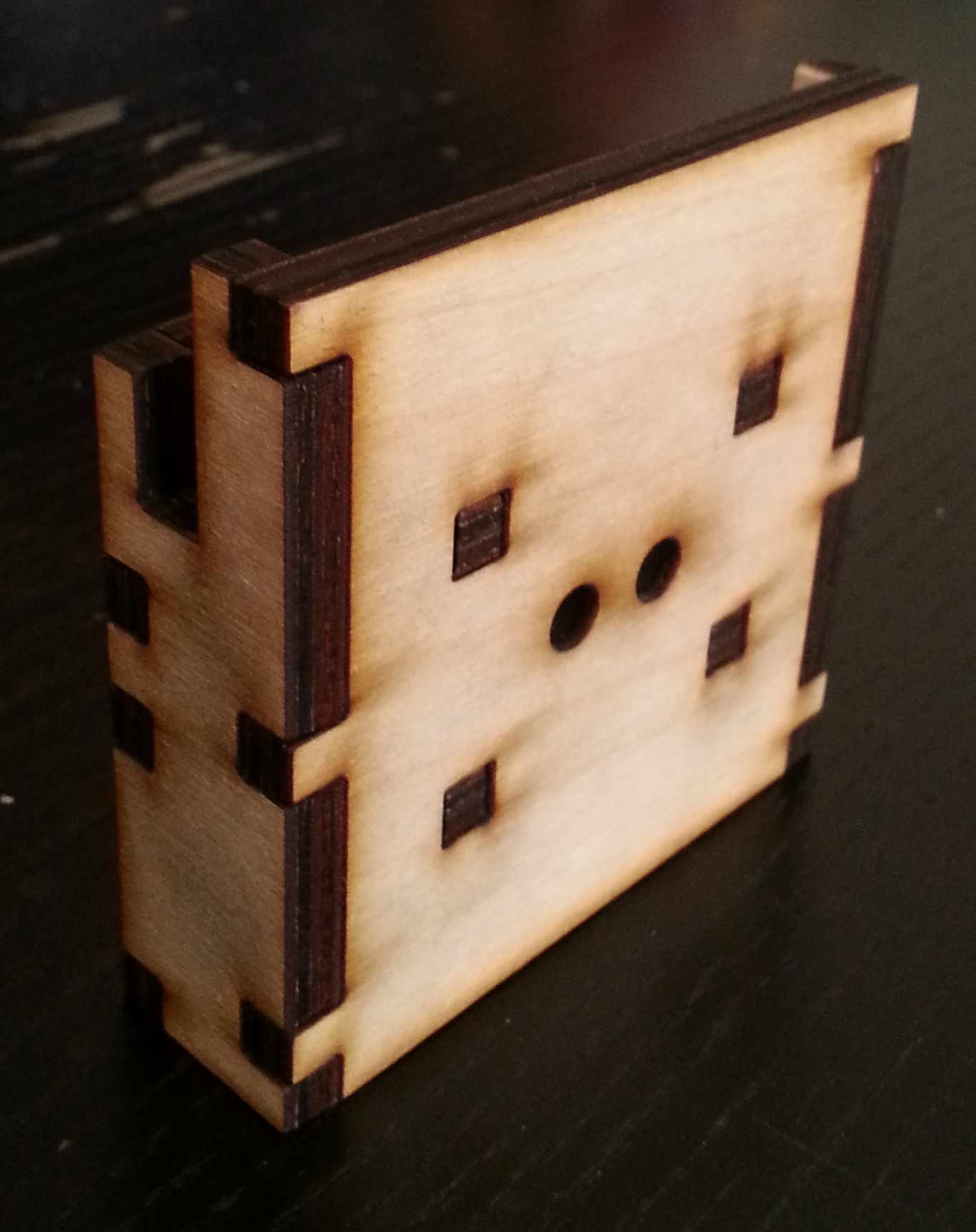
casing. For the original casing design I decided to produce a
snap fit ply wood model of the case for easy construction. The final .dxf vector file can be found here.
What I have still left to do?
For
the following week I need to mill and stuff the circuit boards once all
the components have arrived that are not in the Fab Inventory.
Mount the board in the case, potentially using some 3D printed lugs to
fix the board in place. Develop the moisture sensoring prongs, I
was thinking of using needle value pump adaptors as an immediately
available source of metal prongs that could be mounted in the sensor
box. Additionally I need to construct the embedded programming and
develop the python interface to read and calibrate the moisture sensor.
Project dissemination?
The
project is being posted in an open source atmosphere, so it stands to
reason that access to the complete source package should be easily
achieved through my Fab Academy pages. This should aid people who
are trying develop projects with multiple sensors and an application
interface - Hopefully through a wireless network!
|