Final Project
Week 0: Digital Fabrication Principles and
Practices
Week 1:
Collaborative Technical Development, Documentation and Project
Management
Week 2:
Computer Aided Design
Week 3:
Computer Controlled Cutting
Week 4:
Electronics Production
Week 5:
3D Scanning and Printing
Week 6:
Electronics Design
Week 7:
Moulding and Casting
Week 8:
Embedded Programming
Week 9:
Computer Controlled Machining
Week 10:
Input Devices
Week 11:
Composites
Week 12:
Interface and Application Programming
Week 13:
Output Devices
Week 14:
Networking and Communications
Week 15:
Mechanical Design and Machine Design
Week 16:
Applications and Implications
Week 17:
Invention, Intellectual Property and Income
Week 18:
Project Development
Week 19:
Final Project Presentation
|
Project Development
Progress
of the final project has significantly slowed due to the fustrations of
the past week. I began rethinking how I am able redesign my
project and develop it iteratively through small chunks of already know
processes. Therefore, I decided to adapt the transmit receive and
temperature the input boards from Week 10 to form a network in conjunction with a Hello Arduino
controller. Essentially, this is the same processes that I tried
to incorporate into a previous larger board but broken down into chunks
which I am able to debug and troubleshoot a lot easier. The idea
of using an RF component hasn't been neglected completely as I believe
once I am able to get the three electronic parts (i.e. Arduino, Temperature Board & TxRx board)
communicating with one another over a network I can implement and
integrate the RF component more easily - Although this element will be
wholly time and commitment dependent.
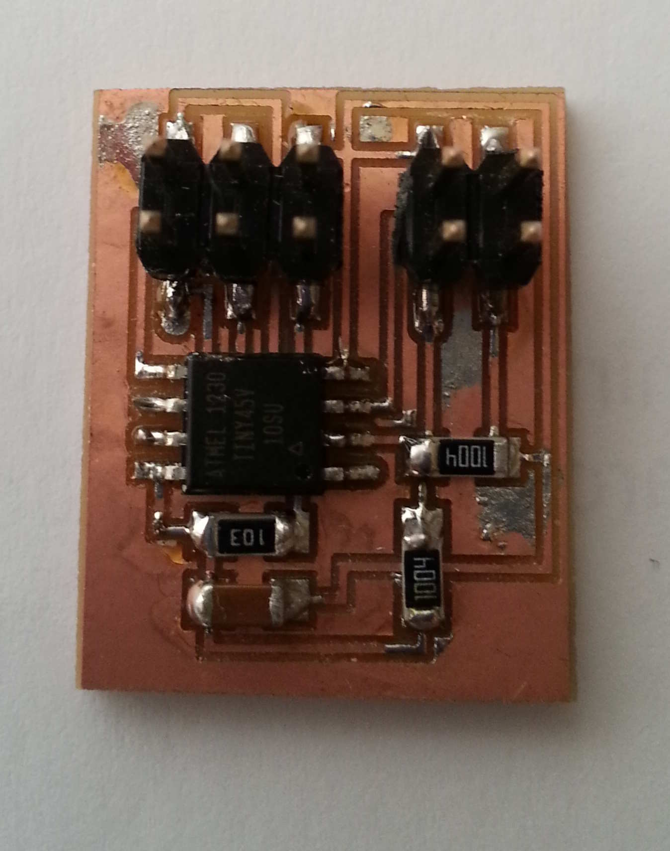
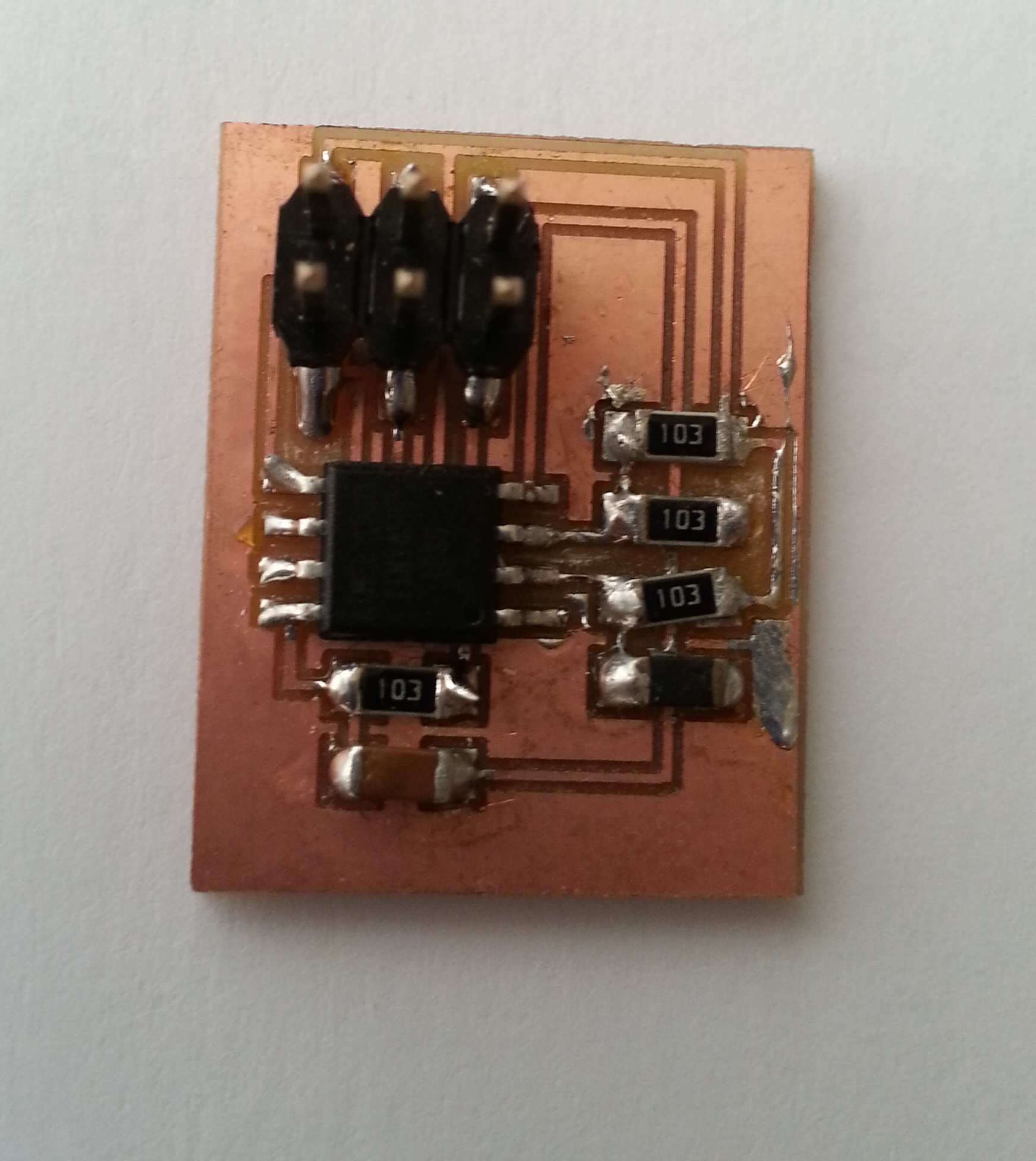
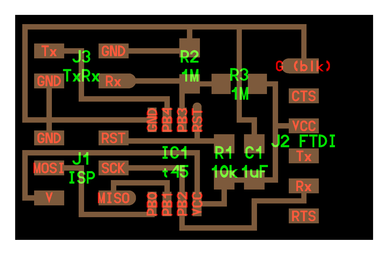
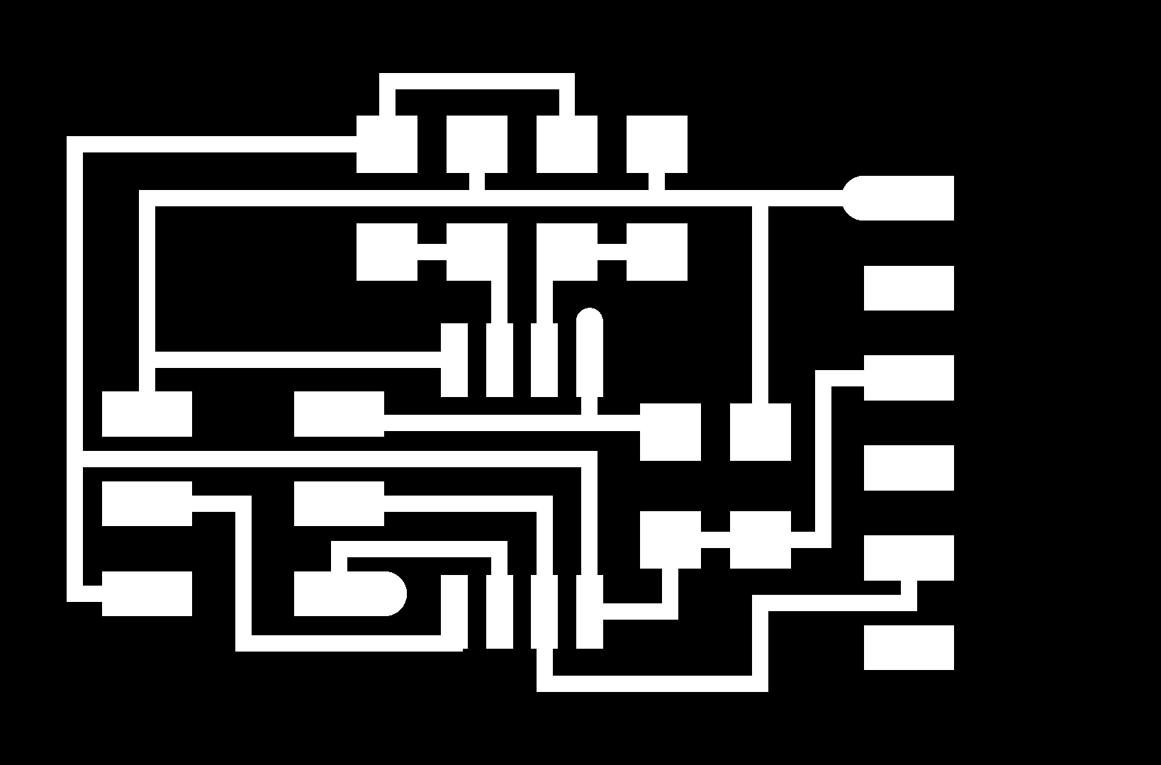
Electronics re-appraisal:
Using the monochrome .png's of the Temperature and TxRx boards
I removed the FTDI jumpers within GIMP to reduce the size of the
boards. I milled the boards using the previously defined
protocols in Week 4.
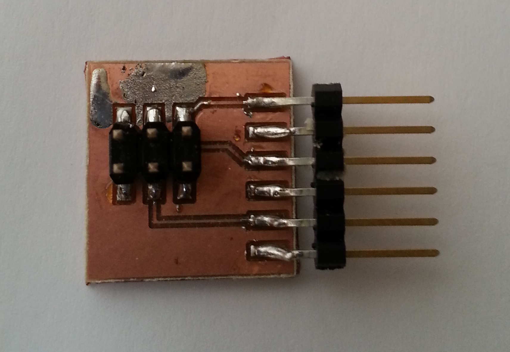
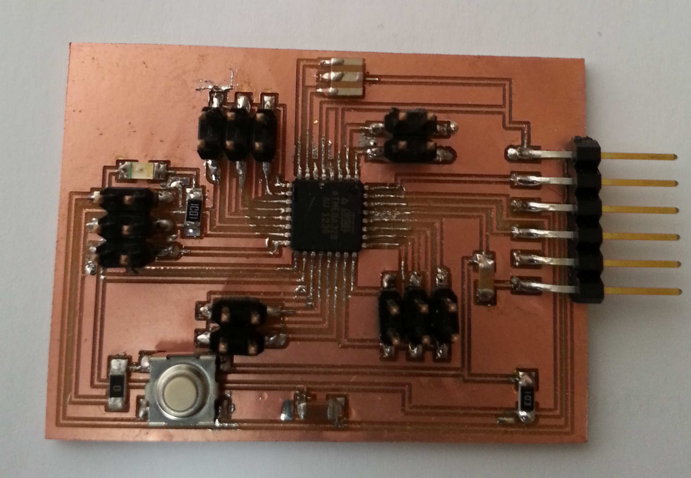
After milling and stuffing the boards I realised to enable me to
potentially troubleshoot the boards it was necessary to provide a
facility to read data coming off from the individual boards
independently, so I also constructed a simple FTDI to 6 pin jumper
breakout board.
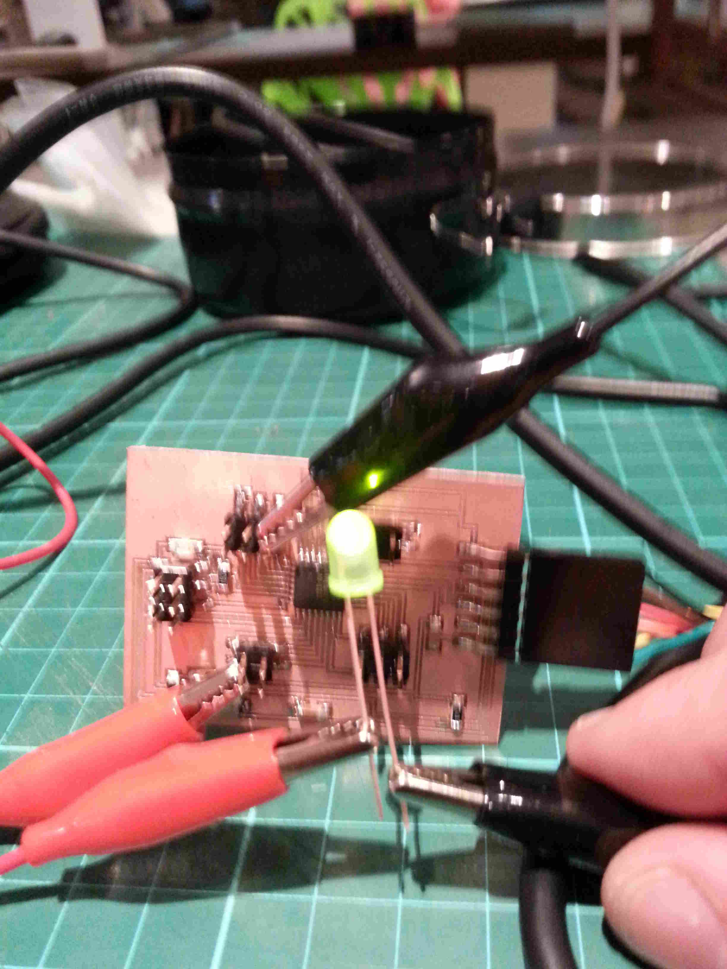
Once I had achieved this, I flashed the boards with the example C codes in Week 10
to check they were working and used the FTDI breakout to check that
these boards were functioning correctly through the graphical
application also available in Week 10.
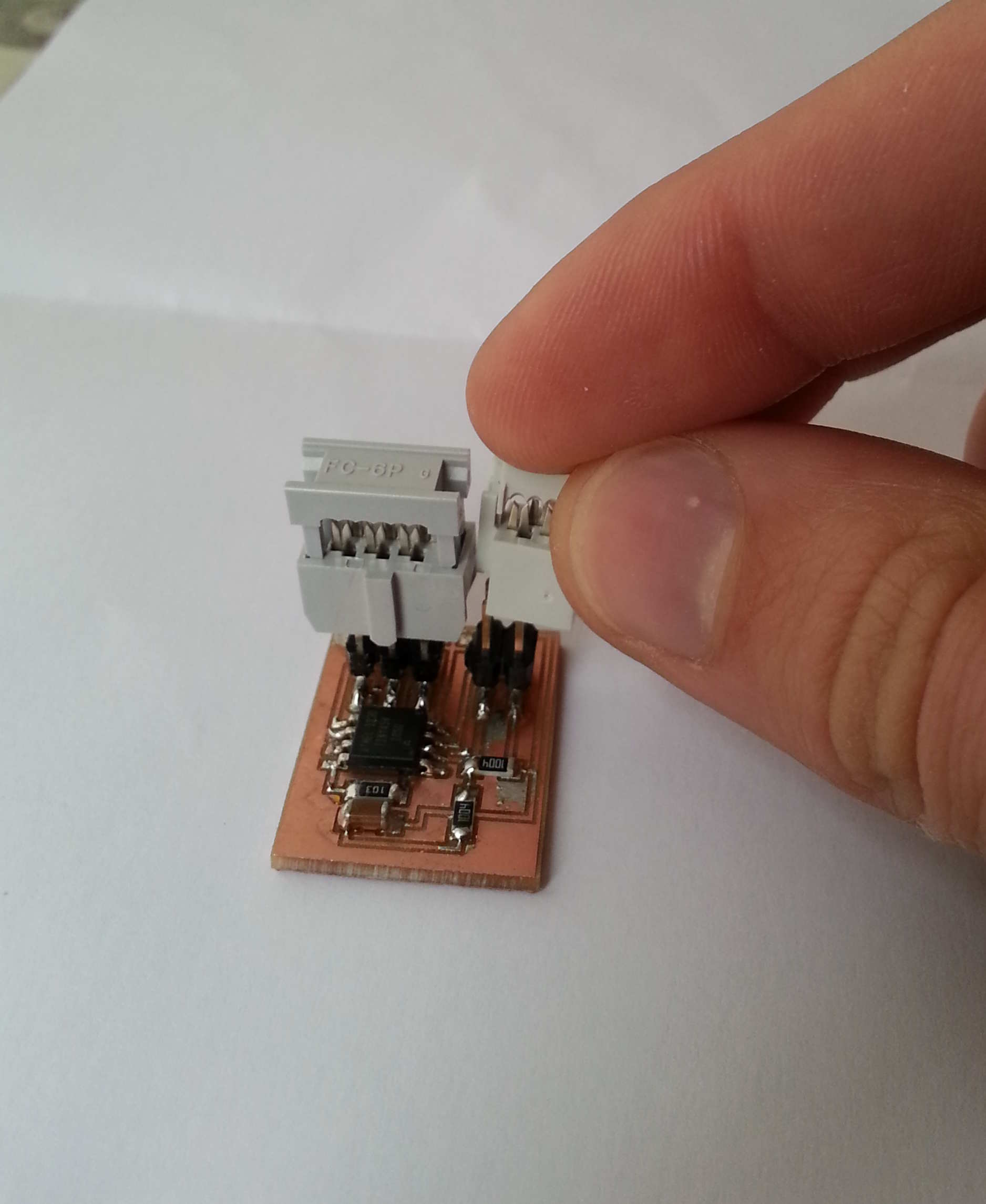
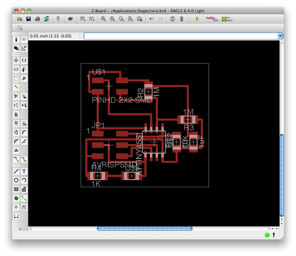
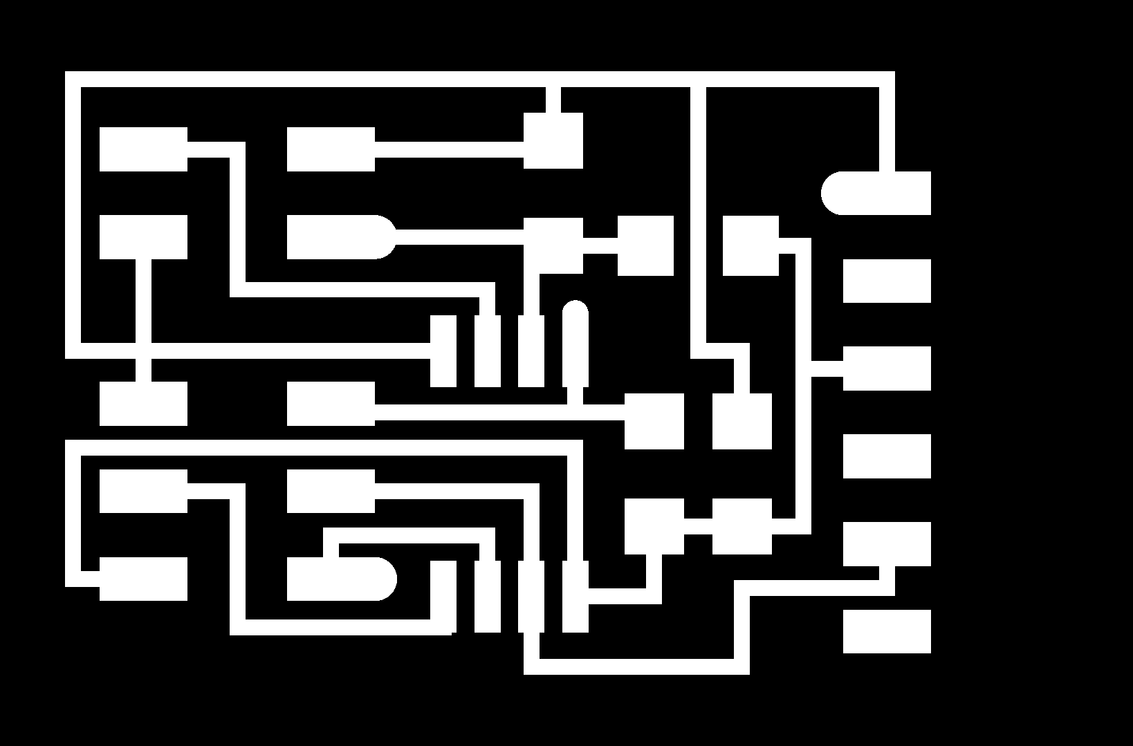
Unfortunately, the TxRx board functioned correctly but I noticed that
if I were to connect both jumpers (i.e. the 4 & the 6 pin)
with the robust plastic female headers, I couldn't! So I had to
redesign the TxRx board within in Eagle to increase the distance
between the two headers.
The developing of a controller board was simple enough as I followed the Hello Arduino
given in Week 8, I went for this controller as it gave me the ability
if necessary to add the RF component to the board. I milled and
stuffed the board and flashed and uploaded a sketch through Arduino IDE
using the protocols shown in Week 17. Additionally, I uploaded the 'blink' sketch to every pin in turn to check the board was functioning correctly.
Embedded Programming (Part 1):
To allow the input boards to work over a network, I added the networking code shown in Week 14 to the embedded programming of the input board. Firstly, here for the temperature board and here
for the moisture sensor board, with the .make files, here & here. Here I had to change the input
pins and the output pins to coincide with the program I will be
implementing for the controller board. I decided just to change
te existing embedded code as it gave me all the correct filenames and
protocols to program the inputs through AVR. Note I had to
redesign my FTDI to 6-pin jumper board as I didn't include a link to
transmit pin!
The programming of the controller board will I believe be slightly more
complicated to achieve, as I want to create a system that asks for a
reading at a set interval, which will be achieved by requesting a value
from the node ID at a given time. Once I have completed this I
will begin working up a python program to display the data in realtime
using MatPlotLib library and export the file as a .txt file to provide
further analysis. Furthermore, a calibration procedure will need
to be undertaken as the values reported from the TxRx and currently not
correct for moisture content of a timber.
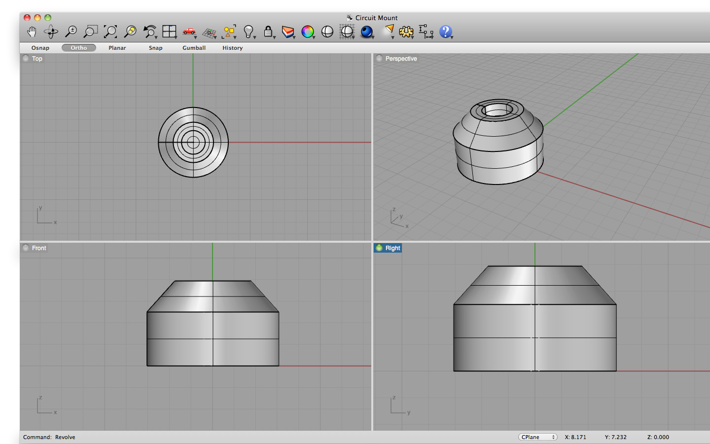
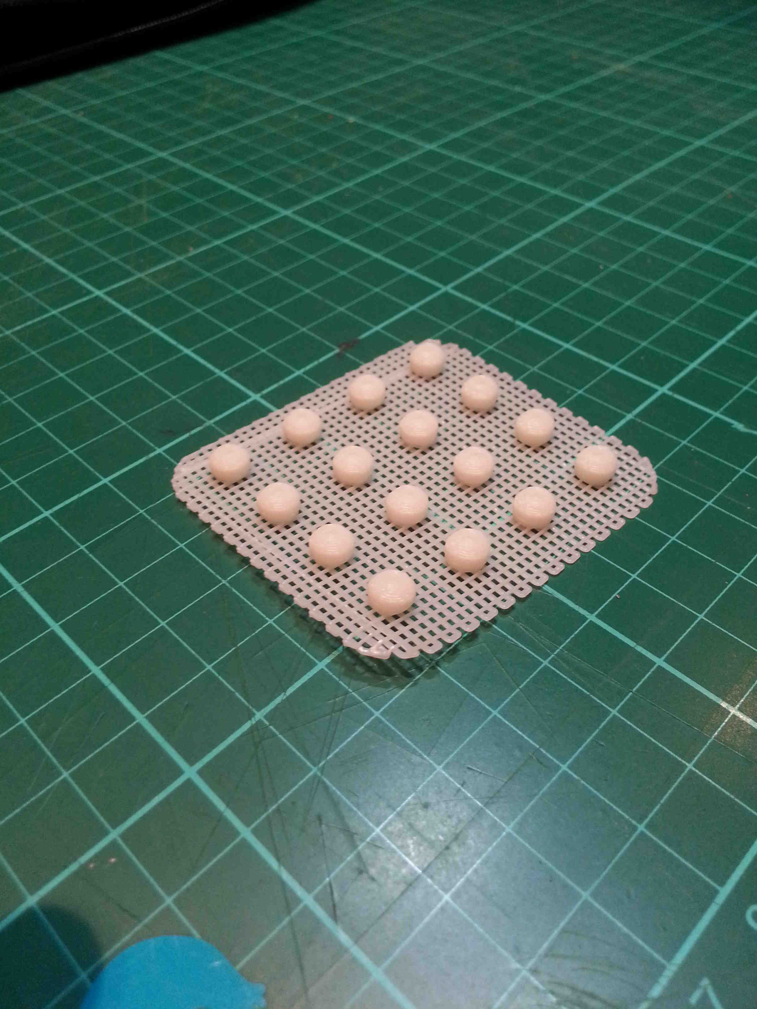
Mounting the circuits:
To mount the
circuit within the case, I decided to design small lugs in Rhino that
were then printed out using a 3D printer from this .stl file
that can simply be glued to
the circuit board and fixed to the casing to allow wires to pass
underneath the circuit where necessary (this was necessary in the
previous electronic design).
What I have still left to do?
Develop
the moisture sensoring prongs, and continue with the embedded
programming for the Controller and design the Python program to display
the realtime results.
For Final Project Report Click HERE
|