Final Project
Week 0: Digital Fabrication Principles and
Practices
Week 1:
Collaborative Technical Development, Documentation and Project
Management
Week 2:
Computer Aided Design
Week 3:
Computer Controlled Cutting
Week 4:
Electronics Production
Week 5:
3D Scanning and Printing
Week 6:
Electronics Design
Week 7:
Moulding and Casting
Week 8:
Embedded Programming
Week 9:
Computer Controlled Machining
Week 10:
Input Devices
Week 11:
Composites
Week 12:
Interface and Application Programming
Week 13:
Output Devices
Week 14:
Networking and Communications
Week 15:
Mechanical Design and Machine Design
Week 16:
Applications and Implications
Week 17:
Invention, Intellectual Property and Income
Week 18:
Project Development
Week 19:
Final Project Presentation
|
Project Development
This
week mainly of working on the group project and the final project in
tandem. Presently, it has been very difficult to get everyone
together in one room to build the machine cooperatively at any one time
and iron out any potential bugs the machine will inevitably have.
Group Project:
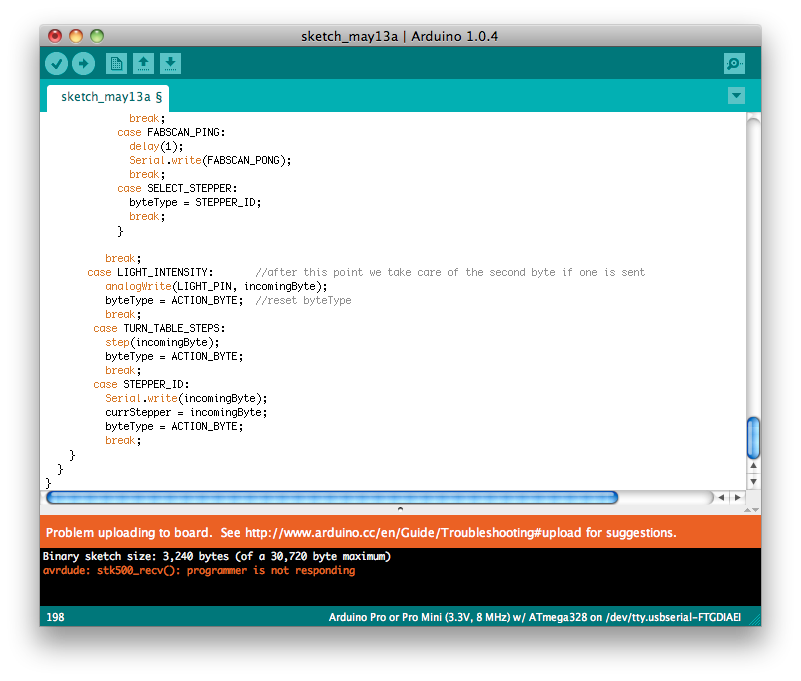
Being
unable to program the Hello Arduino in the Arduino environment proved
extremely troublesome and time consuming as my knowledge of C is
limited. Changing operations such as pinMode and Digitialwrite
were eventually found but I gave up trying to alter it extremely
difficult. I decided to try to play around again with trying to
get a sketch uploaded through Arduino, this was the first error message
I got when I had previously burnt the bootloader with AVR and tried to
program within the Arduino environment.
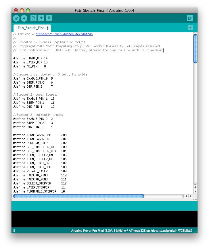
Firstly, I soldered on a 8mhz crystal and tried to burn the bootloader
in the Arduino IDE. Due to the fact that the 328 in the fab lab
inventory is not supported directly thorough Arduino, you will get an
error message stating that the expected signature is wrong.
Therefore, the AVR configuration file within Arduino must be altered to
trick the system into thinking that you have the correct chip in place.
After navigating to this file:
/Applications/Arduino.app/Contents/Resources/Java/hardware/tools/avr/etc/avrdude.conf
Open using a text edit and alter the signature for the ATMEGA
328p. The last entry of the signature line must be changed from
0x0F to 0x14 and saved. Once this is done you should be able to
burn the bootloader through Arduino, once you have selected Arduino Pro
or Pro Mini (3.3V, 8MHz using Attmega 328) as the board and all the
cable attached correctly. Once the bootloader is burnt you must
enter the config file and change the signature back to 0x0F to enable
sketches to be uploaded. After the success of uploading a sketch
to the Ardunio, me and Roy began testing the board to ensure all the
pins worked and they were aligned correctly in the given Ardunio
sketch. We uploaded the Ardunio blink sketch to the board,
altering the pin number designation each time.
Through this process, we realised that some of the pins would be
doubled up with the serial connection, so altered the pins
accordingly. Additionally, we found at couple of pins that didn't
work so altered the pins further so each output worked.
|
Afterwards,
we wanted to test whether or not the software to hardware interface
worked correctly. As we didn't possess an a computer with a OSX
of 10.8 or greater, I downloaded the older version of the software
found here.
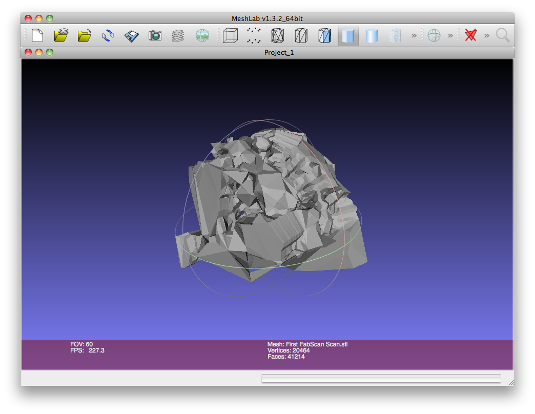
The application installed onto my computer, we tried out the scanning
capabilities of the laser. Using the logitech camera that Roy
dismantled and attaching the laser to the correct pin we attemppted a
rough scan. A rough scan, was conducted without any casing or
turntable by Roy simply holding the laser and camera and moving the
laser incrementally around the object. To our surprise it worked,
admittedly the results were incredibly shabby, but the software drove
the elements of the machine!
Next week hopefully, will get everything constructed and I might even
create a FTDI USB breakout board to remove the need for an expensive
FTDI cable to be needed for driving the machine.
Individual Project:
This weeks
individual project progress was a disaster, nothing seemed to work and
if it finally did it took an age to get working! The week started
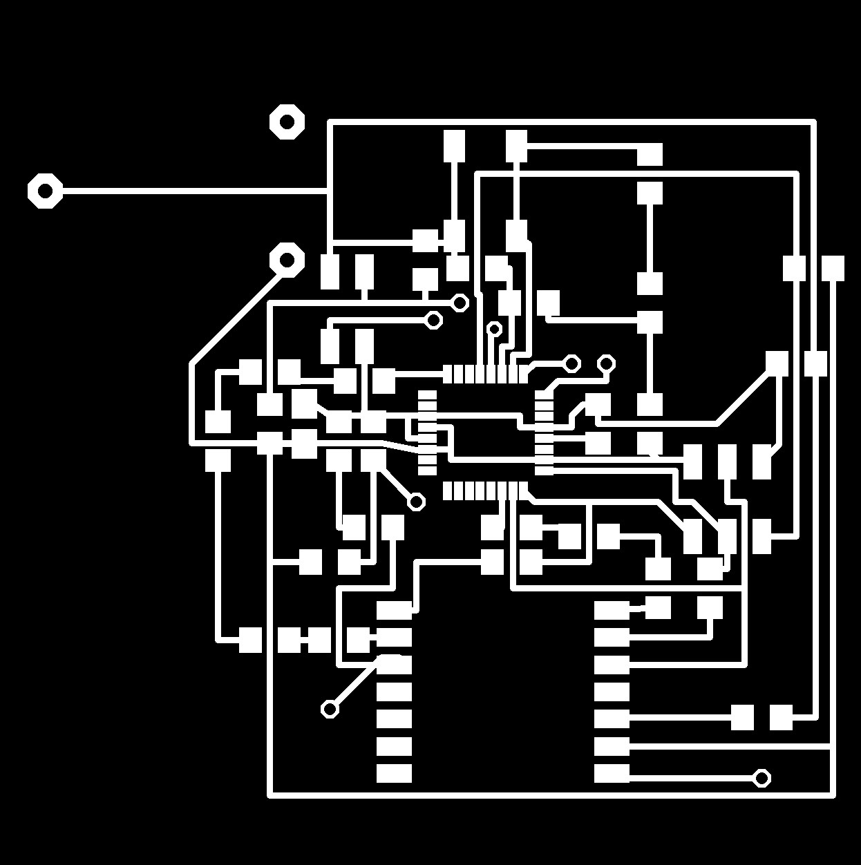
off brightly, I exported my Eagle trace layout to a .png file and
uploaded the drawing into Vcarve with no problem.
The milling of the board was a different story, it took 8 attempts and
a whole afternoon to mill out a board of a reasonable quality that I
could stuff the board. This was due to the fact that the board
was the biggest i've ever milled and if the board and the base of the
machine is not a 100% level it doesn't mill the board enough or mills
out the traces too much so that they are too thin to solder.
Eventually I stuffed the board.
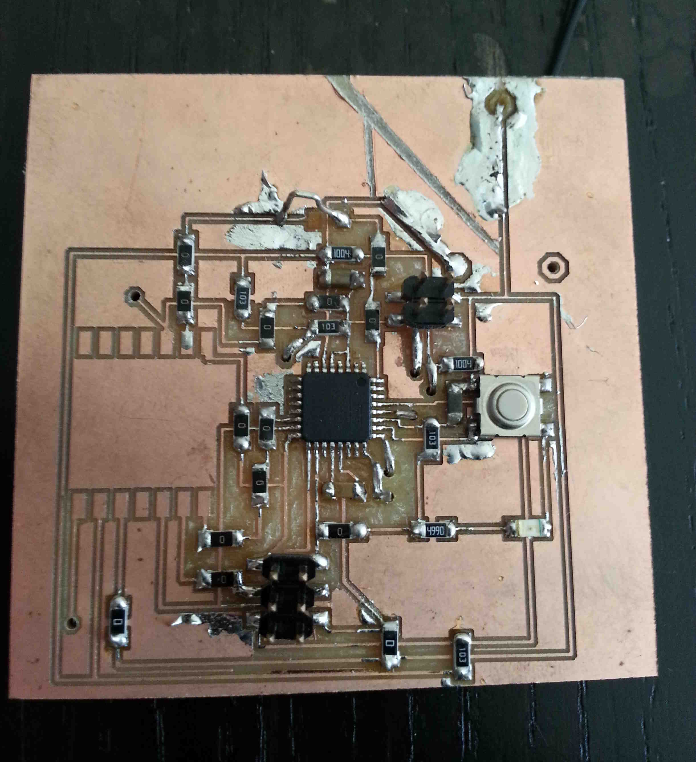
|
Unfortunately, this was only the start of my problems. Once I
plugged the stuffed board into my FabISP the chip went roasting hot and
I couldn't program the board. Admittedly I didn't leave the power
on for any length of time, as I didn't want to blow the board
completely. I thought this might be an excess of power into the
chip so I removed the 0 ohm resistor off my FabISP, a leave the button
battery in place. This didn't generate the heat it had
previously, but it still wouldn't accept a program. An alterative
I tried was to remove the button battery, resoldered the 0 ohm resistor
to FabISP to provide power to the target board through the ISP.
After this didn't work I decided to leave it until next week as I had a
lot of other more important commitments that demanded my time.
I believe I will need to go back to the drawing board!
What I have still left to do? (The same from the previous week!!)
For
the following week I need to mill and stuff the circuit boards once all
the components have arrived that are not in the Fab Inventory.
Mount the board in the case, potentially using some 3D printed lugs to
fix the board in place. Develop the moisture sensoring prongs, I
was thinking of using needle value pump adaptors as an immediately
available source of metal prongs that could be mounted in the sensor
box. Additionally I need to construct the embedded programming and
develop the python interface to read and calibrate the moisture sensor.
|