Another project: Surface probe for a closed source CNC machines:
Note: This is work in progress, it can’t be a Fablab final project, because it has no physicals controlled output; like a motor, just inputs.
Old work, Work in progress.
 +
+ ---->
----> ---->
---->
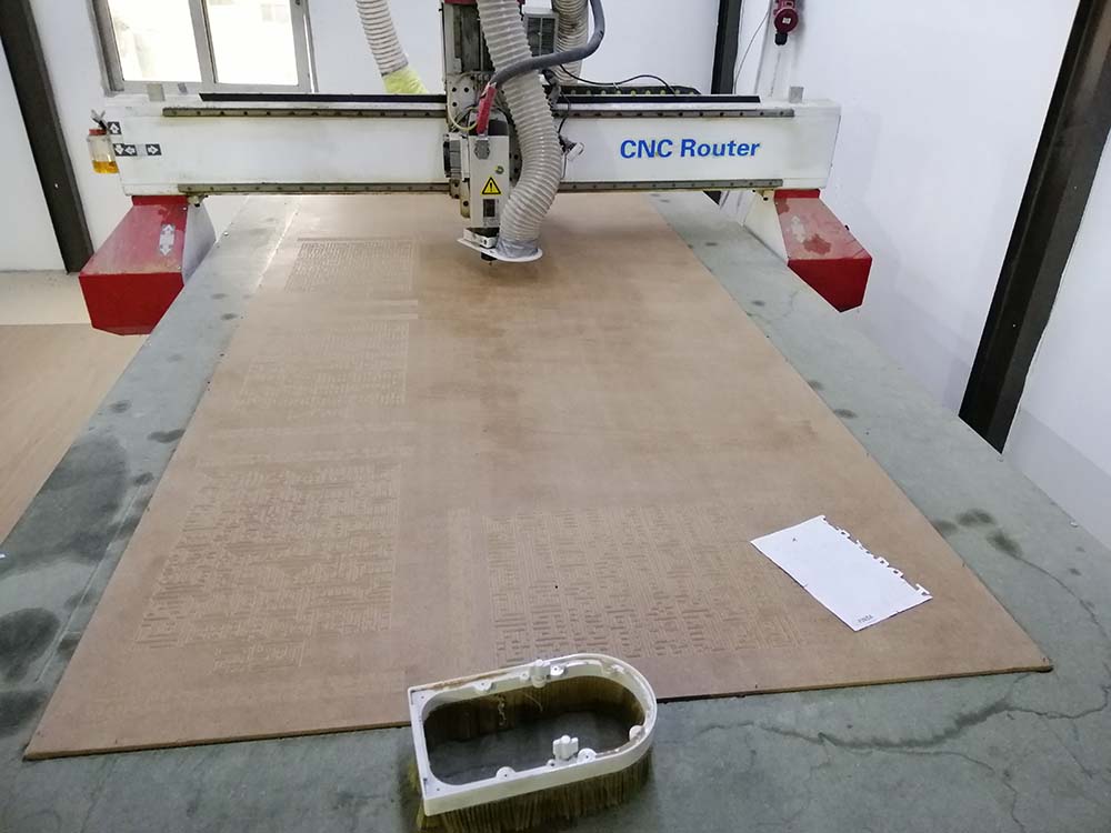
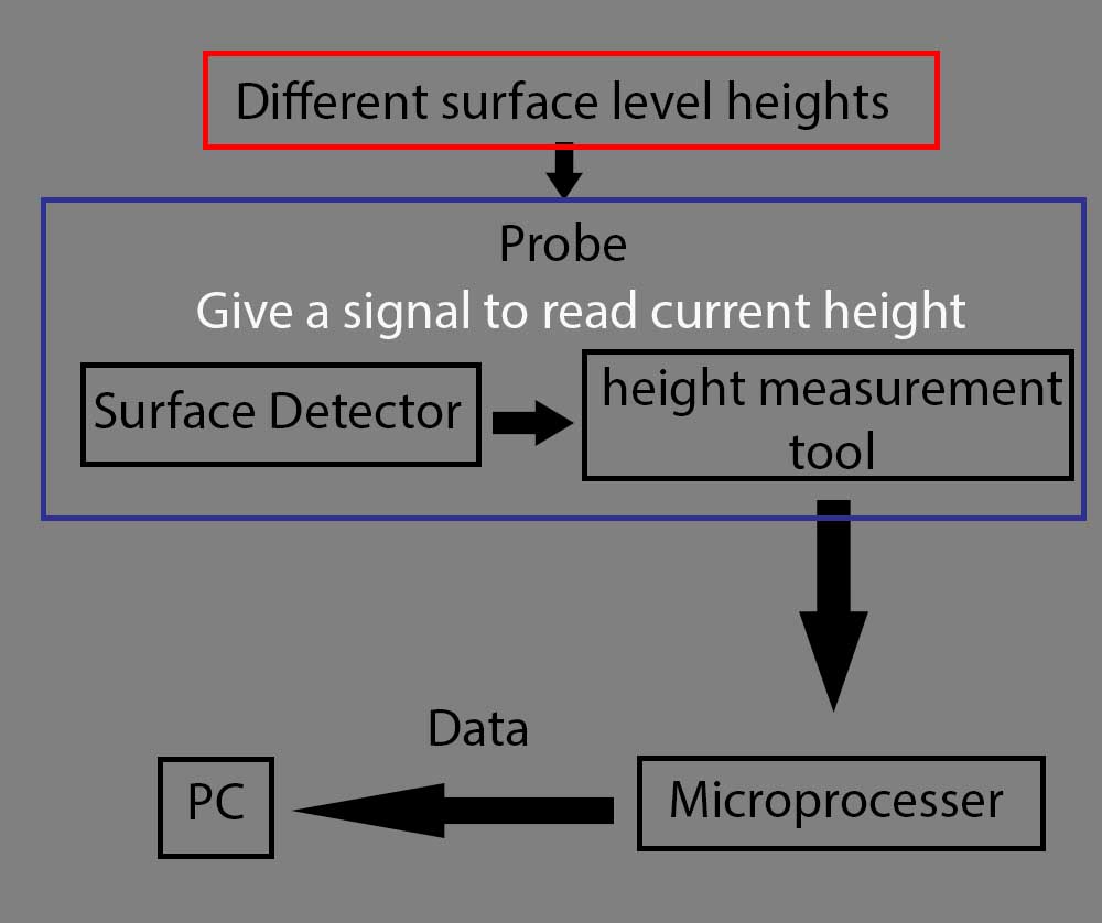
I want to make a probe that is separated from the machine Electronics, and it can automatically measure on a large CNC machine different surface/ level points across standard wooden sheet which is 2440 height and 1220 width, and send the acquired data to a PC to compensate the difference between the surface levels and g-code.
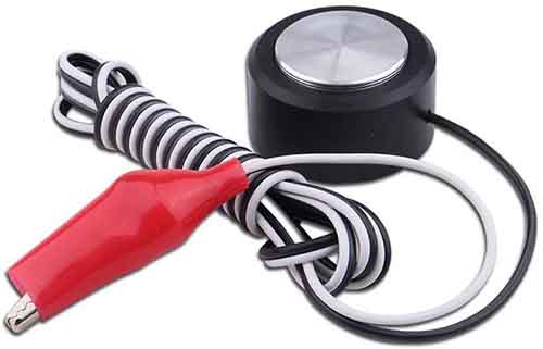
Where a simple CNC Touch Plate can not do the job if we have multiple uneven surface points, and we have to do compensate the difference manually to a program can generate g-codes.
And the another problem is that the software that comes with the CNC machine usually do not have automatic compensation and it is closed software which can not be modified.
Inspiration
While working over a year on craving and make sings and Arabic calligraphy on wooden sheets with CNC machines, I notice that even after resurface the spoilboard the surface is uneven, or on other words the Z height is not consistent.
The causes of this problem that wood will wrap due to humidity, temperature and bad storage facilities, and sometime it is hard to detect the surface in the naked eye, and margin of error is ±0.1mm too much is sometimes it too much and will take effect the on the worked piece if there were high details on them, especially the work of the operation take a long time.
Example: you can see the small change on the level surface/ height, and compare it to how it should be.
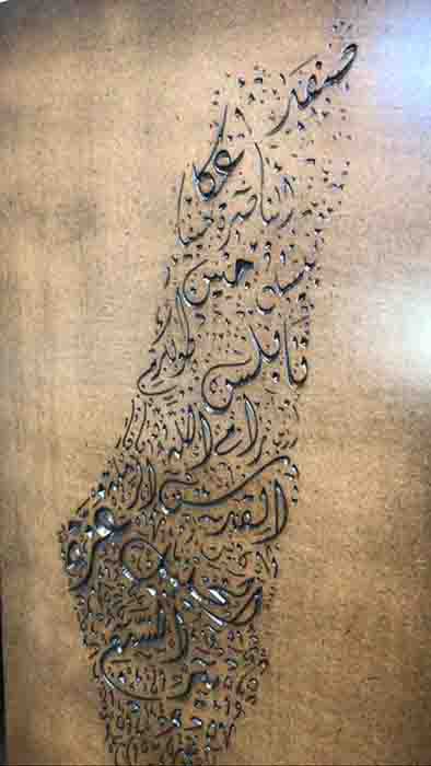

And this is how it should be:

Research
Objective: What is it to be done?
Sketch
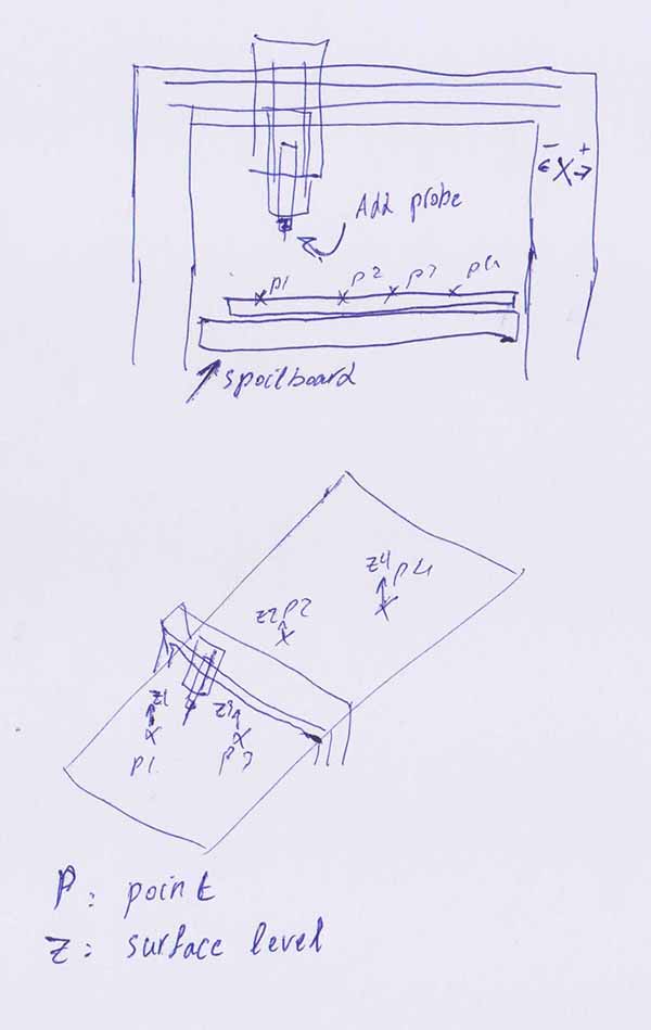
Shows the points on a stander sheet and distance between them are large.
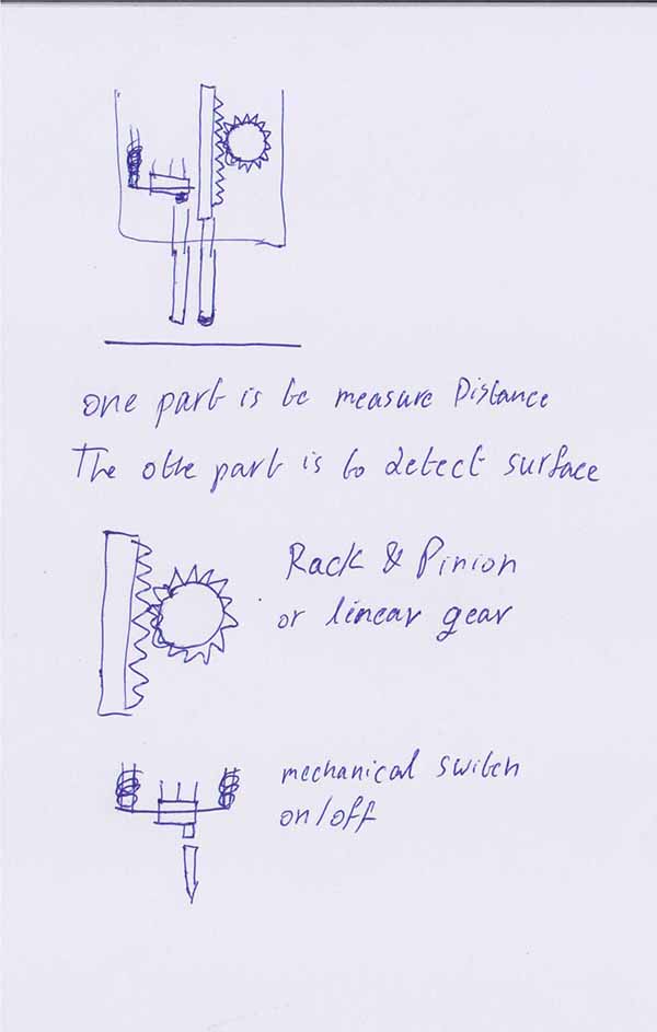
My first draft is to make it by using linear gear and mechanical on-off switch, where one detect the surface and the other is to read the difference with in small range.
Demonstrating general operation of the probe:
The general idea of measuring uneven surface of closed source CNC machine is to have two sensors, one to detect the surface, and the other is to measure the difference in height.
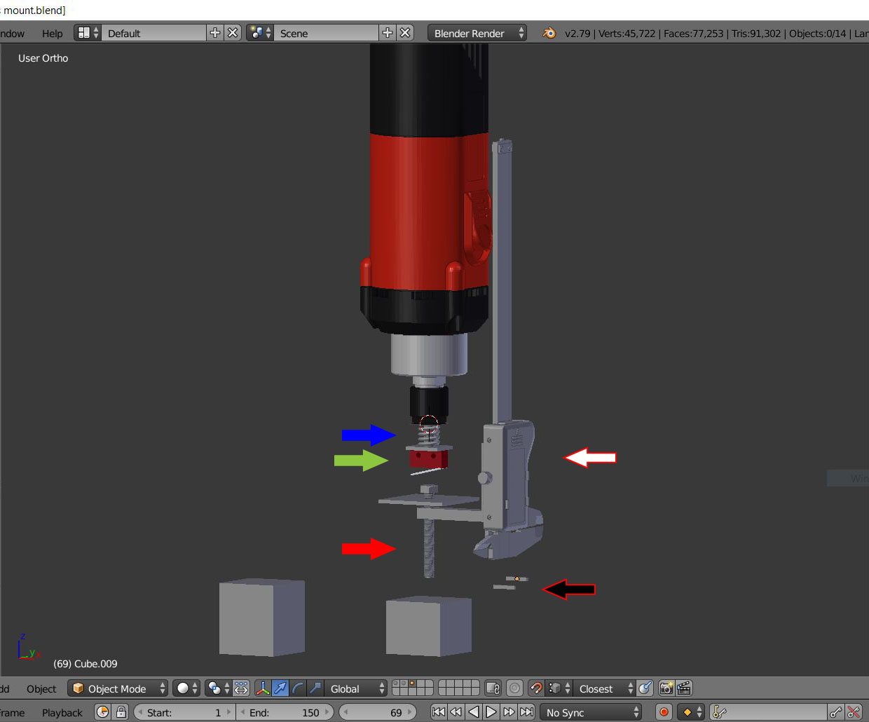
To the picture bellow:
- Blue arrow: a spring to reduce the pressure to the limit switch.
- Green arrow: limit switch.
- Red arrow: a screw; when touch the surface it will pushed to touch the limit switch.
- White arrow: a measuring tool; in this picture it is a caliper.
- Black arrow: references in heights for the animated video below.
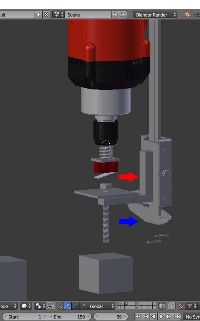
To the picture bellow:
- Red arrow: screw is attached to measurement tool.
- Blue arrow: The other part will fixed in position.
Similar option but it can not work because there are limitation:
But the problem is the program only can work on machines that use the Estelcam program, and it can not be used on other CNC machines.
2- Auto Leveling your CNC Bed manually.
He worked on an open source small CNC machine, and there is no hassle to take the surface level semi-manually unlike the large one.
And also he disconnected limit switch of the Z-axis to do this procedure.
Also we can not use it becuase the closed source of the machine.
Choosing measurement tool:
Digital caliper:
I found that we can take the readings from the digital caliper Reading Digital Callipers With an Arduino / USB from instructables.com, but we have to amplify the singal because:
The Arduino uses 5V logic but the callipers output 1.5V logic.
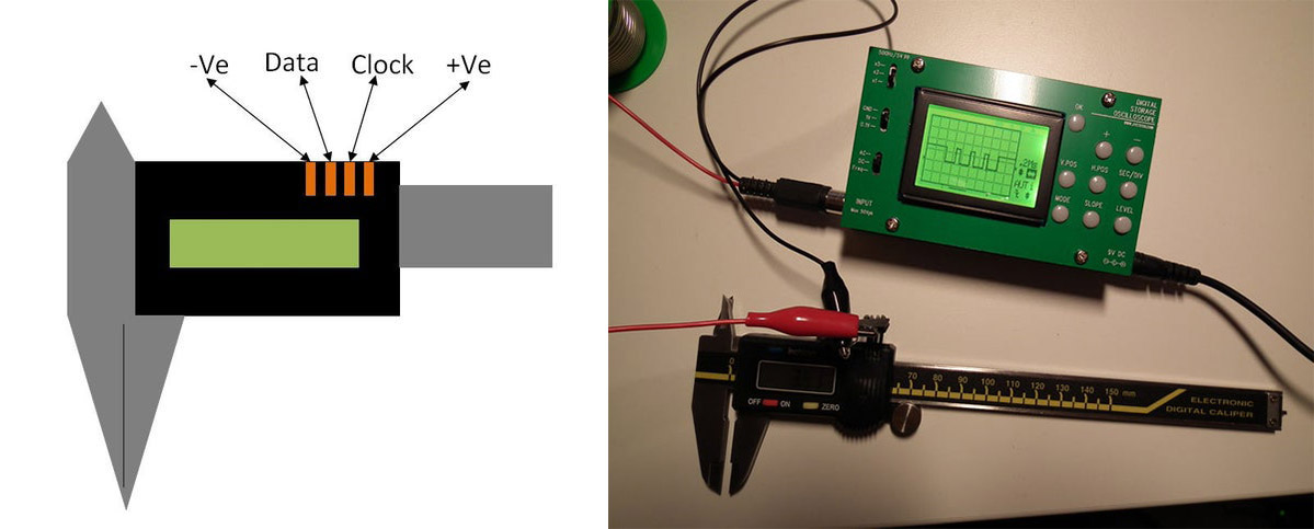
And I could use digital caliper, with the desired resolution of:
Resolution: ± 0.0005” / 0.01 mm
Slide Pot (potentiometer):
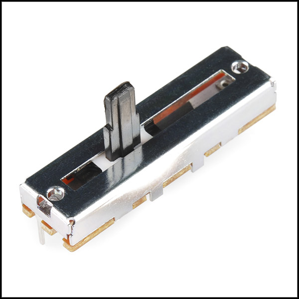
Slider Potentiometer
Slider potentiometers, or slide-pots, are designed to change the value of their contact resistance by means of a linear motion and as such there is a linear relationship between the position of the slider contact and the output resistance.
Slide potentiometers are mainly used in a large range of professional audio equipment such as studio mixers, faders, graphic equalizers and audio tone control consoles allowing the users to see from the position of the plastic square knob or finger-grip the actual setting of the slide.
One of the main disadvantages of a slider potentiometer is that they have a long open slot to allow the wiper lug to move freely up and down along the full length of the resistive track. This open slot makes the resistive track inside susceptible to contamination from dust and dirt, or by sweat and grease from the users hands. Slotted felt covers and screens can be used to minimise the effects of resistive track contamination.
As the potentiometer is one of the simplest ways of converting a mechanical positional into a proportional voltage, they can also be used as resistive position sensors, also known as a linear displacement sensor. Sliding carbon track potentiometers measure a precise linear (straight) motion with the sensor part of a linear sensor being the resistive element attached to a sliding contact. This contact is in turn attached via a rod or shaft to the mechanical mechanism to be measured. Then the position of the slide changes with respect to the quantity being sensed (the measurand) which in turn changes the resistive value of the sensor.
And from the machine design:
Resistive sensors or “pots” (short for potentiometer) are the best-known and most frequently used resistive sensors. They use a moving contact sliding against a fixed resistive element to generate changes in resistance. Hooked to a dc source as a voltage divider, they produce a proportional voltage output when used with highimpedance loads. Pots are easy to use, relatively economical, and require almost no support electronics. However, because they are contact devices, they have poor repeatability, large hysteresis, and output tends to deteriorate over time due to wear, particularly when exposed to vibrations. This makes them unacceptable for applications needing long-term reliability.
Magnetoresistive sensors, a contact-free variation on the pot, use moving magnets, thus eliminating wear problems. However they typically suffer from relatively large temperature coefficients, which are not acceptable in many applications. Both magnetoresistive and pots are available with full-scale measuring ranges from about 0.1 to 20 in. (2.5 to 500 mm).
But when I tested the out reading using Arduino, I got good results, using analogRead, and it give good resolution for the readings because it used 10bit, or in other words 2^10 which gives us range from 0 to 1023, which is a good ranges, where 8bit gives resolution from 0 to 255.
Also I kept tapping/ shaking the potentiometer, to reduce the repeatability and increase hysteresis of the readings.
Code:
const int potpin = 1;
float val = 0;      // Floating-point numbers are often used to approximate analog and
float dis = 0;      // continuous values because they have greater resolution than integers

void setup()                    // run once, when the sketch starts
{
  Serial.begin(9600);           // set up Serial library at 9600 bps

  Serial.println("Hello world!");  // prints hello with ending line break
}

void loop()                       // run over and over again
{
  val = analogRead(potpin);
  dis = (30 * val) / 1023;
  Serial.print(dis, 4);
  Serial.println("mm");
  delay(3000);
}
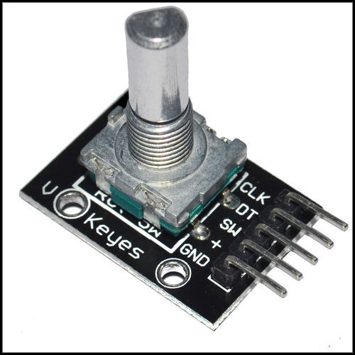
Rotary encoder with gearbox:
From Gear generator, I can make gear box where I can increase the resolution of the readings.
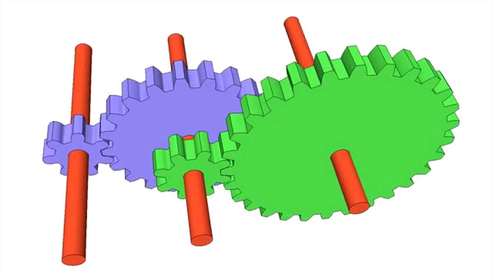
The rotary encoder has a special library in Arduino which I can use to programing using efficient interrupt routines.
Code:
const int interruptA = 0;
const int interruptB = 1;
int CLK = 2; // PIN2
int DAT = 3; // PIN3
int BUTTON = 4; // PIN4
int LED1 = 5; // PIN5
int LED2 = 6; // PIN6
int COUNT = 0;

void setup()
{

  attachInterrupt(interruptA, RoteStateChanged, FALLING);
  // attachInterrupt(interruptB, buttonState, FALLING);
  pinMode(CLK, INPUT);
  digitalWrite(2, HIGH); // Pull High Restance
  pinMode(DAT, INPUT);
  digitalWrite(3, HIGH); // Pull High Restance
  pinMode(BUTTON, INPUT);
  digitalWrite(4, HIGH); // Pull High Restance
  pinMode(LED1, OUTPUT);
  pinMode(LED2, OUTPUT);
  Serial.begin(9600);
}

void loop()
{
  if (!(digitalRead(BUTTON)))
  {
    COUNT = 0;
    Serial.println("STOP COUNT = 0");
    digitalWrite(LED1, LOW);
    digitalWrite(LED2, LOW);
    delay (2000);
  }
  Serial.println(COUNT);
}

void RoteStateChanged() //When CLK FALLING READ DAT
{
  if (digitalRead(DAT)) // When DAT = HIGH IS FORWARD
  {
    COUNT++;
    digitalWrite(LED1, HIGH);
    digitalWrite(LED2, LOW);
    delay(20);
  }
  else // When DAT = LOW IS BackRote
  {
    COUNT--;
    digitalWrite(LED2, HIGH);
    digitalWrite(LED1, LOW);
    delay(20);
  }
}
Processing the output:
The main idea to recalculate the Z-axis points, is to use this plane equation given three points.
-
a x + b y +c z + d = 0
-
→ A B = ( Bx − Ax, By − Ay, Bz − Az )
→ A C = ( Cx − Ax, Cy − Ay, Cz − Az ) -
→ A B × → A C = ( a, b, c )
a = ( By − Ay )( Cz − Az ) − ( Cy − Ay ) ( Bz − Az )
b = ( Bz − Az )( Cx − Ax ) − ( Cz − Az) ( Bx − Ax )
c = ( B x − A x ) ( C y − A y ) − ( C x − A x ) ( B y − A y )
d = − ( a A x + b A y + c A z )
I have found three open source programs can use the output data and adjust the g-codes, but the disadvantage that I have to figure out the data and mimic the correctional data.
chilipeppr.com:
Chilipeppr represents a modern way to do CNC software control for the TinyG motion controller, which you can use it in your web browser.
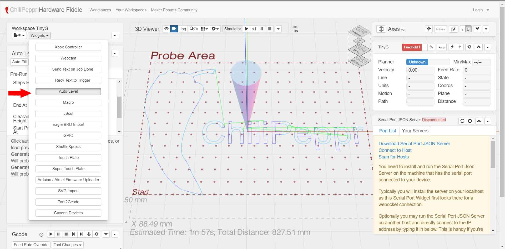
We can choose Auto-level, under the Widgets tab.
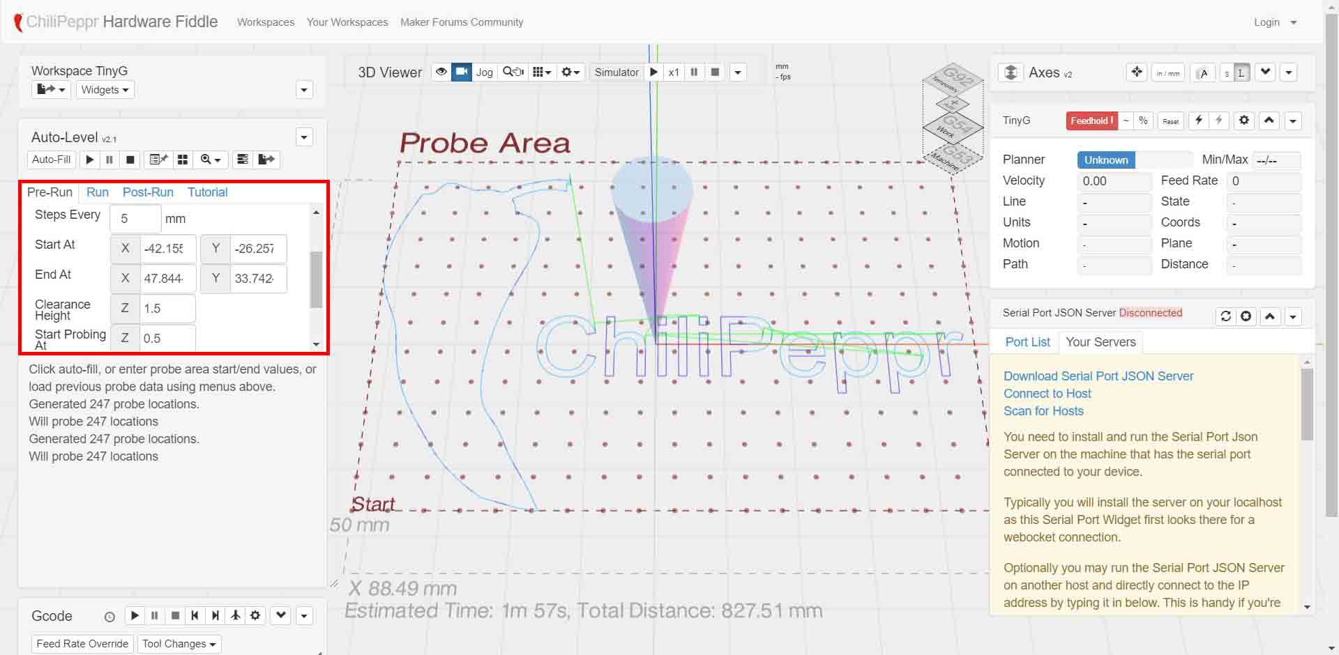
And we can mimic the machine run by entering the same values to program that can generate g-codes.
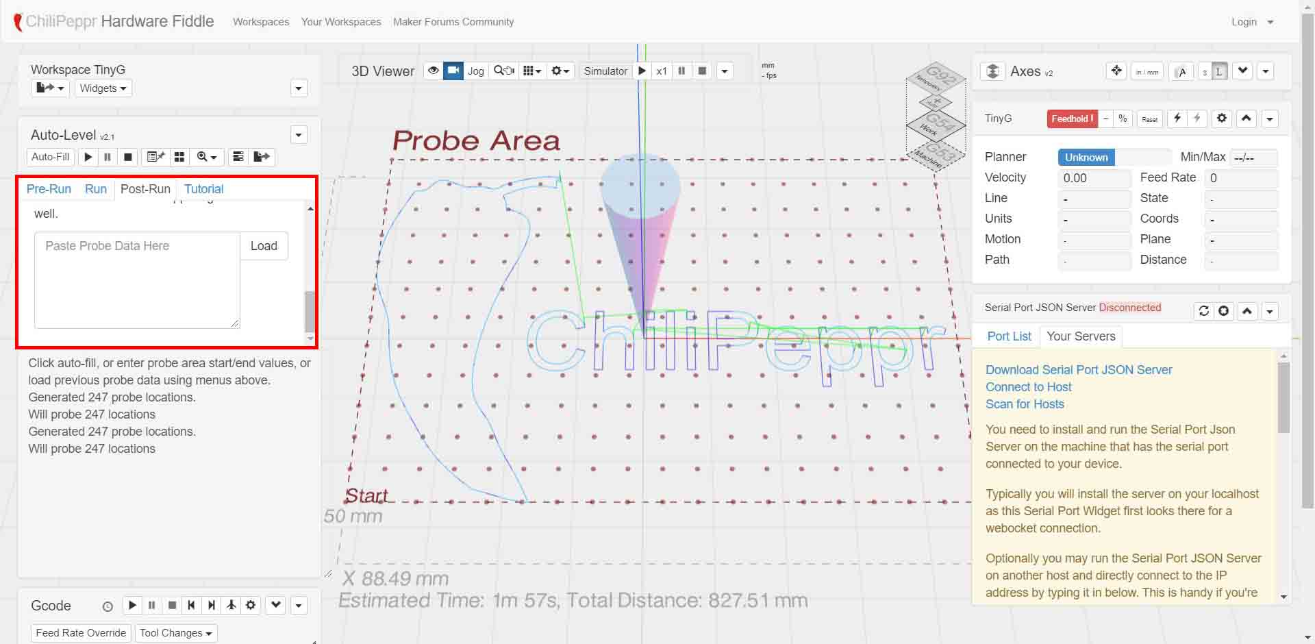
Then we can load the output data under the Post-Run.
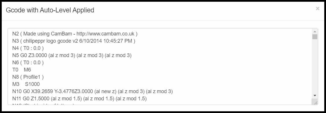
Then we can view the Auto-Levelled G-code.
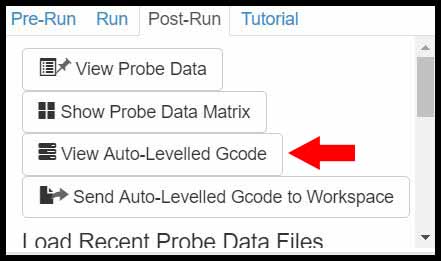
And copy the new g-code, and save it in normal file, but we must modify the start and the end of the g-code to match the large CNC machine parameters.
G-code Ripper:
G-Code Ripper is a free open source program released under the GNU General Public License (GPL) Version 3, and it is a g-code reading and manipulation program written in python.
We have the Auto Probe option, and the Recalculate button to update the parameters.
From the controller we have three options: - LinuxCNC; open source CNC controller. - MACH3 - MACH4
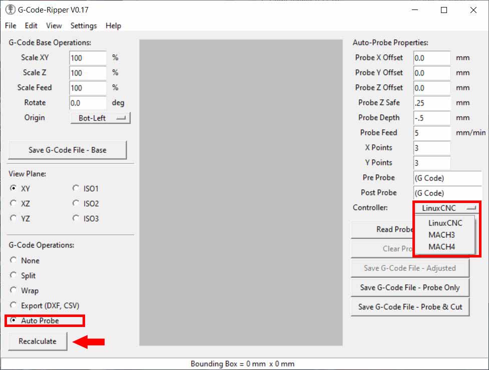
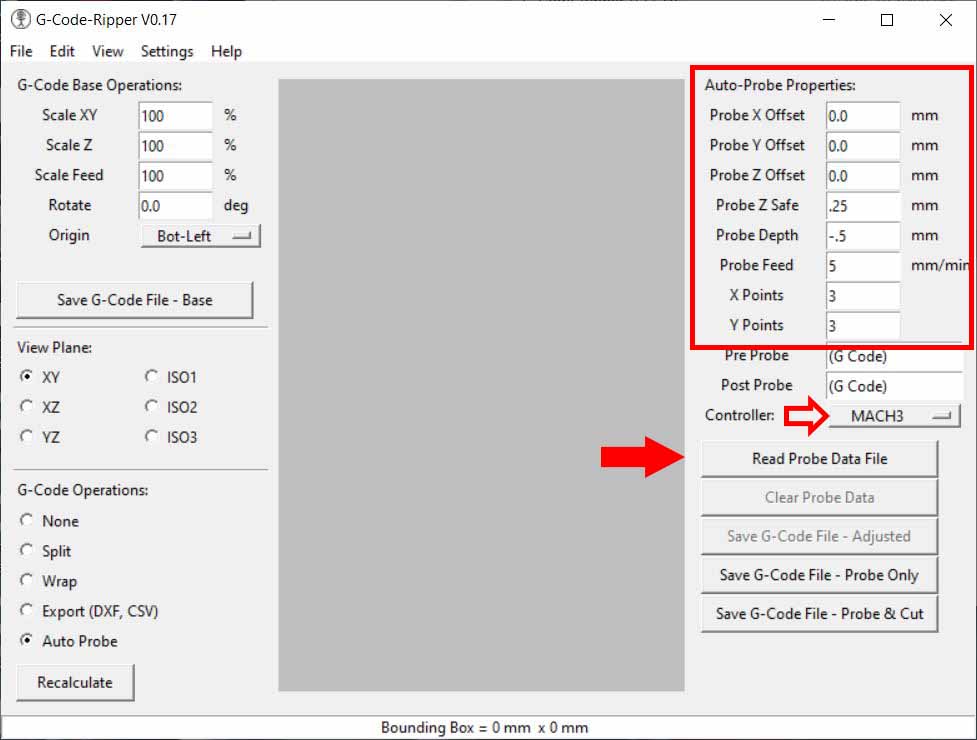
We can see from this program the Auto-Probe Properties, which we can put the offset to the probe, the feedrate and how many points it must collect.
And I have found out the MACH3 is similar to my machine code.
And the Probe Data file; that still did not figure out how to mimic it yet.
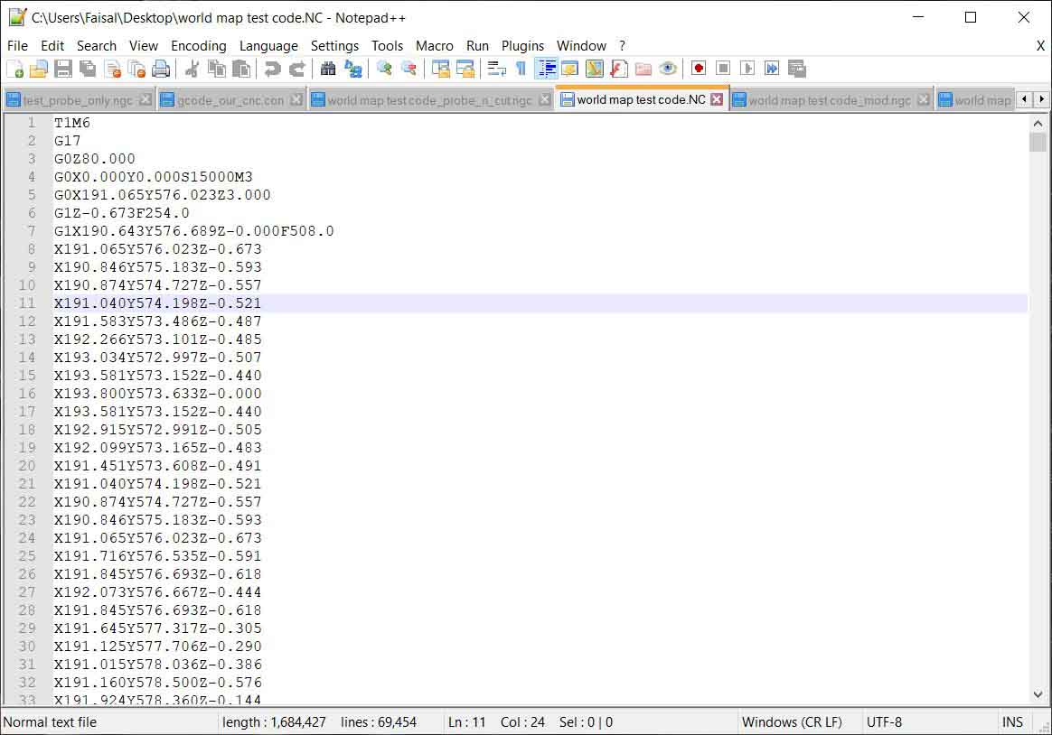
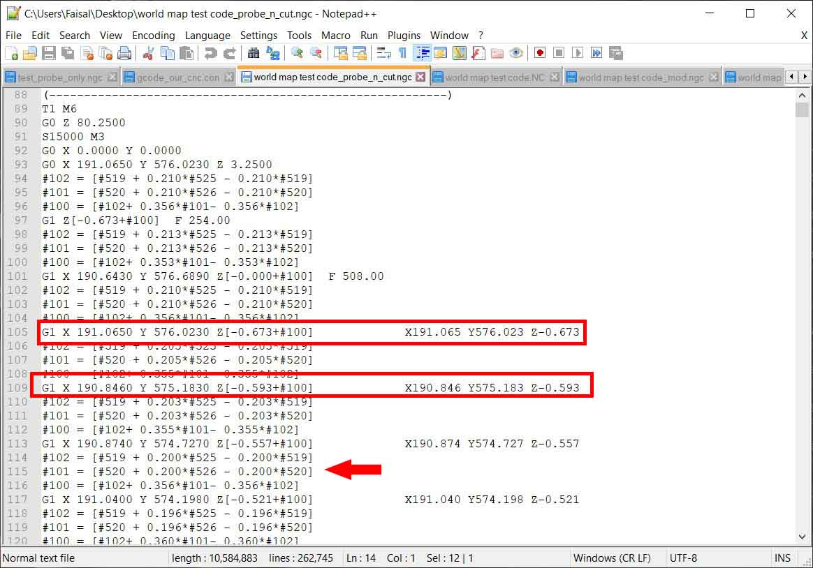
This is the probe g-code generated from the program.
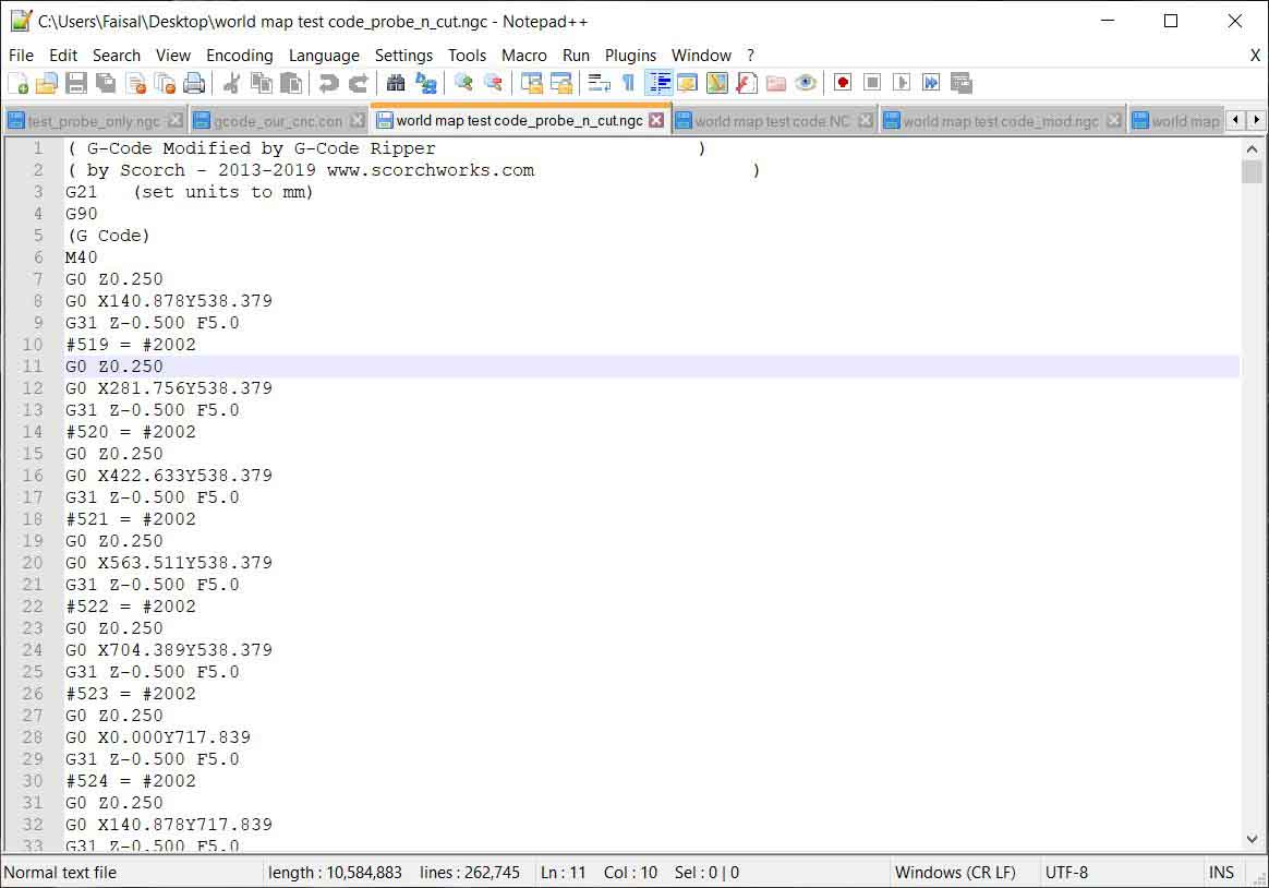
This is a g-code that I have generated from other program, notice the coordinations.
I generate a Save G-Code File - Probe and Cut, and compare the files and it shows a promising results.
autoleveller.co.uk:
Autoleveller is a correct tool depth for those points (or any point in between those points using the bi-linear interpolation algorithm).
Load the G-Code into Autoleveller and make any adjustments to the probe mesh values you need. If you are happy with those values you may not need to make any changes.
Click “Autolevel” and it will write an autolevelled version of your original G-Code file to disk. You can then just load this file into your CNC control software (Mach3, LinuxCNC etc.) and run it as you normally would.
Click “Generate PFG” and just the probing stage is written to the output GCode file; the milling / etching part will be done in a separate G-Code file. Running the file, the probe values will be written to a separate log file which can then be viewed in Autoleveller. You can then use 2-stage levelling to perform Autolevelling.
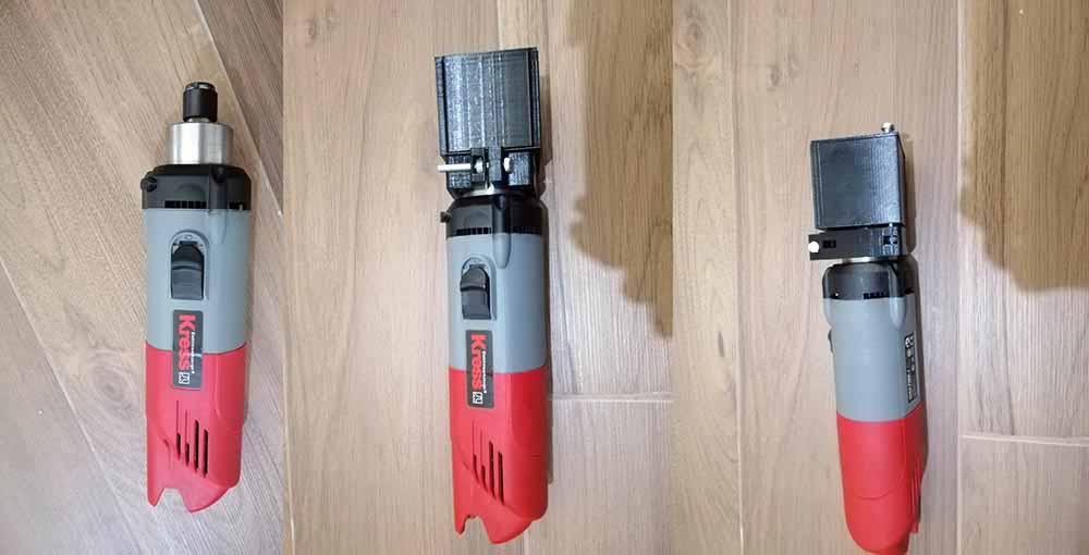
Designs attachment box to a spindle:
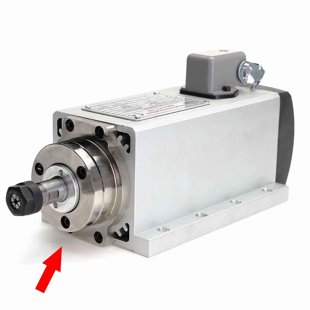
I have choosen a Kress 1050 FME-1 as a prototype, which looks similar to a CNC spindle, but smaller.
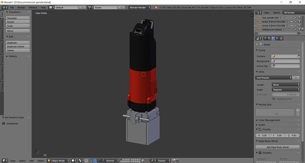
Basic designed 3D models:
I made three parts, one to be mounted, and a sliding box attached to the mount.
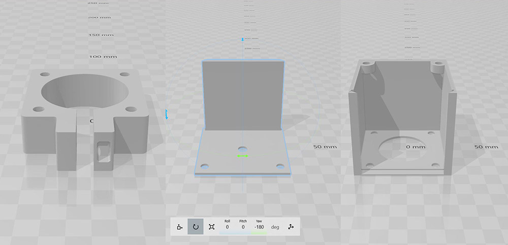
Print settings:
Different 3D printer used, with 0.5mm nozzle, with the same slice settings for all.
Quality
Layer Height: 0.25 mm
Line Width: 0.35 mm

Shell
Wall Thickness: 1.0 mm
Top/Bottom Thickness: 0.8 mm

Infill
Infill Density: 20%
Infill Pattern: Cubic Subdivision

Material Printing Temperature: 210 °C
Build Plate Temperature: 60 °C

Speed
Print Speed: 70 mm/s
Initial print speed: 10 mm/s
Number of slowed layers: 3 layers
Travel
Enable Retraction: Yes

Cooling
Enable Print Cooling: Yes
Fan Speed: 23%

Support
Generate Support: Uncheck

Build Plate Adhesion
Build Plate Adhesion Type: Skirt
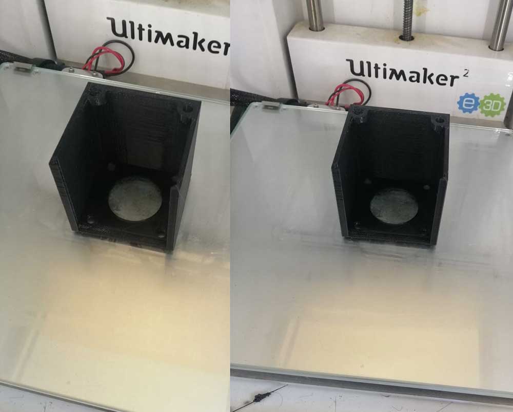
Results:
Part one from Box.
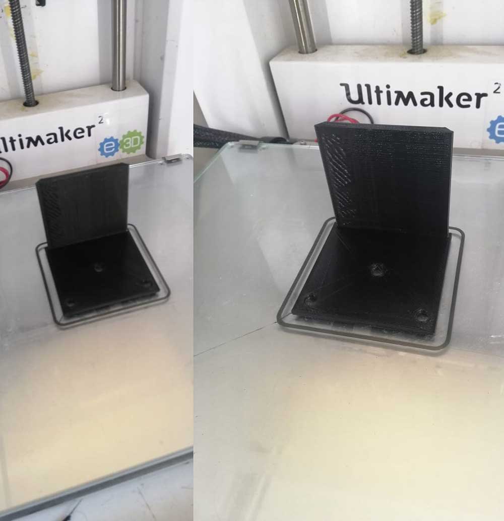
Part two from Box.
Mount to Kress spindle.
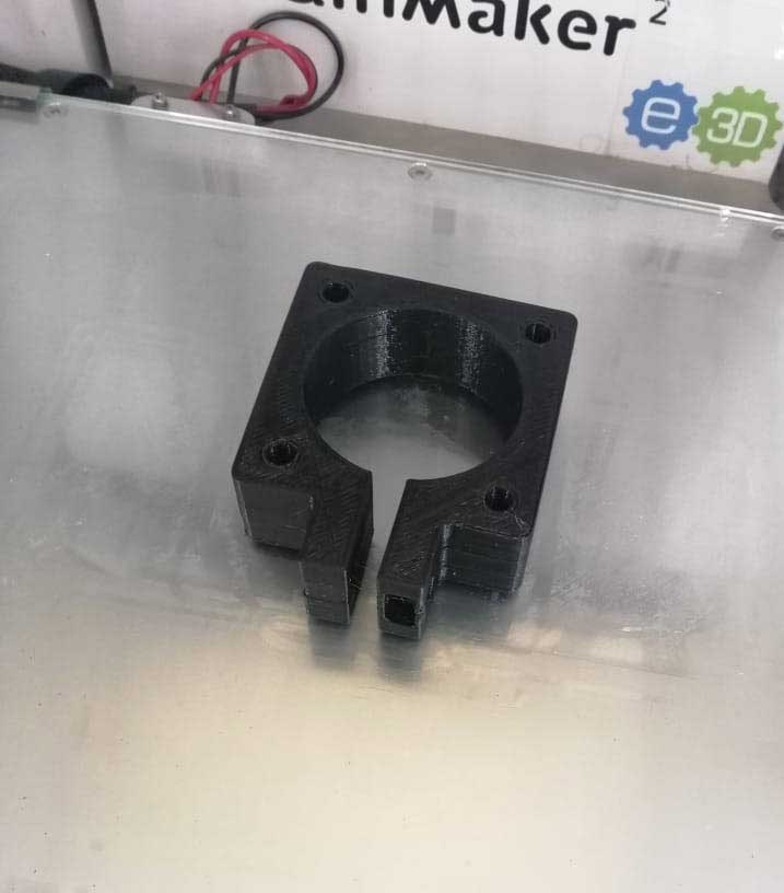
Sliding Box combined
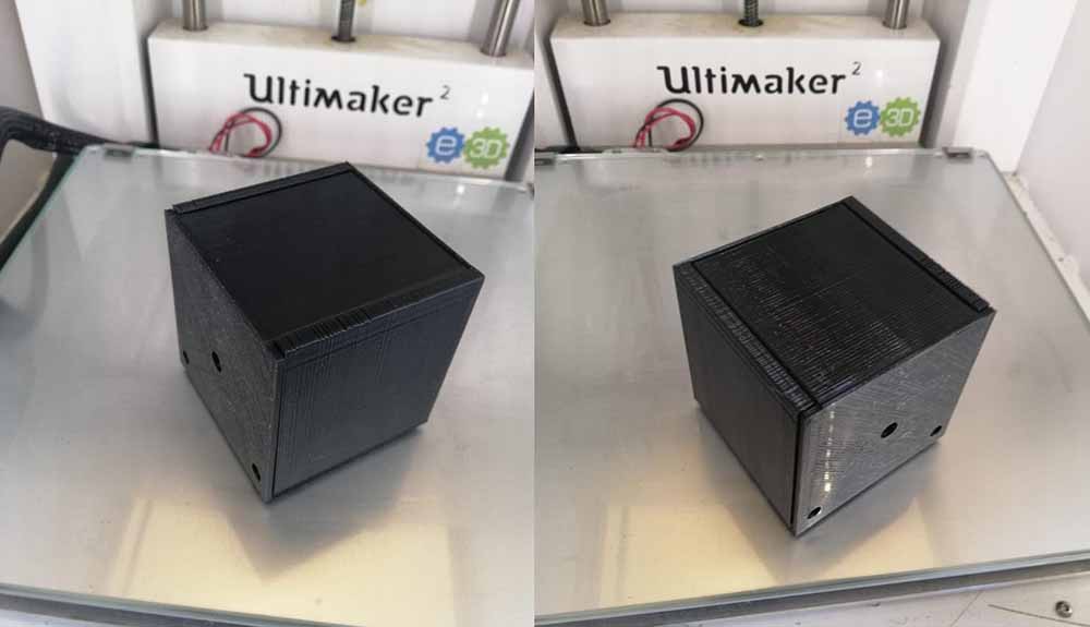
Assemble them by using M5 screws and nuts.
Hero shoot
Thingiverse Link