9. Embedded programming
Download Files:
Switch LED by Pushbutton in C and C++
Echo in C and C++ with no Pushbutton
Echo in C and C++ with Pushbutton
Group assignments:
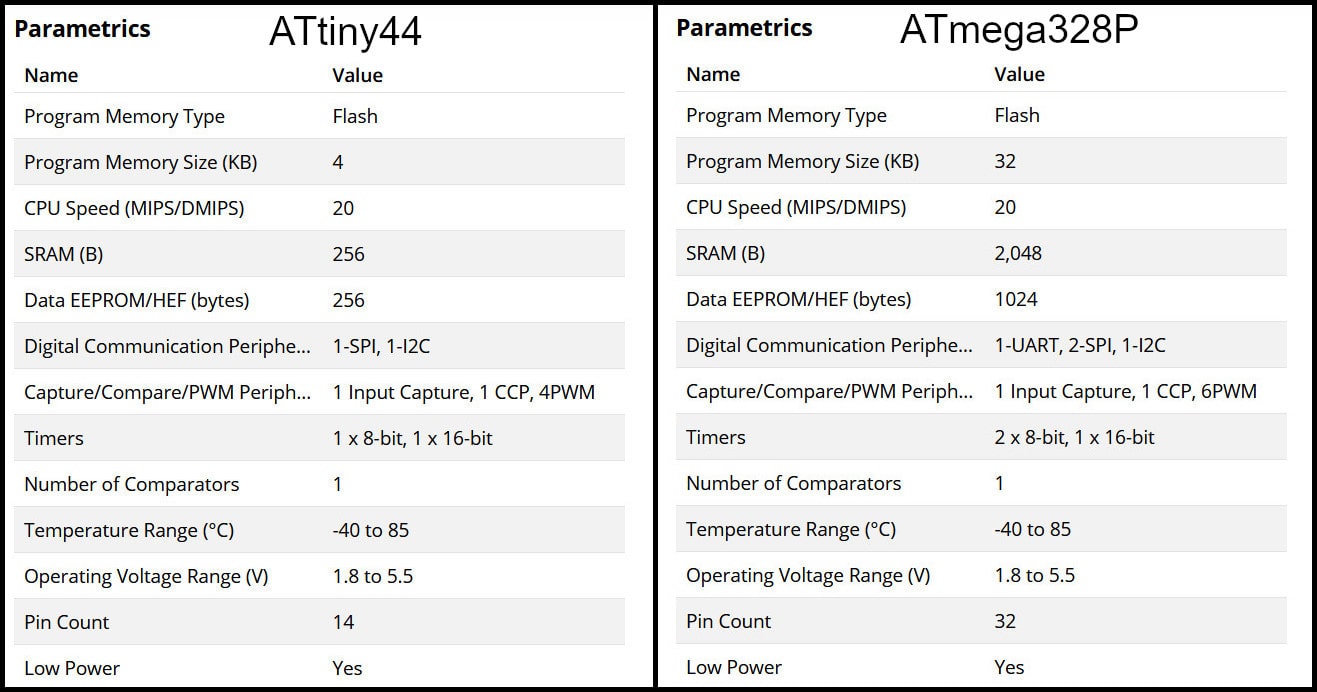
In this part we compared between two AVR families, ATtiny44 from tinyAVR family and ATmega328P from megaAVR family. For ATtiny44 we used AVR-dude and FabTinyISP programmer and for ATmega328P we used Arduino UNO board.
Feature Comparison:
The table below compares bwteen the two MCUs. “tinyAVR microcontrollers (MCUs) are optimized for applications that require performance, power efficiency and ease of use in a small package”, where “megaAVR microcontrollers (MCUs) are the ideal choice for designs that need some extra muscle. For applications requiring large amounts of code.” Source
Programming ATtiny44 using avr-dude
Write the program in C language using Notepad++ text editor. In the Makefile, define settings like programmer, target MCU, clock rate and lfuse. Using “make” command, build the hex file to be uploaded to target MCU. Connect the FabTinyISP prorammer to USB and ISP cable between programmer and target board. Using the command defined in Makefile “make program-avr-fuses”, program the lfuse to target MCU. Using the command defined in Makefile “make program-avr”, upload the hex file to target MCU.
Or following this guide to use it with Arduino IDE.
Using C and avr-dude:
#include <avr/io.h>
#include <util/delay.h>

int main()
{
    DDRB |= (1 << PB0);
    while(1){
        PORTB |= (1 << PB0);
        _delay_ms(500);
        PORTB &= ~(1 << PB0);
        _delay_ms(500);
    }
}
Using Arduio IDE:
void setup() {
  // put your setup code here, to run once:
  pinMode(8, OUTPUT); //PB0
}

void loop() {
  // put your main code here, to run repeatedly:
  digitalWrite(8, HIGH);
  delay(500);
  digitalWrite(8, LOW);
  delay(500);
}
avr-dude Vs. Arduino
Programming in C enables users to have more control and optimized execution. The code written in C occupies less memory than the code written in Arduino. Also, code written in C executes faster. Kepe in mind to program in C, the MCU should not have a bootloader burnt to it, which saves the flash memory needed for the bootloader.
The follwing codes blink a LED on pin PB0 in ATmega328P MCU. The first code using C language and avr-dude and the second using Arduion IDE.
And you can see below that after compiling on blinking code:
Using C code:
Sketch uses 104 bytes (2%) of program storage space. Maximum is 4096 bytes.
Global variables use 0 bytes (0%) of dynamic memory, leaving 256 bytes for local variables. Maximum is 256 bytes.
Using C++ code:
Sketch uses 804 bytes (19%) of program storage space. Maximum is 4096 bytes.
Global variables use 9 bytes (3%) of dynamic memory, leaving 247 bytes for local variables. Maximum is 256 bytes.
Individual assignments:
Objectives:
- Read a microcontroller data sheet.
- program your board to do something, with as many different programming languages and programming environments as possible.
DataSheet:
From the Microchip, I read the summary datasheet.
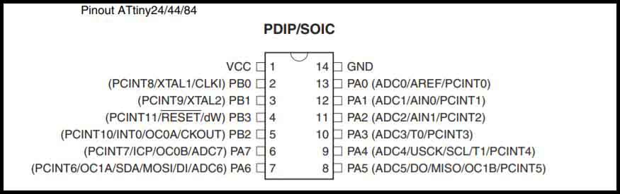
Pins layout:
-
VCC: Supply voltage.
-
GND: Ground.
-
Port B (PB3:PB0):
Port B is a 4-bit bi-directional I/O port with internal pull-up resistors (selected for each bit). The Port B output buffers have symmetrical drive characteristics with both high sink and source capability except PB3 which has the RESET capability. -
RESET:
Reset input. A low level on this pin for longer than the minimum pulse length will generate a reset, even if the clock is not running and provided the reset pin has not been disabled. The reset pin can also be used as a (weak) I/O pin. -
Port A (PA7:PA0):
Port A is a 8-bit bi-directional I/O port with internal pull-up resistors (selected for each bit). The Port A output buffers have symmetrical drive characteristics with both high sink and source capability. As inputs, Port A pins that are externally pulled low will source current if the pull-up resistors are activated. The Port A pins are tri-stated when a reset condition becomes active, even if the clock is not running.
Port A has alternate functions as analog inputs for the ADC, analog comparator, timer/counter, SPI and pin change interrupt.
Define Registers
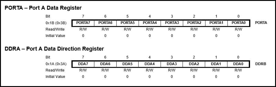
Port x Data Direction Register (DDRx):
It is to define the ports’ pins as input and/or outputs, like :
DDRA = 0b00001111; // where the ports PA0, PA1 ,PA2, and PA3 are outputs and the rest are inputs.
DDRA = 0x0F; //  or we can write it as a hex number 0x0F
Or define a single port:
DDRA |= ( 1 >> DDA3); // PortA3 is output
DDRA &= ~( 1>> DDA7); // PortA7 is inputs
Port x Data Register (PORTx):
The PORTxn bits in the PORTx register have two functions. They can control the output state of a pin and the setup of an input pin.
As an Output:
If a ‘1’ is written to the bit when the pin is configured as an output pin, the port pin is driven high. If a ‘0’ is written to the bit when the pin is configured as an output pin, the port pin is driven low.
As an Input:
If a ‘1’ is written to the bit when the pin is configured as an input pin, the pull-up resistor is activated. If a ‘0’ is written to the bit when the pin is configured as an input pin, the port pin is tri-stated.
DDRA  = 0x0F;        //lower pins output, higher pins input
PORTA = 0xF0;        //output pins set to 0, input pins enable pull-ups
Port x Input Pins (PINx):
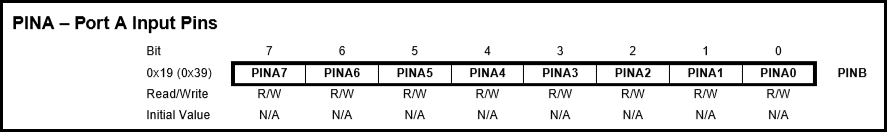
The PINxn bits in the PINx register are used to read data from port pin. When the pin is configured as a digital input (in the DDRx register), and the pull-up is enabled (in the PORTx register) the bit will indicate the state of the signal at the pin (high or low).
Note: If a port is made an output, then reading the PINx register will give you data that has been written to the port pins.
As a Tri-State Input: When the PORTx register disables the pull-up resistor the input will be tri-stated, leaving the pin left floating. When left in this state, even a small static charge present on surrounding objects can change the logic state of the pin. If you try to read the corresponding bit in the pin register, its state cannot be predicted.
Preparing Arduino:
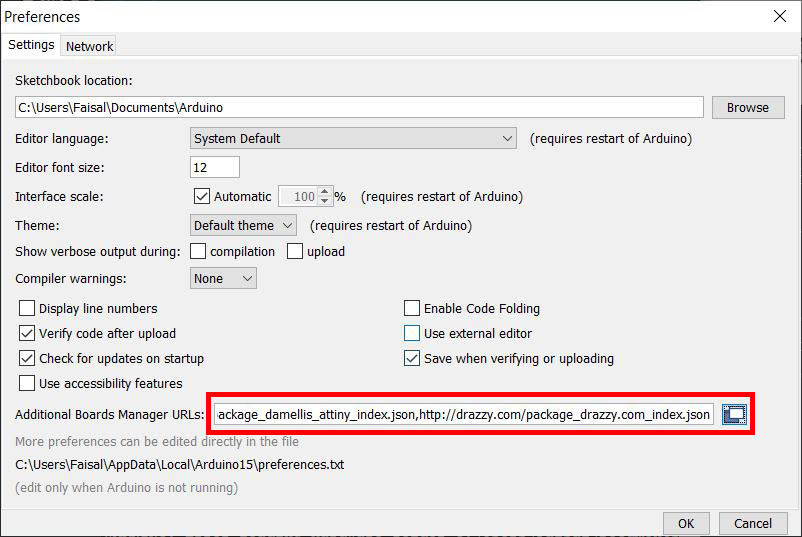
To download the repository, copy the next Link to Preferences under the File tab, and paste it next to Additinal Boards Manager URLs:.
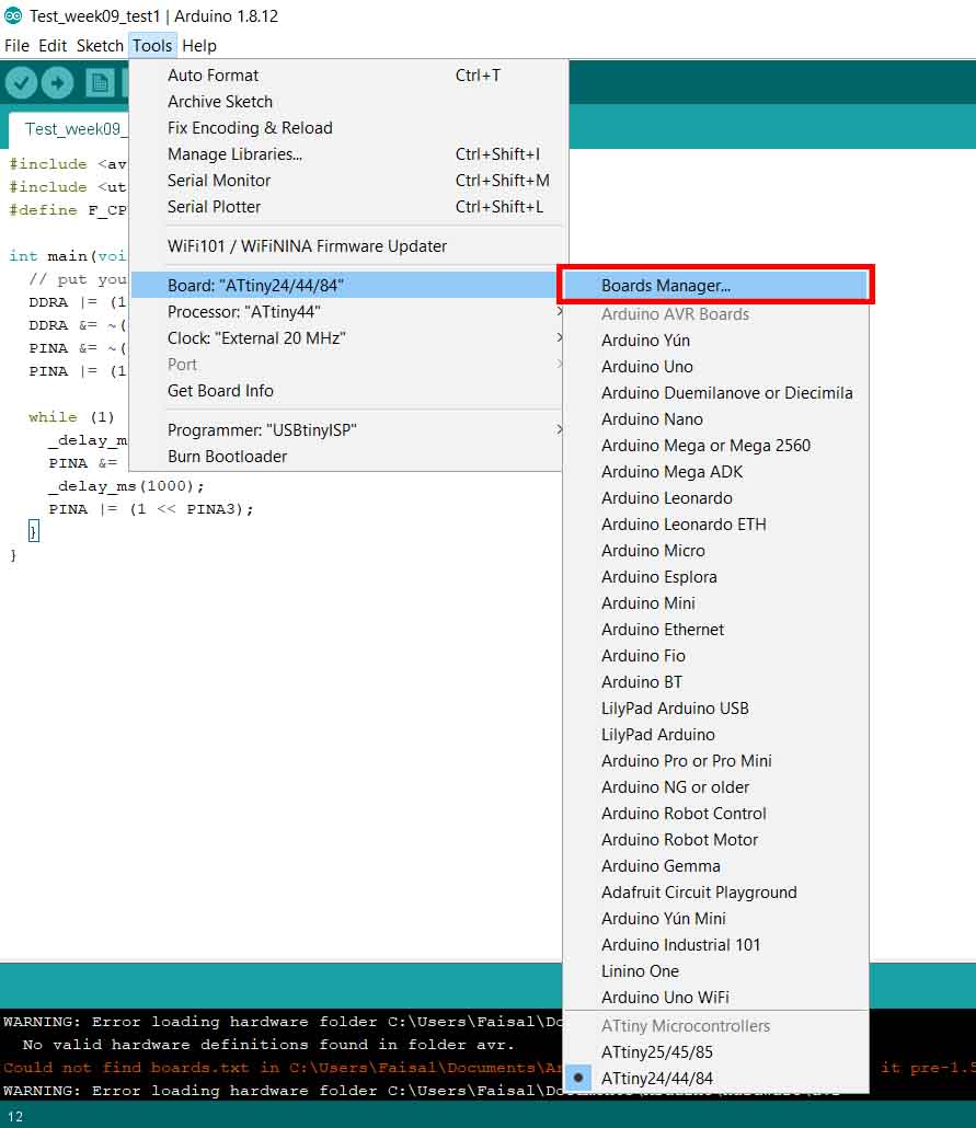
Then open Boards Manager.
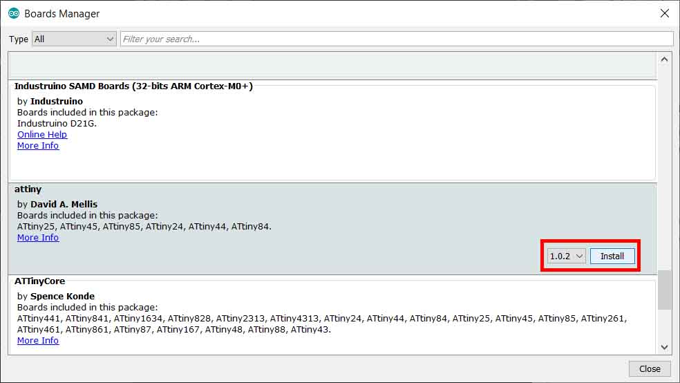
Then install ATtiny.
Restart Arduino, then go to Tools Boards and choose ATtiny24/44/84, then select the Processor ATtiny44, Clock External 20MHz.
The programmer can the USBtinyISP that we made week05, or Arduino Uno.
When connecting the ATtiny44, use Burn Bootloader under the Tools tab.
Example Codes:
Blinking LED:
Program Code in C.
// Blinking LED in C
// Created By Faisal
// 21-March-2020

#include <avr/io.h>
#include <util/delay.h>
#define F_CPU 20000000UL

int main(void) {
  // put your setup code here, to run once:
  DDRA |= (1 << DDA3); // Define pin A3 LED as an output
  DDRA &= ~(1 << DDA7); // Define pin A7 Button as an input
  PINA &= ~(1 << PINA7); // 0 to use internal pull-up resistor to pin A7, 1 to use external
  PINA |= (1 << PINA3);// Define value of LED as 1

  while (1) {
    _delay_ms(500);
    PINA &= ~(1 << PINA3);
    _delay_ms(1000);
    PINA |= (1 << PINA3);
  }
}
When compiling it used program storage space, and Global variables.
Sketch uses 104 bytes (2%) of program storage space. Maximum is 4096 bytes.
Global variables use 0 bytes (0%) of dynamic memory, leaving 256 bytes for local variables. Maximum is 256 bytes.
Program Code in C/C++.
// Blinking LED in C++
// Created By Faisal
// 21-March-2020

const int led = 3;
const int button = 7;

void setup() {
  // put your setup code here, to run once:
  pinMode (led, OUTPUT);
  pinMode (button, INPUT);
}

void loop() {
  // put your main code here, to run repeatedly:
  delay(500);
  digitalWrite(led, HIGH);
  delay(1000);
  digitalWrite(led, LOW);
}
When compiling it used program storage space, and Global variables.
Sketch uses 804 bytes (19%) of program storage space. Maximum is 4096 bytes.
Global variables use 9 bytes (3%) of dynamic memory, leaving 247 bytes for local variables. Maximum is 256 bytes.
Conclusion:
When programming with C++ it will take more program storage space, as well as global variables.
Pushbutton Program in C++:
// Switch LED by Pushbutton in C and C++
// Recreated By Faisal
// 22-March-2020

#include <avr/io.h>

const int led = 3;
const int button = 7;
int PBval = 0; // reading pushbutton pin status
int debounce = 300;
int LEDval = HIGH;

void setup() {
  // put your setup code here, to run once:
  pinMode (led, OUTPUT);
  pinMode (button, INPUT);
  PINA |= (1 << PINA7); // 1 to use internal pull-up resitor to pin A7, 0 to use external
  digitalWrite(led, LEDval);
}

void loop() {
  // put your main code here, to run repeatedly:
  PBval = digitalRead (button);
  if (PBval == LOW) {
    delay(debounce);
    LEDval = !LEDval;
    digitalWrite(led, LEDval);
  }
}
When compiling it used program storage space, and Global variables.
Sketch uses 906 bytes (22%) of program storage space. Maximum is 4096 bytes.
Global variables use 11 bytes (4%) of dynamic memory, leaving 245 bytes for local variables. Maximum is 256 bytes.
Recreate Echo Program in C++:
Part one:
With serial communication.
// Echo in C and C++
// Recreated By Faisal
// 22-March-2020

#include <avr/io.h>
#include <SoftwareSerial.h>

const int rxPin = 0;
const int txPin = 1;
const int led = 3;  // Make sure that is the program is running
// const int button = 7; //Disabled for dynamic memory
const int max_buffer = 25; // Buffer index size
boolean newData = false; // Check new data

// Prepare Serila with Tx, Rx Pins
SoftwareSerial mySerial(rxPin, txPin); // RX, TX

void setup() {
  pinMode (led, OUTPUT);
  // pinMode (button, INPUT); //Disabled for dynamic memory
  // define pin modes for tx, rx:
  pinMode(rxPin, INPUT);
  pinMode(txPin, OUTPUT);
  // Initialize Serial
  mySerial.begin(115200);
  delay(3000); // To see the message when open the monitor via FTDI cable
  mySerial.println("<Echo is ready>");
  digitalWrite(led, HIGH);
}

void loop() {
  // Static variables persist beyond the function call,
  // preserving their data between function calls.
  // Unlike local variables that get created and
  // destroyed every time a function is called
  static char chr;
  static char buffer[max_buffer] = {0};
  static int index;

  // Check if serial is ready, with new data:
  if (mySerial.available() > 0) {
    // read the incoming byte:
    delay(50);
    chr = mySerial.read();
    newData = true;
  }
  // Print out the new data:
  if (newData == true) {
    buffer[index] = chr;
    delay(8.5);
    // say what you got:
    mySerial.println(buffer);
    ++index;
    newData = false;
  }
  // Reset the buffer for manage the memory
  if (index == 25) {
    index = 0;
    while (index <= 25) {
      buffer[index] = 0;
      delay(8.5);
      ++index;
    }
    index = 0;
  }

}
Part two:
Added Pushbutton to reset Buffer:
// Echo in C and C++
// Recreated By Faisal
// 22-March-2020

#include <avr/io.h>
#include <SoftwareSerial.h>

const int rxPin = 0;
const int txPin = 1;
const int led = 3;  // Make sure that is the program is running
const int button = 7; //Disabled for dynamic memory
int PBval = 0; // reading pushbutton pin status
const int debounce = 300;// debounce for pushbutton
const int max_buffer = 25; // Buffer index size
boolean newData = false; // Check new data

// Prepare Serila with Tx, Rx Pins
SoftwareSerial mySerial(rxPin, txPin); // RX, TX

void setup() {
  pinMode (led, OUTPUT);
  pinMode (button, INPUT);
  PINA |= (1 << PINA7); // 1 to use internal pull-up resitor to pin A7, 0 to use external

  // define pin modes for tx, rx:
  pinMode(rxPin, INPUT);
  pinMode(txPin, OUTPUT);
  // Initialize Serial
  mySerial.begin(115200);
  delay(3000); // To see the message when open the monitor via FTDI cable
  mySerial.println("<Echo is ready>");
  digitalWrite(led, LOW);
}

void loop() {
  // Static variables persist beyond the function call,
  // preserving their data between function calls.
  // Unlike local variables that get created and
  // destroyed every time a function is called
  static char chr;
  static char buffer[max_buffer] = {0};
  static int index;
  PBval = digitalRead (button);
  if (PBval == LOW) {
    delay(debounce);
    digitalWrite(led, HIGH);
    mySerial.println("Clear Buffer");
    index = 0;
    while (index <= 25) {
      buffer[index] = 0;
      delay(8.5);
      ++index;
    }
    index = 0;
    digitalWrite(led, LOW);
  }
  // Check if serial is ready, with new data:
  if (mySerial.available() > 0) {
    // read the incoming byte:
    delay(50);
    chr = mySerial.read();
    newData = true;
  }
  // Print out the new data:
  if (newData == true) {
    buffer[index] = chr;
    delay(8.5);
    // say what you got:
    mySerial.println(buffer);
    ++index;
    newData = false;
  }
  // Reset the buffer for manage the memory
  if (index == 25) {
    index = 0;
    while (index <= 25) {
      buffer[index] = 0;
      delay(8.5);
      ++index;
    }
    index = 0;
  }

}
Compare the Echo programed in C, and Echo programed in C++:
Program in C++:
Without reset buffer button:
Sketch uses 2658 bytes (64%) of program storage space. Maximum is 4096 bytes.
Global variables use 187 bytes (73%) of dynamic memory, leaving 69 bytes for local variables. Maximum is 256 bytes.
With reset buffer button:
Sketch uses 2450 bytes (59%) of program storage space. Maximum is 4096 bytes.
Global variables use 175 bytes (68%) of dynamic memory, leaving 81 bytes for local variables. Maximum is 256 bytes.
Sketch uses 664 bytes (16%) of program storage space. Maximum is 4096 bytes.
Global variables use 64 bytes (25%) of dynamic memory, leaving 192 bytes for local variables. Maximum is 256 bytes.
Conclusion:
In C programing, much less size used in the storage space, and Global variables, but it takes more lines to program and more complex to program, the exact opposite of programming with C++.
Three Hero shoot:
Switch LED state with push Button:
The LED with switch it values when the pushbutton is pressed.
Hello World part 1:
Using FTDI, we can see the keyboard input send to the ATtiny44, then it will send it back to the monitor of the Arduino IDE.
Hello World part 2:
Using FTDI, we can see the keyboard input send to the ATtiny44, then it will send it back to the monitor of the Arduino IDE, and rest the buffer using the pushbutton.