11. Applications and implications
Project Zoetrope:
What will do?
Tl;dr: Put a special 3d model on a rotary DC motor, and direct a strobe of light on a certain frequency to give the illusion of moving slowly, when in reality it is rotating in a high speed.
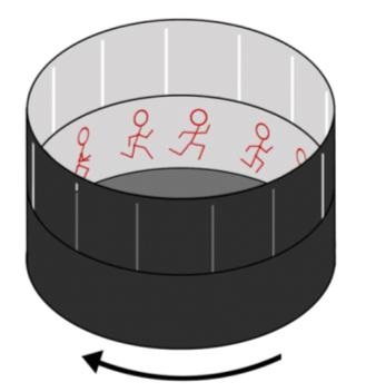
A traditional zoetrope is a device that produces the illusion of motion from a rapid succession of static pictures. The zoetrope consists of a cylinder with slits cut vertically in the sides. On the inner surface of the cylinder is a band with images from a set of sequenced pictures.
But instead of the slits cut vertically in the sides of a cylinder, it will be replaced by a LED strobe light on a certain frequency that do the same job.
Who’s done what beforehand?
-
Simon Stampfer (1833)
Simon Stampfer, one of the inventors of the phenakistiscope animation disc (or “stroboscope discs” as he called them), suggested in July 1833 in a pamphlet that the sequence of images for the stroboscopic animation could be placed on either a disc, a cylinder or a looped strip of paper or canvas stretched around two parallel rollers. Stampfer chose to publish his invention in the shape of a disc. -
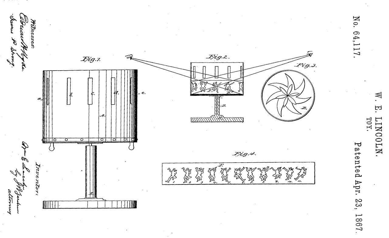
**William Ensign Lincoln & Milton Bradley’s Zoetrope (1865–1867)
William Ensign Lincoln invented the definitive zoetrope in 1865 at Brown University, Providence, Rhode Island. Lincoln’s patented version had the viewing slits on a level above the pictures, which allowed the use of easily replaceable strips of images. It also had an illustrated paper disc on the base, which was not always exploited on the commercially produced versions. Lincoln sent a model to color lithographers and board game manufacturers Milton Bradley and Co..
- John Edmark’s Zoetrope (Blooms)
Blooms are 3D printed sculptures designed to animate when spun under a strobe light. Unlike a 3D zoetrope, which animates a sequence of small changes to objects, a bloom animates as a single self-contained sculpture. The bloom’s animation effect is achieved by progressive rotations of the golden ratio, phi (ϕ), the same ratio that nature employs to generate the spiral patterns we see in pinecones and sunflowers. The rotational speed and strobe rate of the bloom are synchronized so that one flash occurs every time the bloom turns 137.5º (the angular version of phi). Each bloom’s particular form and behavior is determined by a unique parametric seed I call a phi-nome (/fī nōm/).
Blooms: Strobe Animated Sculptures Invented by John Edmark from John Edmark on Vimeo.
- From fabacademy 2017 Juliana Henno
Juliana Henno has work on it before, her idea of the 3D Zoetrope is that she could build a motorized platform that could be adjusted in relation of the blinking LED. The strobe effect generated by the blinking LEDs will cause an illusion of a camera shutter in which the flickering image(s) on the platform will give an idea of being in a constant motion without any breaks or intervals.
In order to amplify the contrast between darkness and light, the platform was projected to be enclosed inside of a container. This way, the light would be blocked from outside and the only brightness inside would be provided by the Strobe blinking effect.
Final Project from Juliana Henno on Vimeo.
What will you design?
Part 1: the zoetrope itself
It will be 3D printed, by using Blender 2.79 and Sverchok addon that can make parametric shapes.
And it already done in the final project step by step.
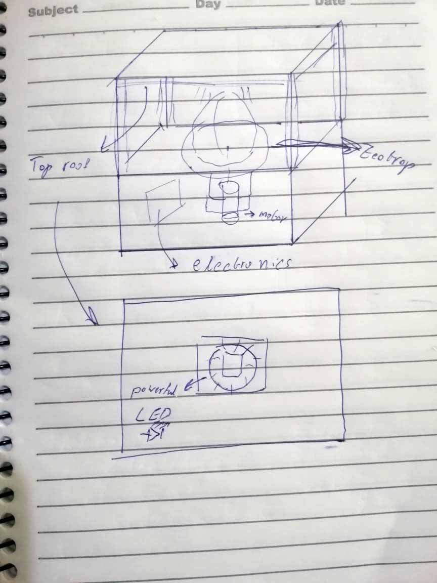
Part 2: The housing case:
- Under the roof, I will mount the LED to give focus the light on the zoetrope.
- The zoetrope will be showcased.
- DC motor will be mounted under the zoetrope.
- The control circuit will be mounted in the box under the zoetrope.
Part 3: the control circuit
- To control the DC motor, by reading the speed of the motor to get the right speed.
- To control the LED to give light strobes at a certain frequency.
- Maybe add display; LCD or OLED.
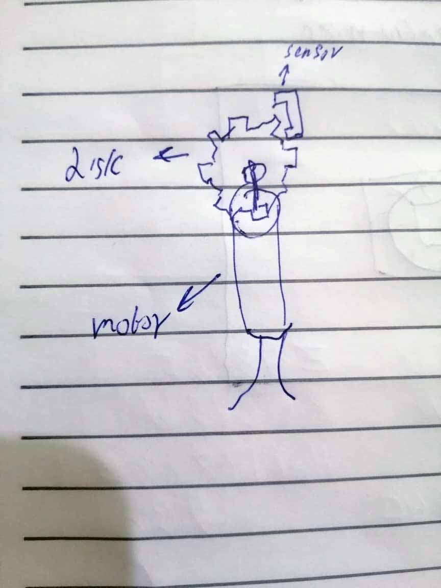
Part 4: Input to read for speed of the motor:
To read the speed of the motor in RPM, by adding a encoder disk on the shaft of the motor.
What materials and components will be used?
3D printed parts:
- Zoetrope.
- Mount for the motor.
- Encoder disk.
- Mount for Speed encoder input.
- Mount for the LED.
Laser cut parts:
- The showcase(mdf) 8mm thickness.
- Acrylic enclosure for the showcase (maybe).
PCB:
- The control circuit.
- The output circuits for the motor and LED.
- Input circuit for reading the RPM of the DC motor.
Bill of Materials (BOM):
Electronics:
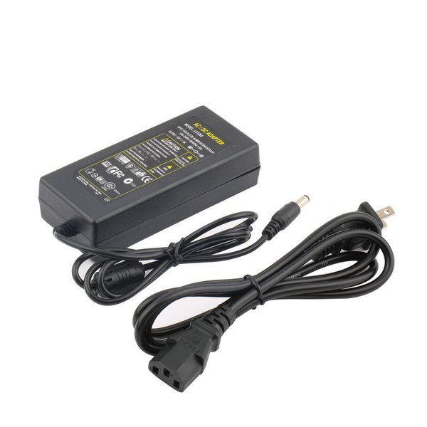
- Adapter 12V 5A Power supply AC/DC for the system.
- DC motor.
Output devices:
Control the DC motor:
| Part name | Footprint | Quantity |
|---|---|---|
| PMIC_H-BRIDGE_A4953_PAD | SOIC8 | 1 |
| VR_REGULATOR-SOT23 | SOT23 | 1 |
| CONN_02X2-PINHEAD-SMD | 2X02SMD | 3 |
| CAP_UNPOLARIZED 1μF | C1206FAB | 1 |
| CAP_UNPOLARIZED 10μF | C1206FAB | 1 |
| Resistor 1k | R1206FAB | 1 |
| LED | LED1206FAB | 1 |
Control the LED:
| Part name | Footprint | Quantity |
|---|---|---|
| P-CHANNEL MOSFET 20V 24A NDP6020P | TO-220 | 1 |
| LOHAS 100W LED Chip Cool White Bulb High Power Energy | ----- | 1 |
| Aluminium Heatsink Cooling Fan | ----- | 1 |
Input devices:
For reading the RPM of the motor:
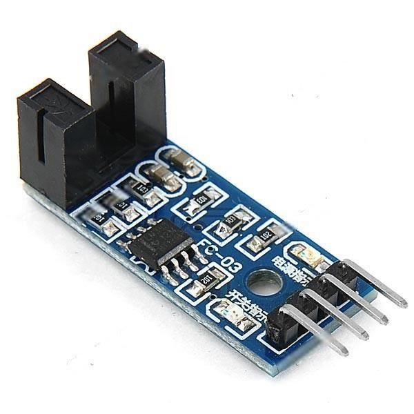
- Speed encoder sensor module, that gives pulse signals.
or
- Hall Effect Sensor Single Axis, data sheet.

How much will they cost?
| Part name | Quantity | Total Price |
|---|---|---|
| Adapter 12V 5A Power supply AC/DC | 1 | 10 JD |
| Speed encoder sensor module | 1 | 4.5 JD |
| P-CHANNEL MOSFET 20V 24A NDP6020P | 1 | 2 JD |
| Aluminium Heatsink Cooling Fan | 1 | 14 JD |
| MDF wood 8mm thickness | 1 | 6 JD |
What questions need to be answered?
- What input device will I will use?
- What microcontroller will I will make?, the code integration if there are conflict using
Timers?; the strobe program is using timer, as well as the reading of the motor rotational speed.
How will it be evaluated?
By seeing the smooth motion in person and in video recording by a camera, because the video camera needs a different strobing frequency.