3. Computer Aided design
Download Files:
Blender:
1- Set up blender:
A- Get addon Blender Shortcut VUr from github, to display mouse and keyboard input on screen.
Blender display mouse and keyboard input tutorial
B- Set the units to Metric, Imperial or None, then select the desired length.
C- You should save the defaults to not repeat it every time you open Blender as shown in the picture below.
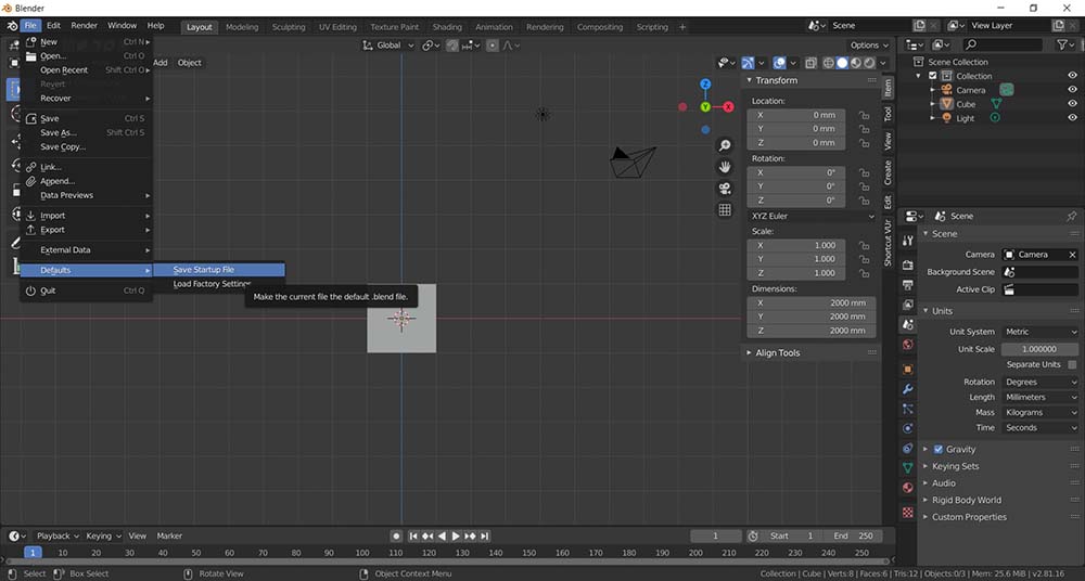
File ----> defaults ----> Save startup File
2- Making similar tutorials to FreeCad:
Snaps:
There are multiple ways to snap objects, you can snap to edges, vertices and faces of the polygons.
As well as we can choose where to snap; Center, closest, median and active.
Extrude:
There are multiple ways to extrude in Blender; extrude region most used, extrude along normals, extrude individual or extrude to cursor.
Revolve:
To spin a curve in Blender, where i made a random curve by putting random points.
Loft:
A tool to make a surfaces line or surfaces.
Sweep:
Sweep a closed curve around another curve.
Constructive solid geometry CSG:
In Blender it have similar tools called Boolean, where we can join, intersects or union between two objects, the one has the modifier will be affected.
Fillet chamfer:
Add a bevel to the model.
Offset:
Here it is called solidfy.
Hierarchy:
Constrain where the objects with this modifier, will change according to target object from location, rotation and scale.
Alignment:
It is an addon, where you have it under the item tab, where you can align location, rotation and scale.
Animation:
By click on the record button, when any change we make from location, rotation and scale, it will be saved in the frame, and change by default linearly according to the changes in the next frames, even if you changed any number of frames later.
3- Making a 3D model:
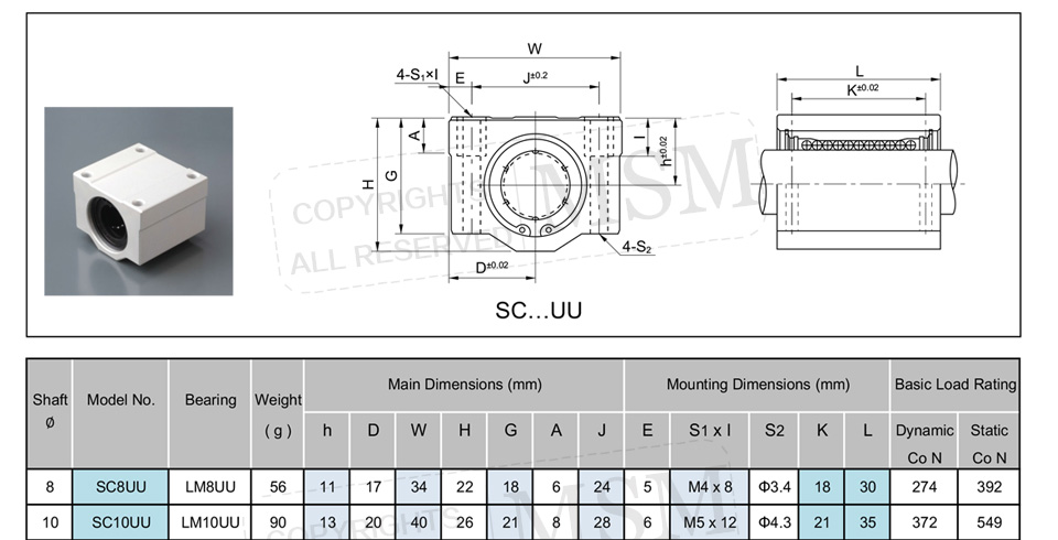
I pulled a datasheet of a linear bearing and model it.
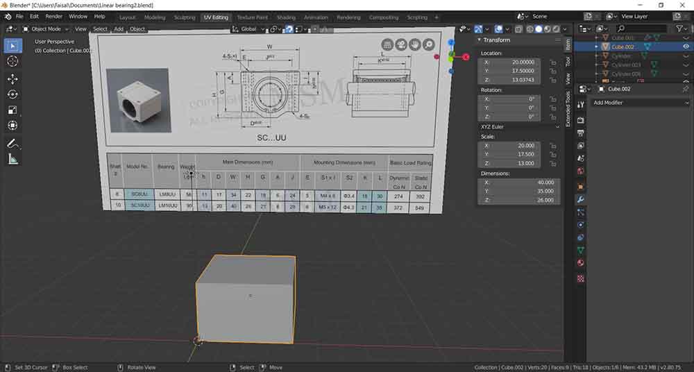
Step1:
Make a cube and adjust the dimensions according to the datasheet.
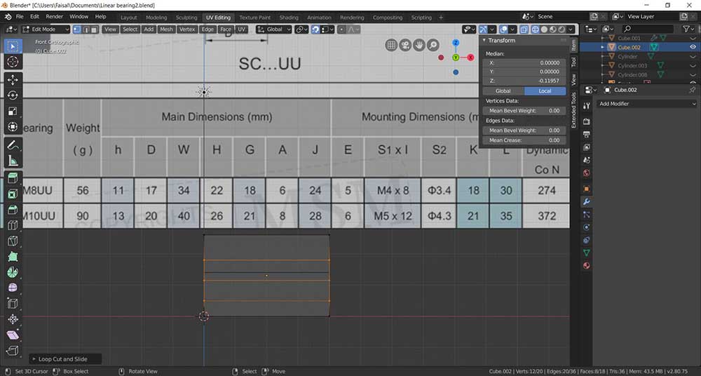
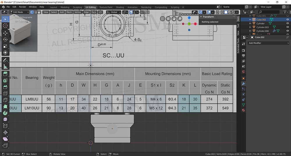
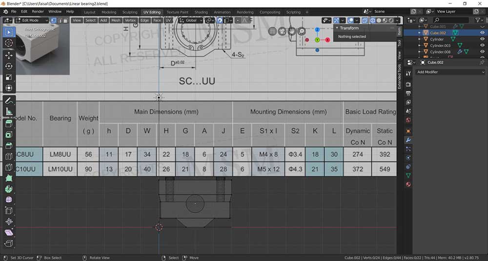
Step2:
Using Cut loop tool, I have made three cuts, then make a 3 planes to reference the G, I, and H.
Step3:
Made 3 cylinders to match the holes in the data sheet, then the top cylinders to their positions, then set their Point of origin to the model, then used the tool mirror to X and Y axis.
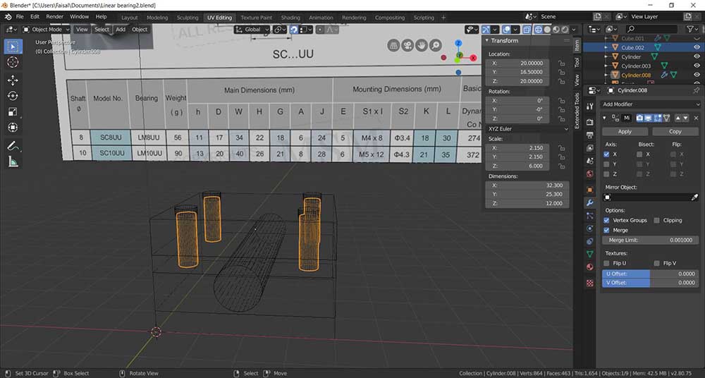
Step4:
Scaled the point in the X-axis to match the dimensions in the data sheet.
The results.
Step5:
By shortcut Ctrl+A, I have applied the Scale transformation to them model, to use the Bevel properly.
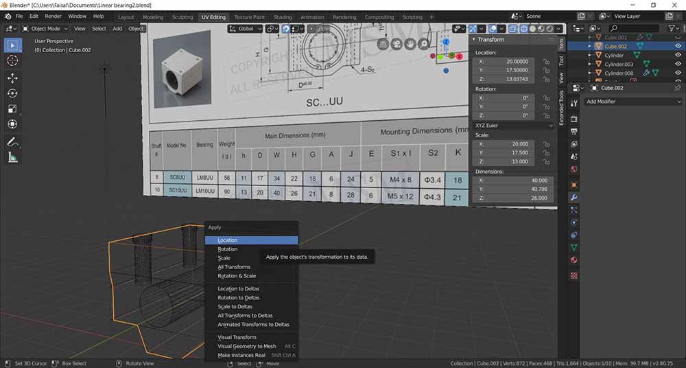
Select the edges then use the Bevel tool to have small rounded edges.
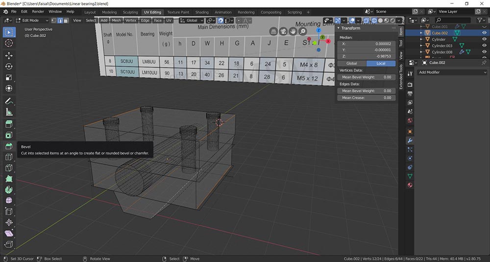
The results.
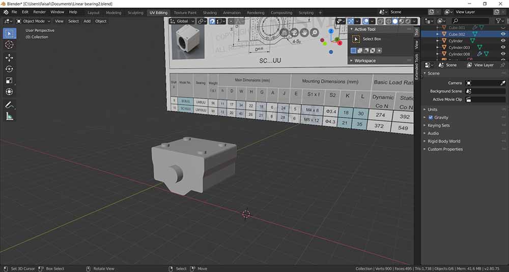
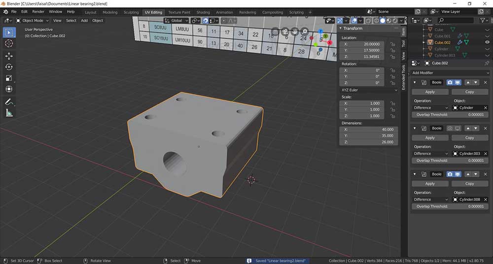
Step6:
Select the Linear Bearing model, then go to the modifier tab, then select Boolean and set the Operation to Difference and copied it 3 times.
Select the cylinders and we have our model.
Rhino:
Rhino is a 2D/3D design program, which you can do a simple modeling with fixed coordinates and dimensions, or parametric modeling based on algorithmic thinking that enables the expression of parameters and rules that, together, define, encode and clarify the relationship between design intent and design response.
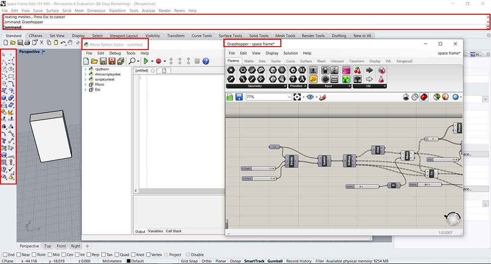
The creation tools we can use from Rhino are:
1- Command: Located on top, which you can enter the commands to create any 2D/3D objects by typing them.
2- Sidebar: Located on the left, which have the basic tools to also to create any 2D/3D objects.
3- Python Editor: You can run it from the command line EditphytonScript.
4- Grasshopper: You can run it from the command line Grasshopper, and it will prompts a new window with pre-programed algorithmic tools to generate a parametric model.
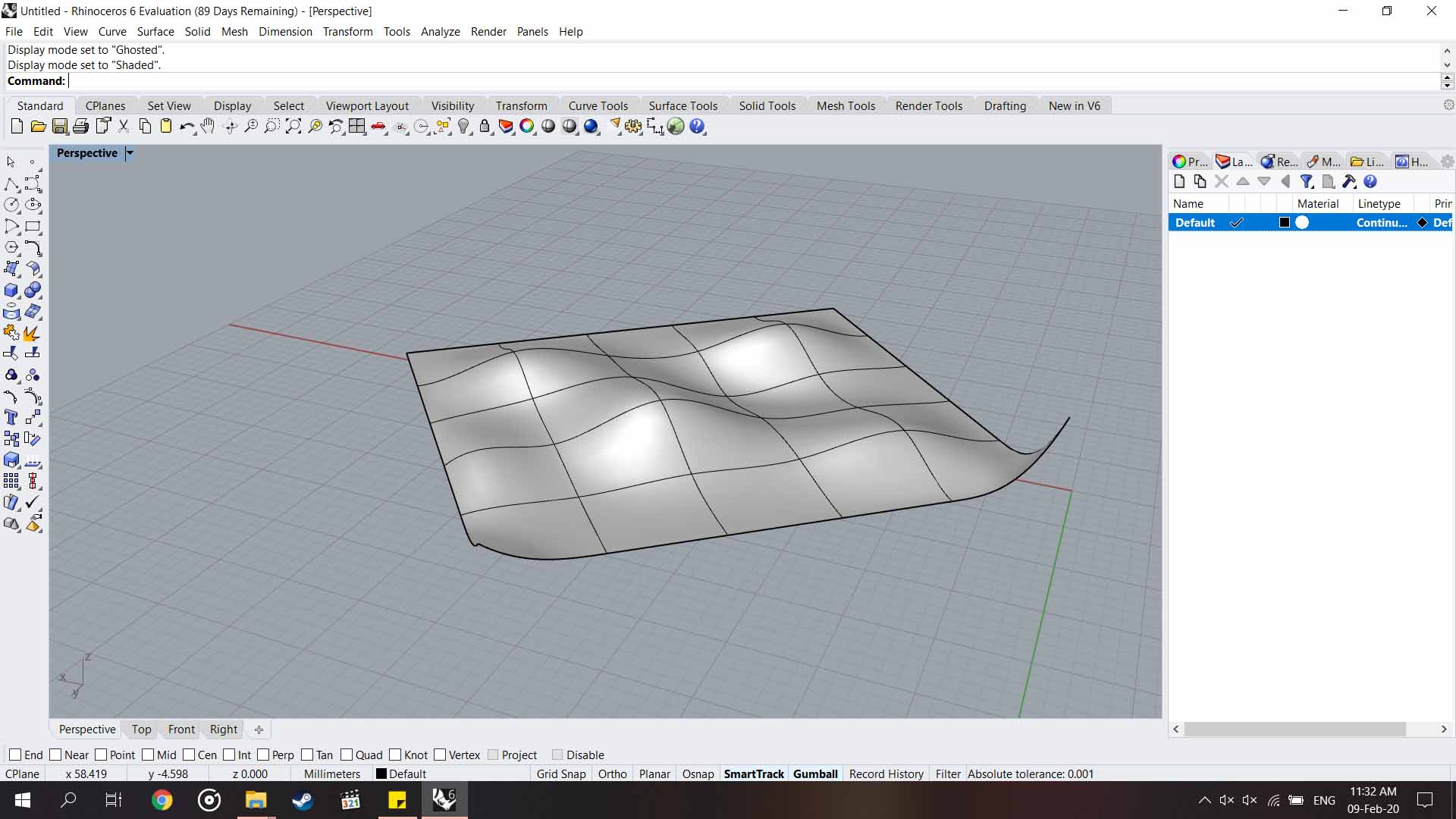
We made this week a Grasshopper code that enter a surface and convert to a spaceframe, by taking dividing the surface into multiple surfaces and take centroid of the sub surfaces as a new points, then moving them up in the Z-axis, then connect all the vertices/ points by lines, then sweep the lines/ edges with pipe shape, and generate spheres from the points locations as shown below.
1- We created random surface, with a subdivision code 5x5, with random height changes to its vertices.
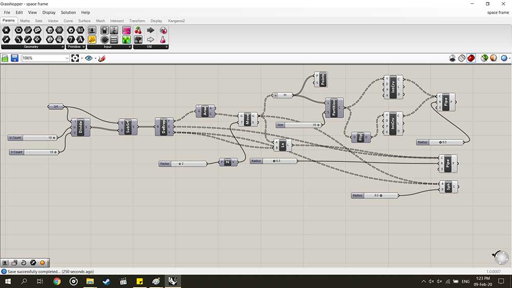
2- We created a program in Grasshopper that do the following:
A- First input is the Surface srf and re-divided it to UV input as a parameters, I have put 10x10, then put it into Isotrim.
B- Then we put the node Deconstruct Brep that Deconstruct a the part into its constituent parts, where the outputs are Faces, Edges, and Vertices.
C- We took the faces output and put it in Area node, where we have the center of each subsurface middle point, then offset them by Move node by 2, then put the output of the moved center points and vertices of the surface in a sph sphere node, with 0.5 radius.
D- We also took the offset center points and the vertices of the original surface, and connect them as line using ln node, and put them in a pipe node to give the shape of a pipe with 0.3 radius. As well as, the lines Edges of the surface.
E- We took the output moved vertices from C, and put it in the Partition List Adv node; where it convert it into a list into sub-lists by partition size, where put its value 10, then Interpolate the into two lists one of them is flipped using Flip node to give UV lines using the Interpolate node, the output lines is put into the pipe node to make them into pipes with same radius of the others 0.3.
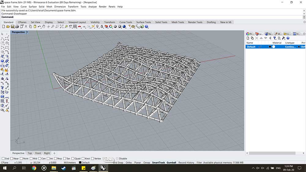
Output of Grasshopper program.
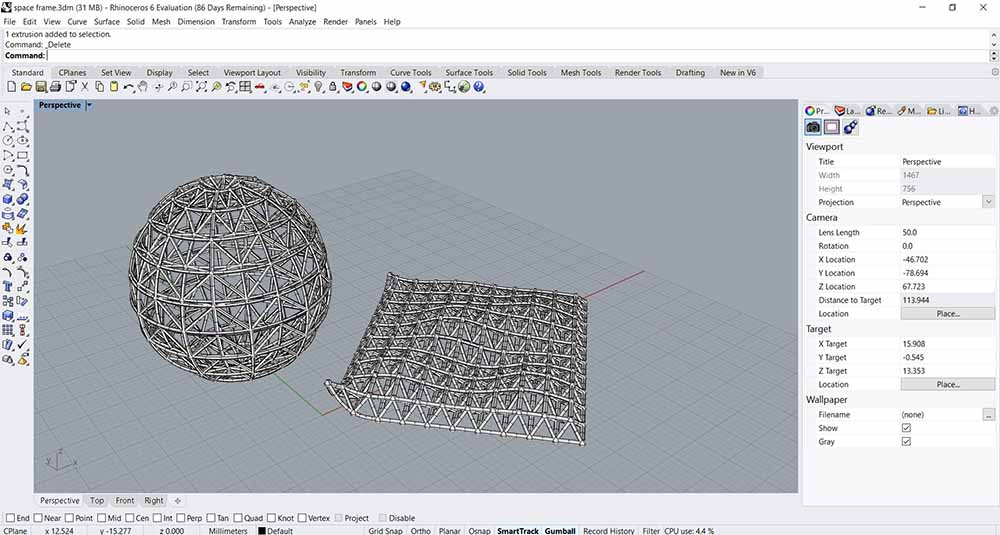
3- Or you can put new surface input for example a sphere, and we will get different output.
2D design:
I generally use Artcam to do vectors designs, however most the time I do them manually by tracing the images, and fix the vectors if there are errors in the curves and lines.
I sometime use Inkscape to trace bitmap, but the output is not always good.
And last I use photoshop to do renders/ mockups to see the final products.
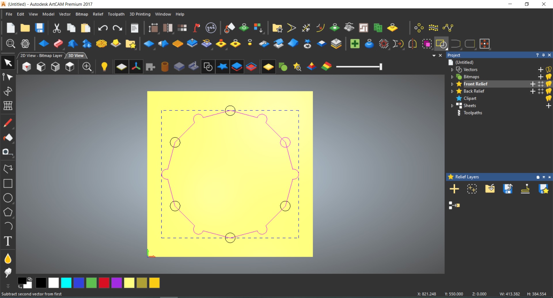
Make a vector design in ArtCam 2017:
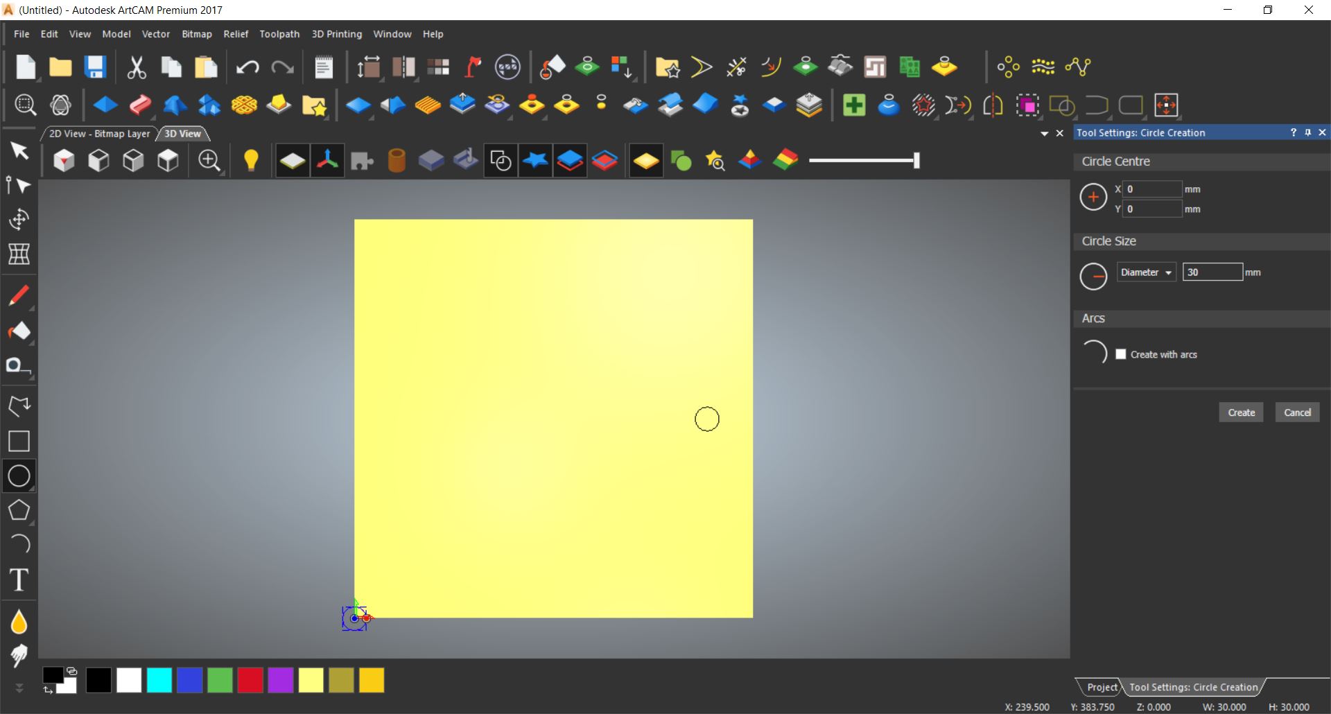
First of all I made a page with 500mm by 500mm, then I drew circle with 30mm diameter, and I put is on the right side.
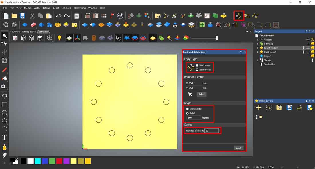
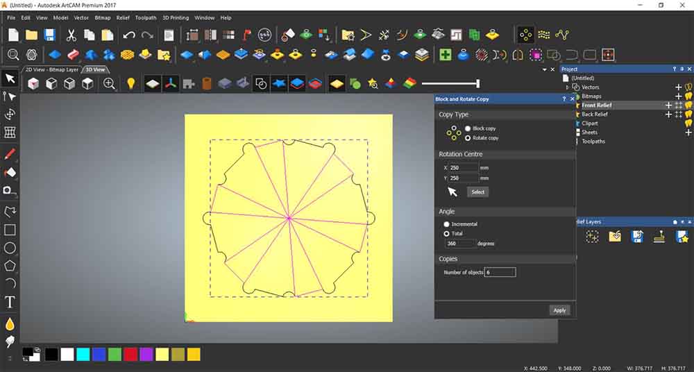
From Block and Rotate Copy, I set the center to the model, put full rotation 360 degrees and number of object is 12.
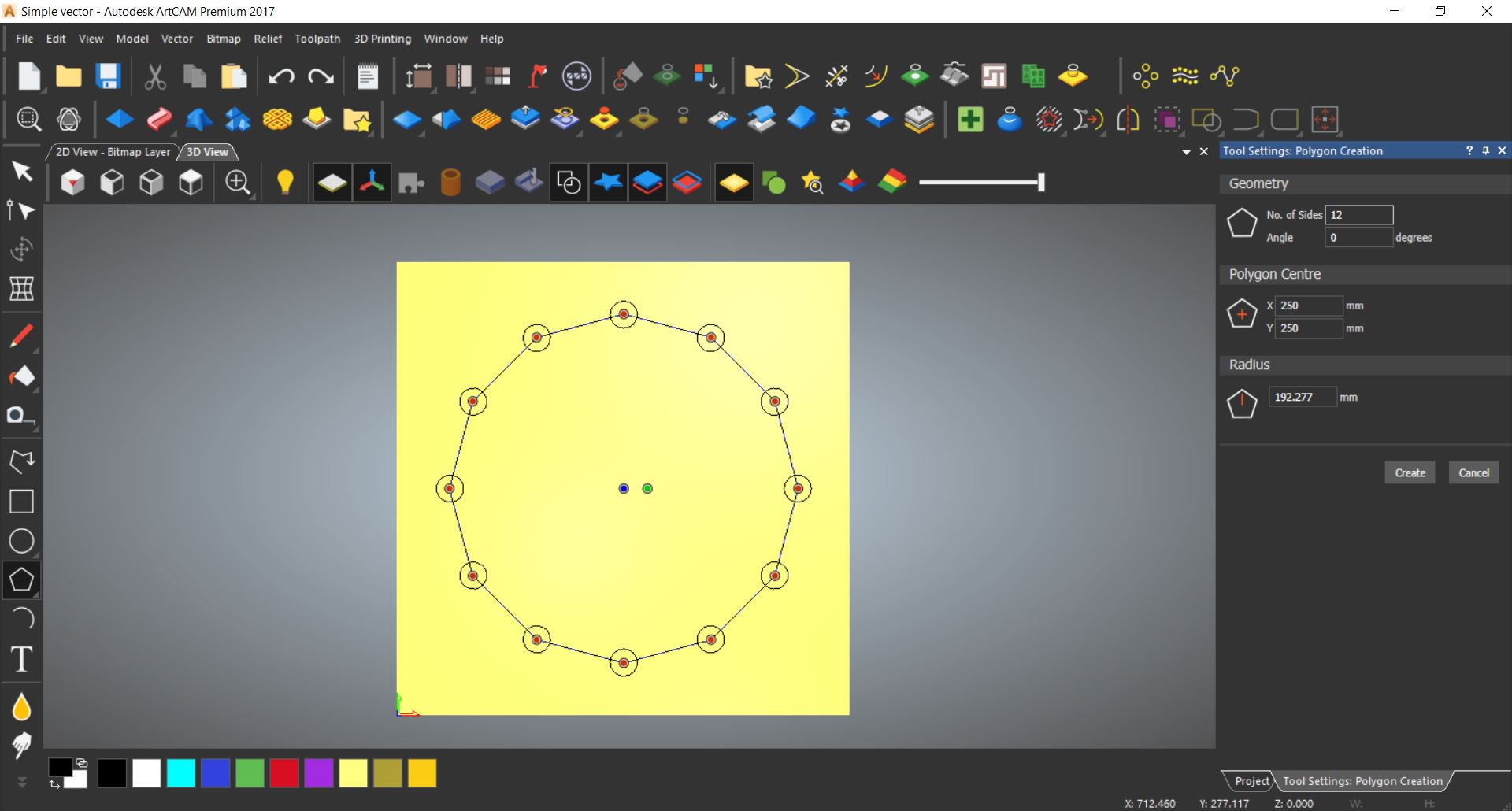
Then I made a polygon with 12 side, in the center
Then I weld/ merged the half of the circles to the polygon.
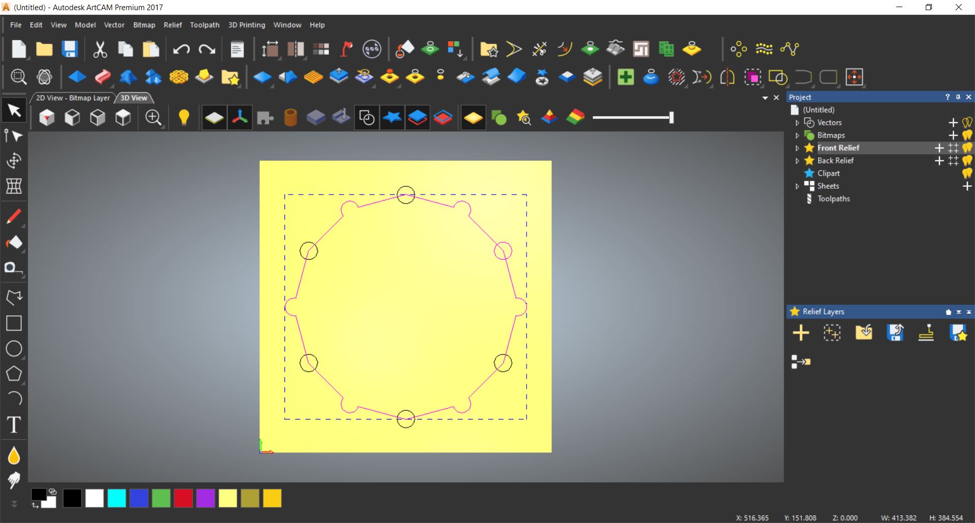
Then I subtracted the other half.
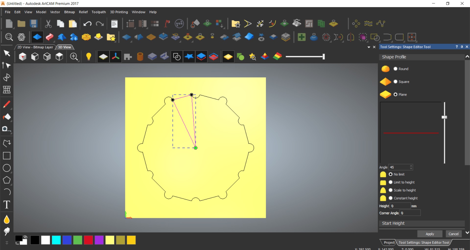
Then I drew triangle using polyline tool.
Then also made a copy rotation, and the number of objects is 6.
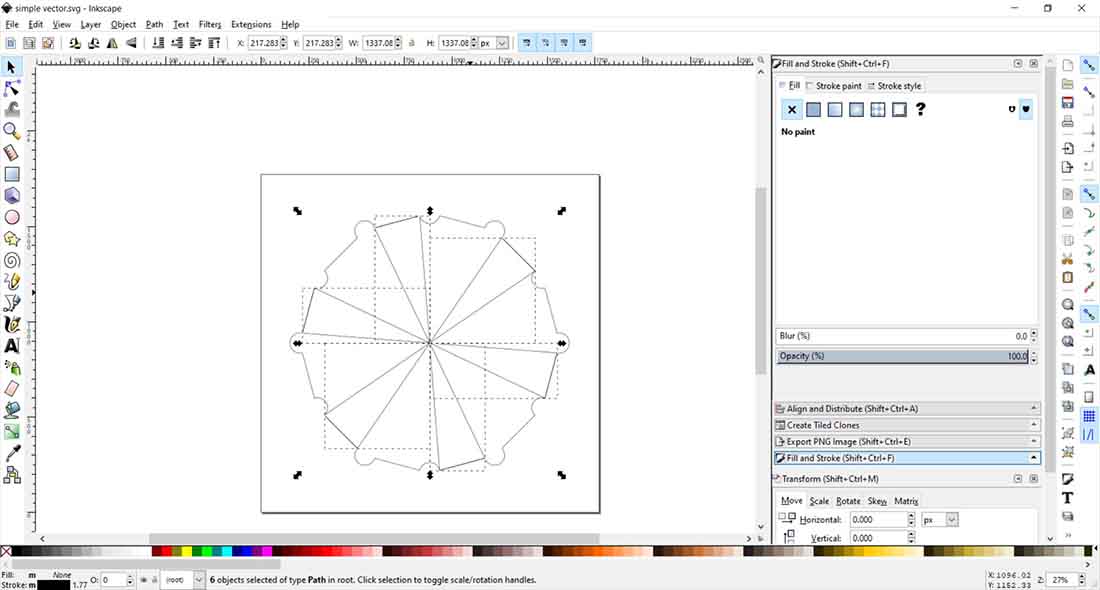
Then export it as SVG file, so I can open it in Inkscape.
Continue the design to Inkscape.
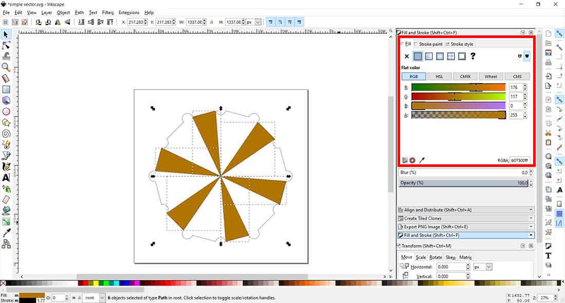
I open the file, then selected the triangles and change the fill color.
Changed the colors on RGB sliders.
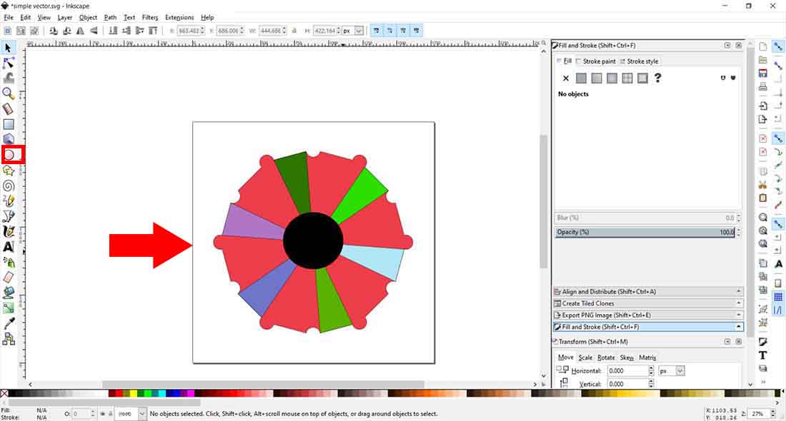
Change the polygon color, then added a circle around the middle of it.
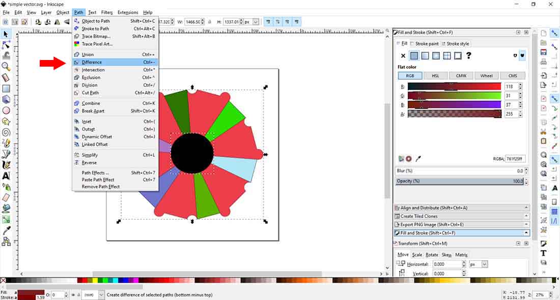
Then I selected the circle and the polygon, then from the Path tab I clicked on Difference to make a hole in the middle.
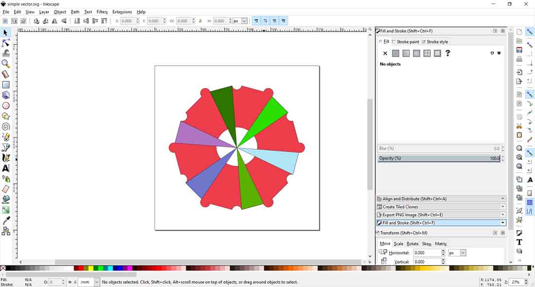
Here is the result.
Hero shoot:
Conclusion:
I used blender before as a hobby to make 3d models, I had some experience before, but it was a good experience for me to do the same things or closer to FreeCad, it gave me a new perspective.
I for the 2D designs, I have also experience because my line of work, and I am used to multiple programs to design vectors.
As for the Rhino’s Grasshopper, it was new experience to me, to do parametric designs, and not to redo the same job over and over again, after some researching, I have found that there is a similar extension for blender same as Grasshopper, and it is call Sverchok, that do almost the same parametric node designs and it is opensource.