5. Electronics production
Files used:
Group Assignment:
Objective:
To characterize the design rules for your PCB production process
Assignment requirements:
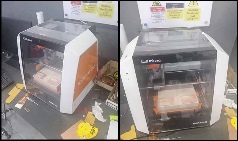
Machine:
Programs:
Tools used:
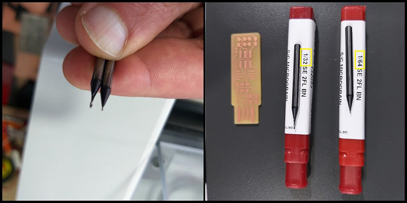
- Milling Bits:
We used two milling bits; for traces 1/64” (0.4 mm), and for interiors 1/32” bit (0.8 mm).
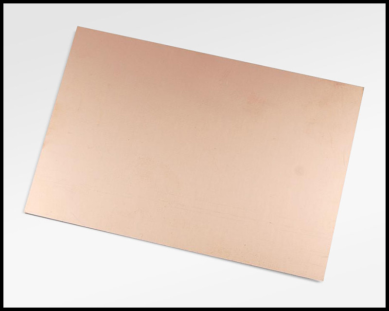
- FR4 PCB:
FR4 is code name for glass-reinforced epoxy laminated sheets. Due to its strength, as well as its ability to withstand moisture and fire, FR4 is one of the most popular PCB materials.
- Double sided tape:
To fixate the PCB on the bed of the milling machine.
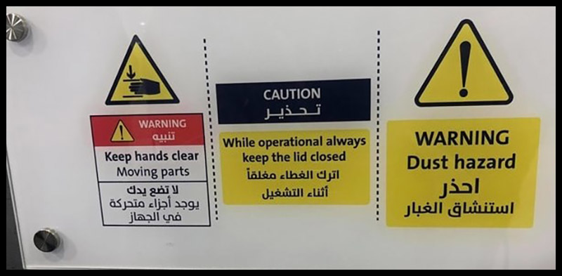
Before operation:
Always read the warnings:
- Dust hazard.
- Keep hands clear from moving parts.
- While operation always keep the led closed.
Assignment steps:
Step one: Getting the files.
From the Fab Academy 2020 Schedule we go to Electronics Production and download two PNG files; under CAM, traces and interior to get familiar to the design rules for your PCB production process.
Step two: Convert PNG files to code that the machine can read.
Preparing Mods:
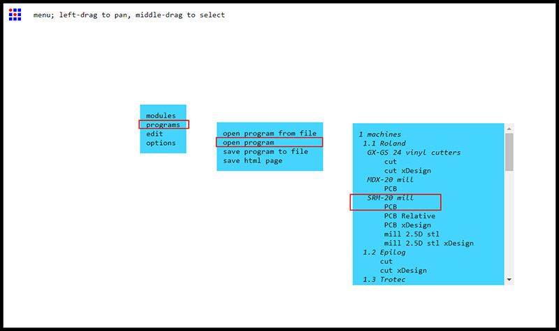
We go to Mods, then choose the next commands:
Programs
Open program
Then choose the machine that we worked on
1.1 Roland
SRM-20 mill
PCB
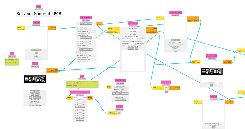
And we will get new windows Roland monoFab PCB, we can put one PNG file next the red arrow.
Also we need to change the Origin Values of X, Y and Z to zeroes; pointed by a blue arrow.
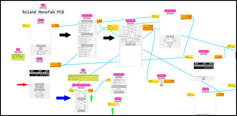
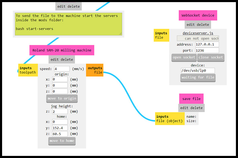
As well as, change the output from Roland SRM-20 milling machine to WobSocket device into Save file.
line test traces program:
- We load traces into the read PNG.
- We select mill traces 1/64” from PCB defaults.
- From mill raster 2D we put 0 to the offset number to get a clean result PCB.
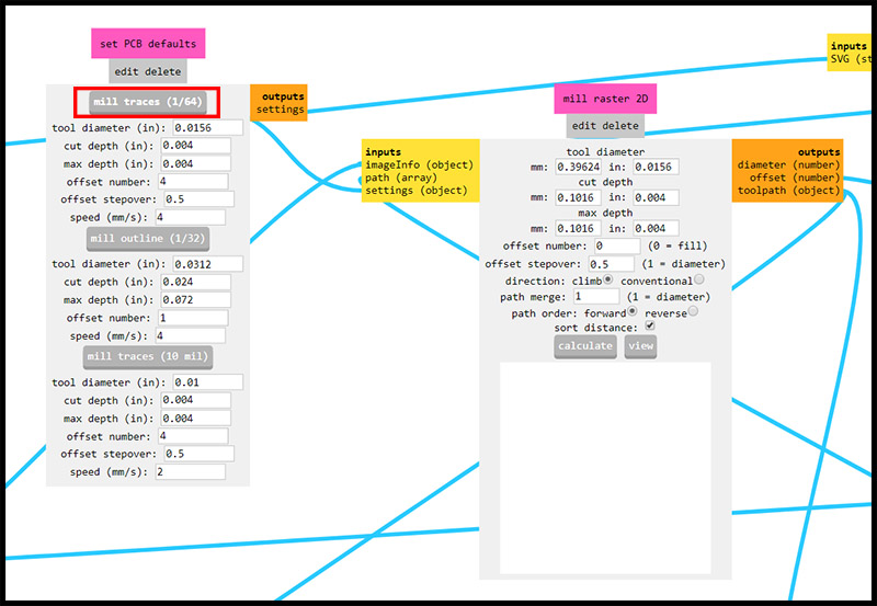
- Then Click calculate, and the file will be save automatically, as a rml file extension.
line test interior program:
- We load interior into the read PNG.
- We select mill traces 1/32” from PCB defaults.
- From mill raster 2D we chose the defaults.
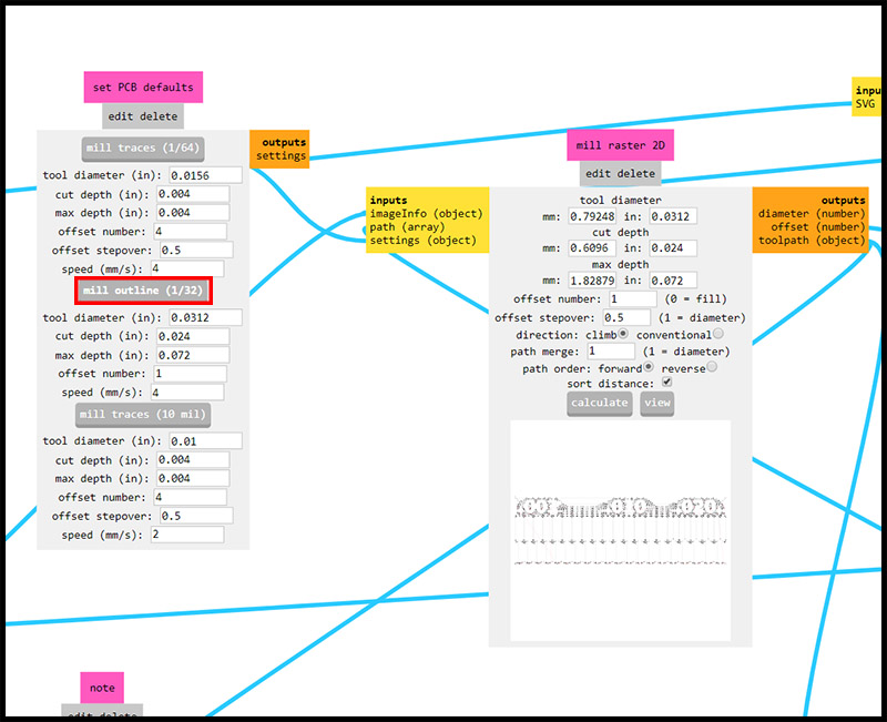
- Then Click calculate, and the file will be save automatically, as a rml file extension.
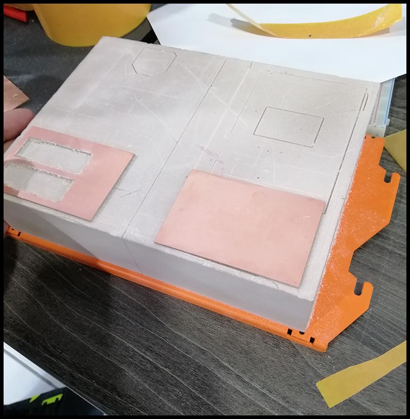
Step three: Milling.
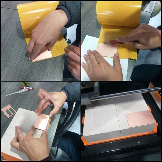
At start, we put a double sided tape on the back of the FR4 PCB, then mounted on the surface of the bed of the milling machine.
Then we load the 1/64 inch mill bit into the spindle of the machine, then zero the X axis and Y axis, and after that we zero out the Z axis by loosen carefully the bit on the surface of the board.
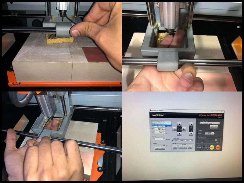
Then choose the User Coordinate System, to get the real zeroes of the axis.
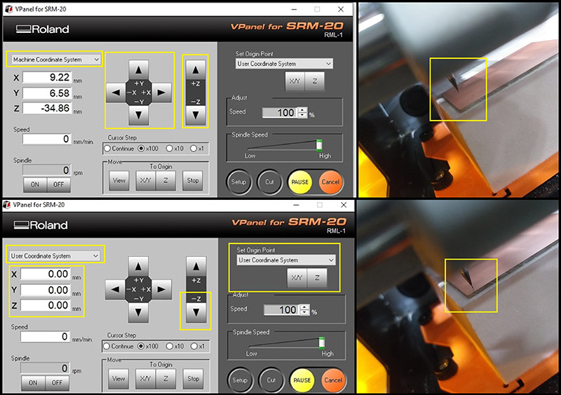
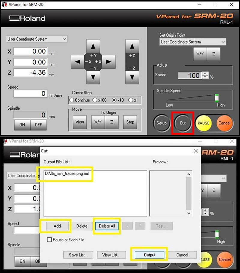
From the cut, we delete aby previous rml programs, then we choose the first file line test traces, and loaded only into the machine by pressing output ,then the machine start.
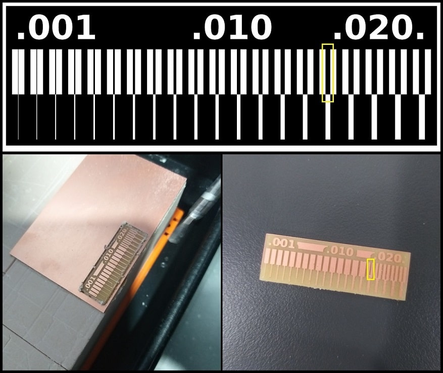
Hero shoot:
We see that code did not produce a toolpath under 0.015 inch because the tip of the mill is 1/64” = 0.015625 inch.
Files used:
individual assignment:
Objective:
Make an in-circuit programmer by milling and stuffing the PCB, test it, then optionally try other PCB processes
Assignment requirements:
Same as the group assignment, but with more parts.
Machine:
Programs:
Tools used:
-
Milling Bits:
We used two milling bits; for traces 1/64” (0.4 mm), and for interiors 1/32” bit (0.8 mm). -
FR4 PCB:
FR4 is code name for glass-reinforced epoxy laminated sheets. Due to its strength, as well as its ability to withstand moisture and fire, FR4 is one of the most popular PCB materials. -
Double sided tape:
To fixate the PCB on the bed of the milling machine. -
Soldering station: To solder the electronics on the PCB.
-
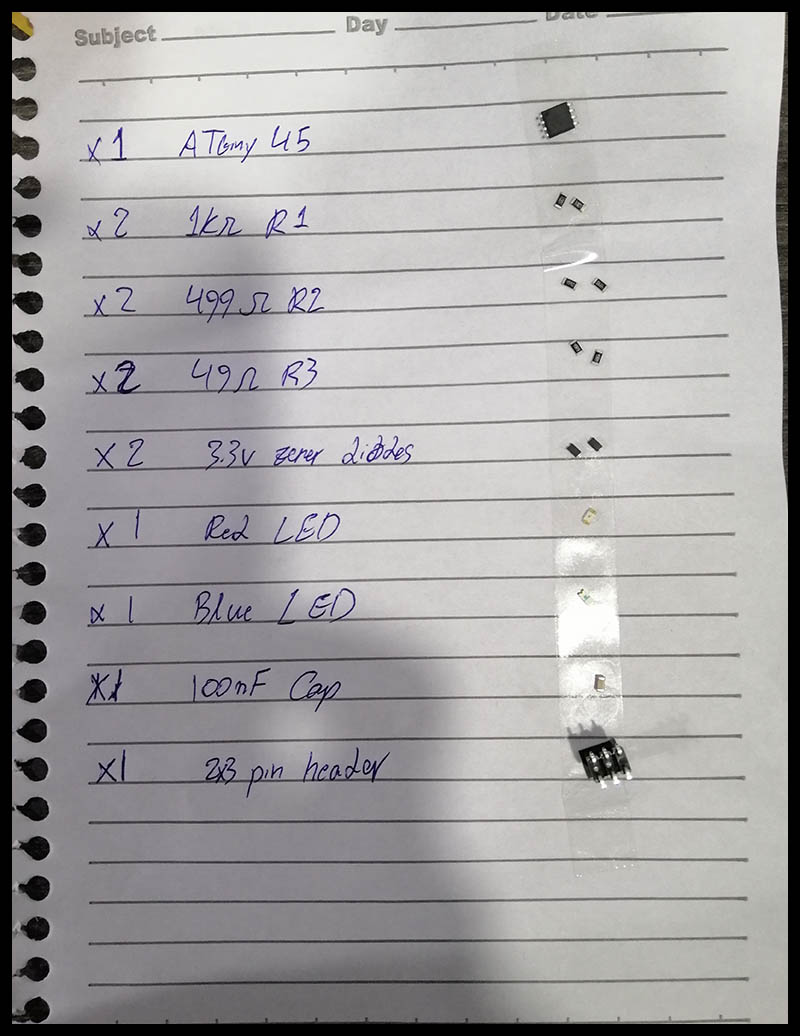
Electronics parts:
1x ATtiny45
2x 1kΩ resistors
2x 499Ω resistors
2x 49Ω resistors
2x 3.3v Zener diodes
1x red LED
1x blue LED, green LED has weak light
1x 100nF capacitor
1x 2x3 pin header
Assignment steps:
Step one: Preparing the RML files
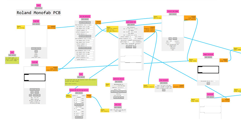
From the fabacademy tutorials, we select FabTinyISP_english under week 4: Electronics production, and then download the next png files:
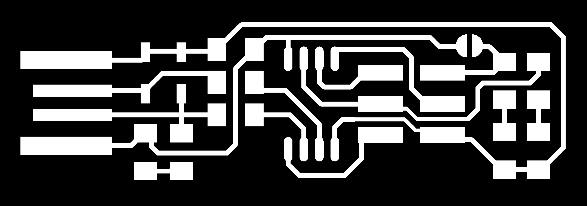
With the same steps in group assignment from modes, we select 1/64 inch bit for Traces and 1/32 inch for Outline cutout.
But I selected for the traces number offset 4 instead of 0 which is fill.
Step two: Milling
At start, I put a double sided tape on the back of the PCB, mounted on the surface of the bed of the milling machine.
With the similar steps of the group assignment, I zero the axis X and Y on the corner, and Z on the surface.
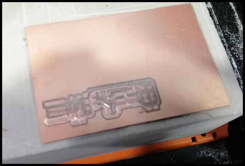
The first mill did work
It did not cut the surface properly I had to redo it one more, and I think the reason that it did not because of the surface was not even; there was a wrap on the edge because bad mounting or the board itself.
Redo the milling.
Second time’s the charm, the traces milling is better than the first one.
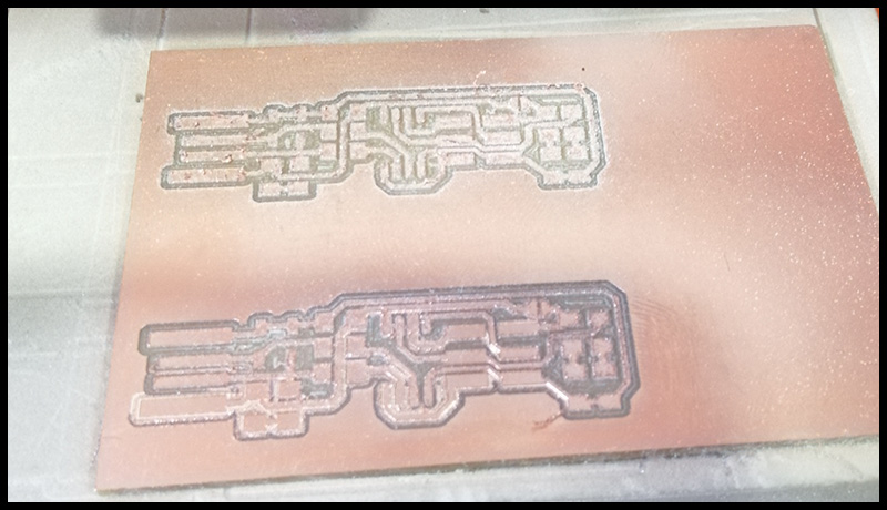
Then cut it out.

And of course I clean it.
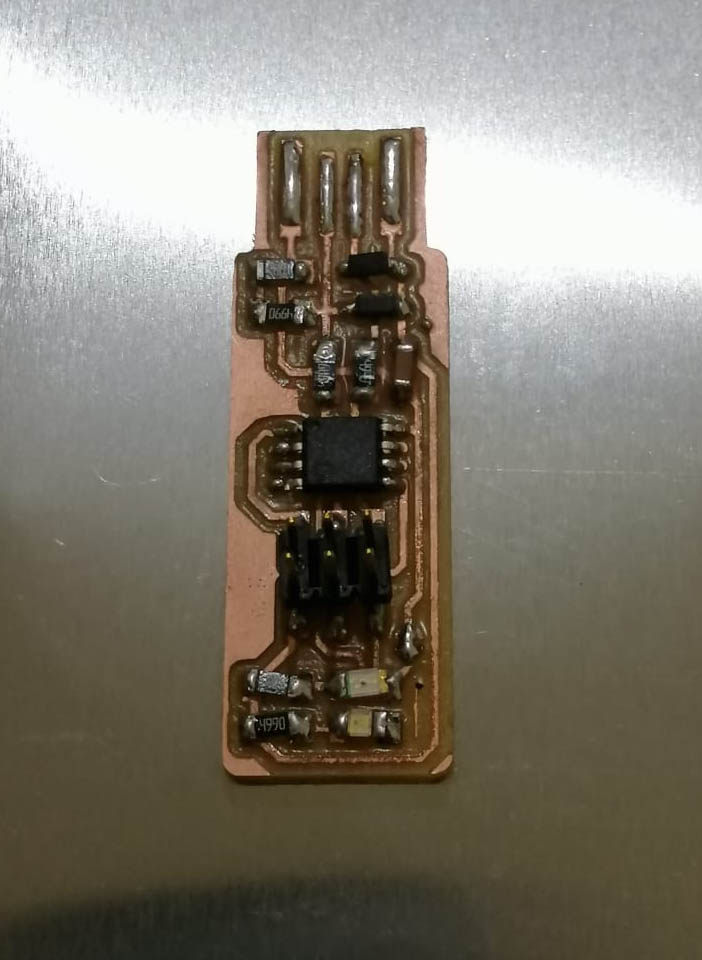
Step three: Preparing the electronics and solder them.
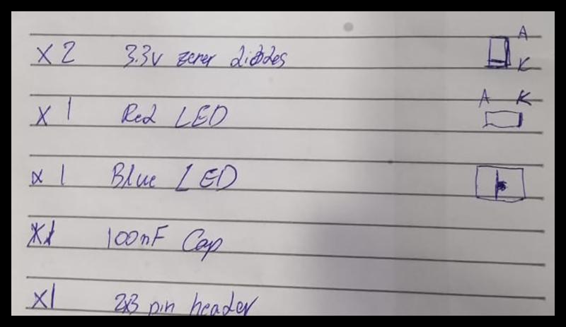
I collected the electronic components and put them on a piece of paper next to their names.
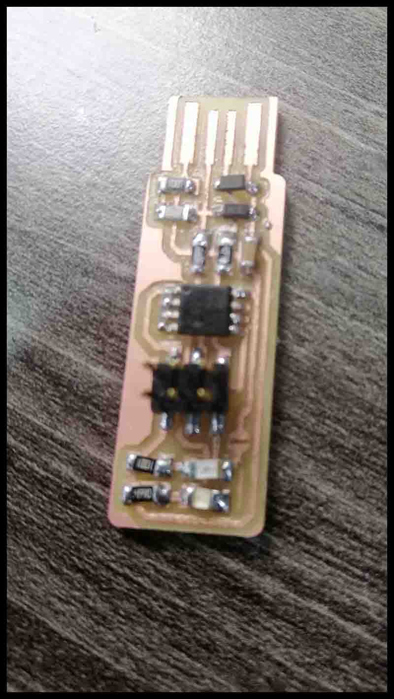
Then solder them, by following the next pictures.
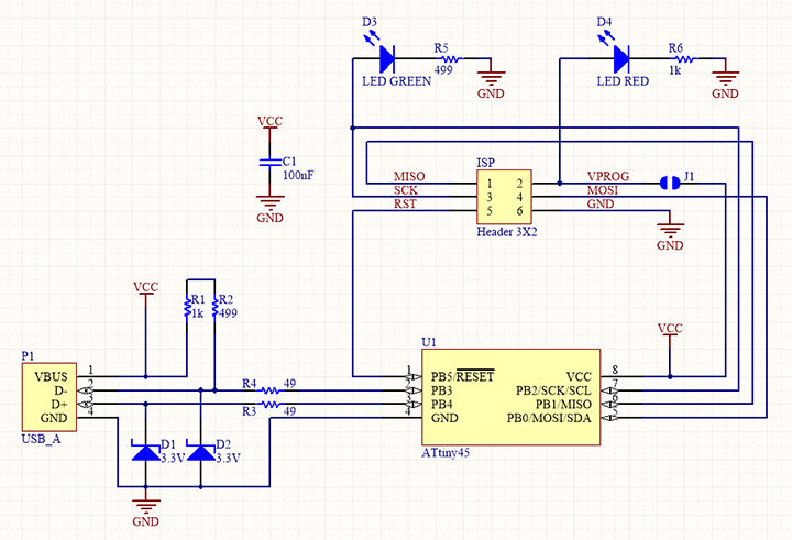
For reference, I drew the indication of the diodes, anode and cathode.
Mistake that I have made:
The order of soldering was wrong, I should have started with the ATtiny (Microcontroller), then other components, and at last the pin header.
Step four: Program the ISP using Linux.
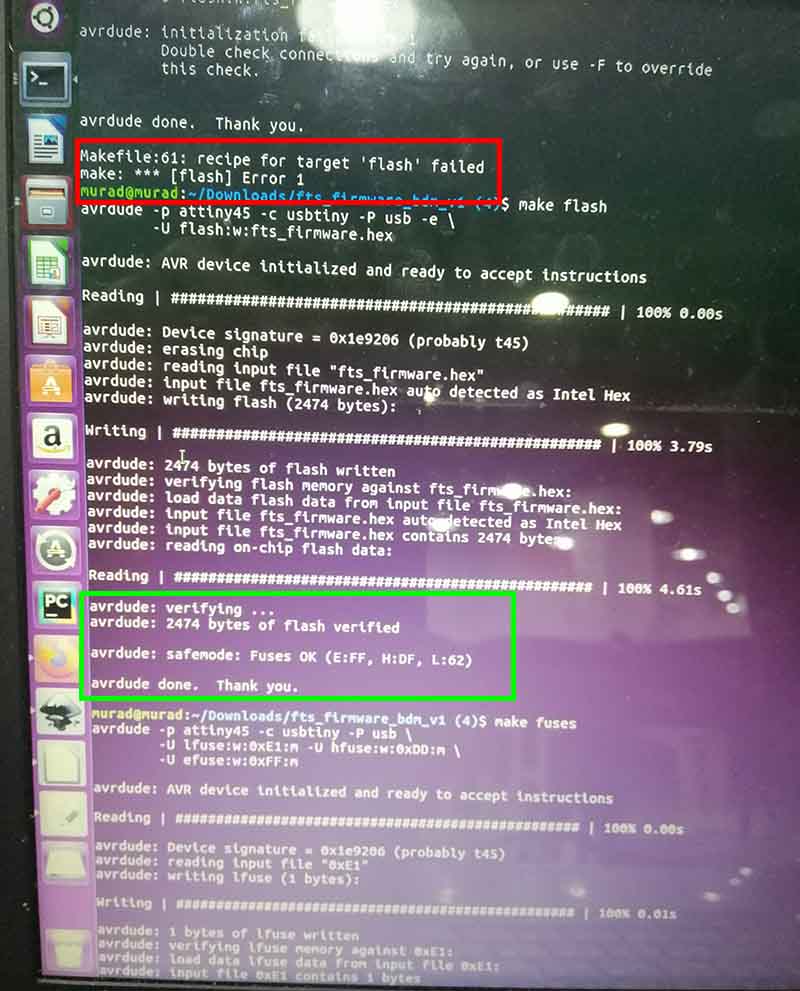
By following this tutorial, when I tried to program the ATtiny45, I’ve got an error:
Makefile:61: recipe for traget 'flash' failed
make: *** [flash] Error 1
I tested the ISP for not connected, wires but the problem was I have forgotten to connect the Jumper J1, I solder it.
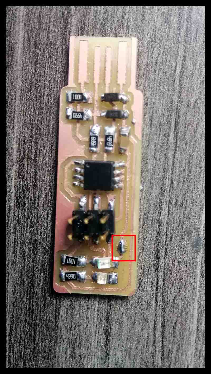
Then program it again and it was verified.
After succeeding programing the ATtiny45, we type
lsusb ///The lsusb command in Linux is used to display the information about USB buses and the devices connected to them
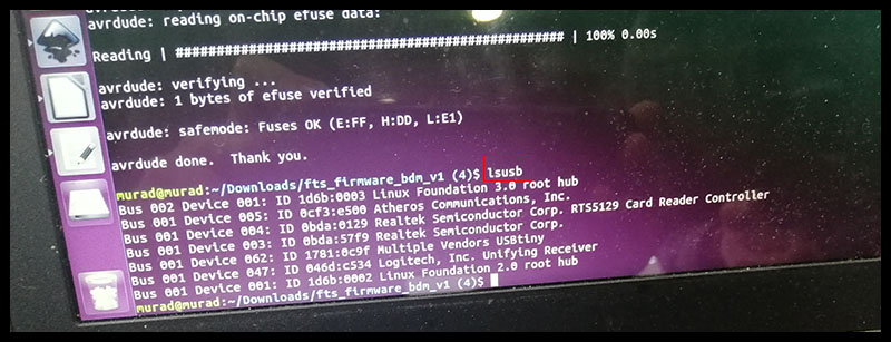
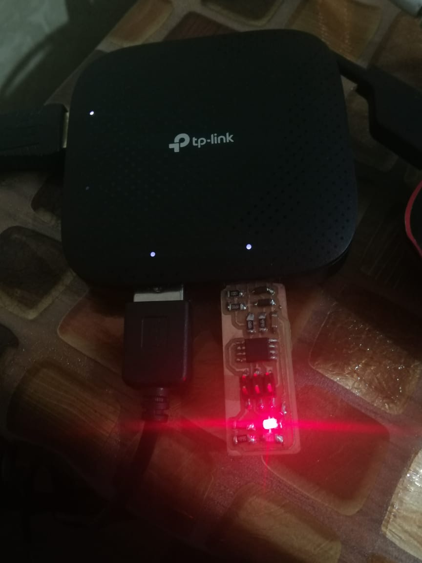
Step five: Check if the ISP works:
By connecting it to a usb hub, and the red LED light up.
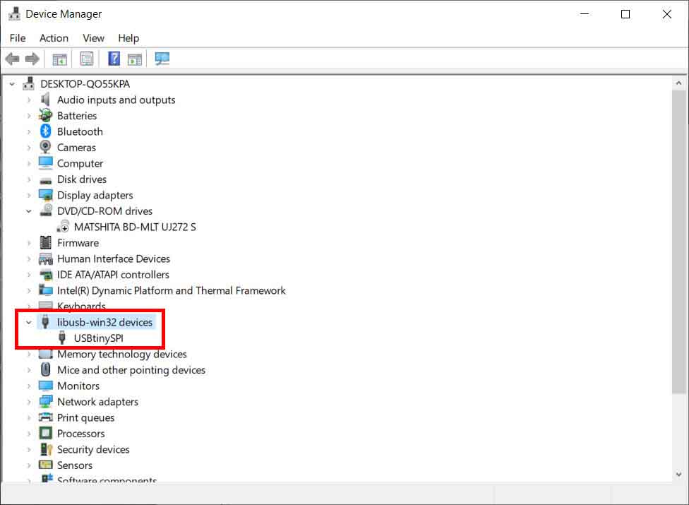
And from the Device Manager, we can see the name of the
And test it to program another controller:
Hero shoot: