12. Output devices
This week we did not have access the lab, so I will update it later when it is done.
Download files:
RML files and PNG files:
Output board Traces and Outline
Eagle Files:
Click to download
Arduino File:
Assignment Objectives:
Individual assignment:
Add an output device to a microcontroller board you’ve designed, and program it to do something.
Group assignment:
Measure the power consumption of an output device.
Group assignment:
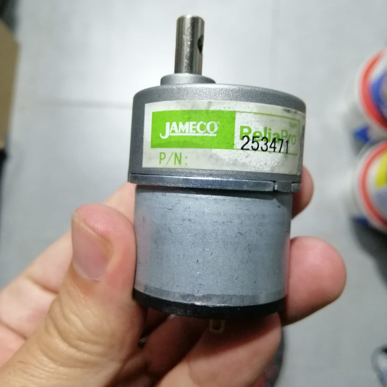
In this part we measured the power consumption of a DC motor using a DC motor output board.
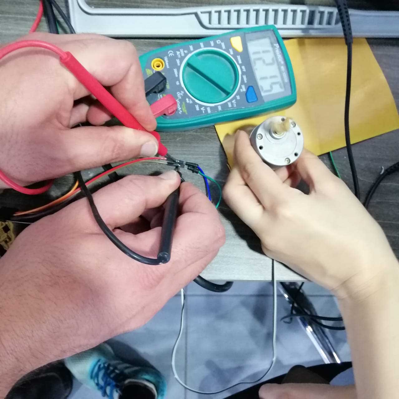
The Power P (in Watt) is calculated by:
P (watts) = V (volts) x I (amps)
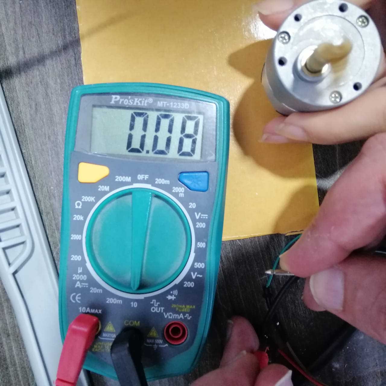
Where V is the voltage across the load and I is the current passing through the load. To measure voltage, the digital multimeter is connected in parallel with the load, and to measure the current passing through, the digital multimeter is connected in series with the load. Remember to move digital multimeter positive test lead to current measuring position before connecting in series with the load.
Measuring the voltage.
Measuring the current.
Individual assignment:
I continued the theme from input week, to design a puzzle shaped PCB, that can be connected to my Hello.World PCB.
In this week, I will design a board to control a DC motor using H-bridge.
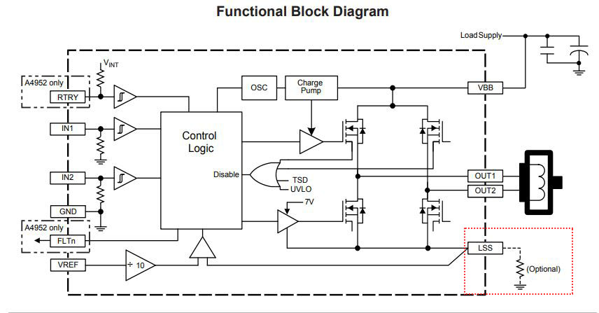
Data sheet of H-BRIDGE A4953:
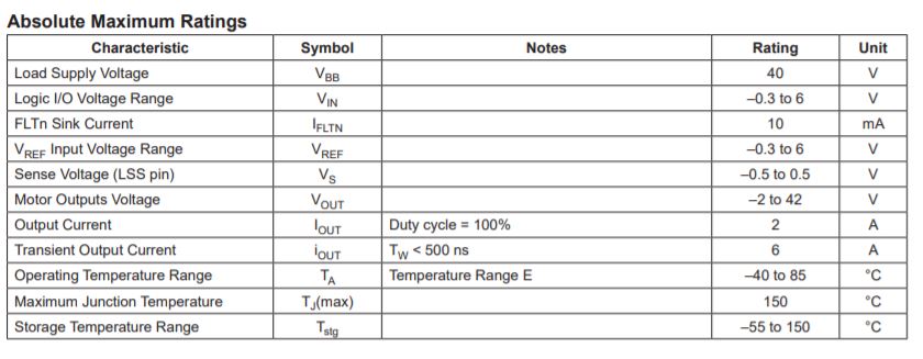
From the data sheet:
-
The H-bridge is designed for pulse width modulated (PWM) control of DC motors, the A4952 and A4953 are capable of peak output currents to ±2 A and operating voltages to 40 V.
-
The maximum values of the inputs and the outputs.
-
The pin layout of the IC.
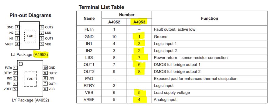
-
The PWM to control the motor, changing the direction, and brake the motor, to help us program the microcontroller.
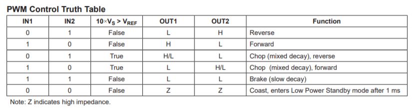
-
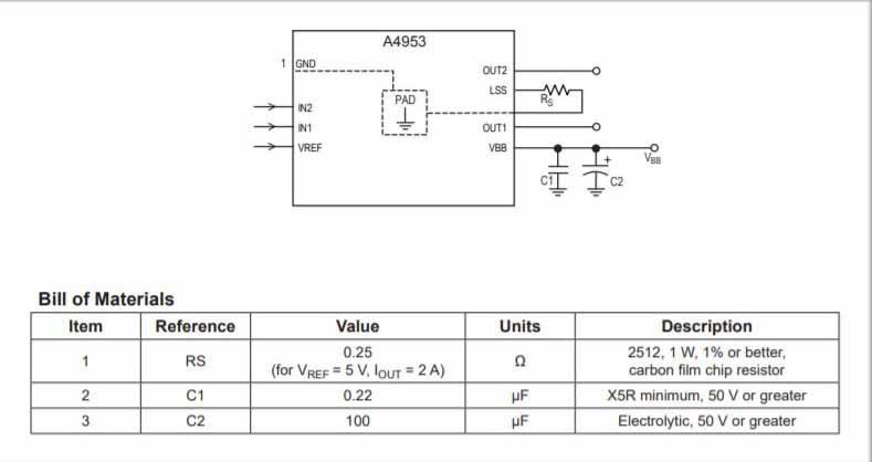
Layout:
The PCB should have a thick ground plane. For optimum electrical and thermal performance, the A4952/A4953 must be soldered directly onto the board. On the underside of the A4952/A4953 package is an exposed pad, which provides a path for enhanced thermal dissipation. The thermal pad must be soldered directly to an exposed surface on the PCB in order to achieve optimal thermal conduction. Thermal vias are used to transfer heat to other layers of the PCB.
The load supply pin, VBB, should be decoupled with an electrolytic capacitor (typically 100 μF) in parallel with a lower valued ceramic capacitor placed as close as practicable to the device.
Design the PCB in eagle:
Determine the parts that we need:
I added a voltage regulator to power the device with no need to connect and 5V source.
| Part name | Footprint | Quantity |
|---|---|---|
| PMIC_H-BRIDGE_A4953_PAD | SOIC8 | 1 |
| VR_REGULATOR-SOT23 | SOT23 | 1 |
| CONN_02X2-PINHEAD-SMD | 2X02SMD | 3 |
| CAP_UNPOLARIZED 1μF | C1206FAB | 1 |
| CAP_UNPOLARIZED 10μF | C1206FAB | 1 |
| Resistor 1k | R1206FAB | 1 |
| LED | LED1206FAB | 1 |
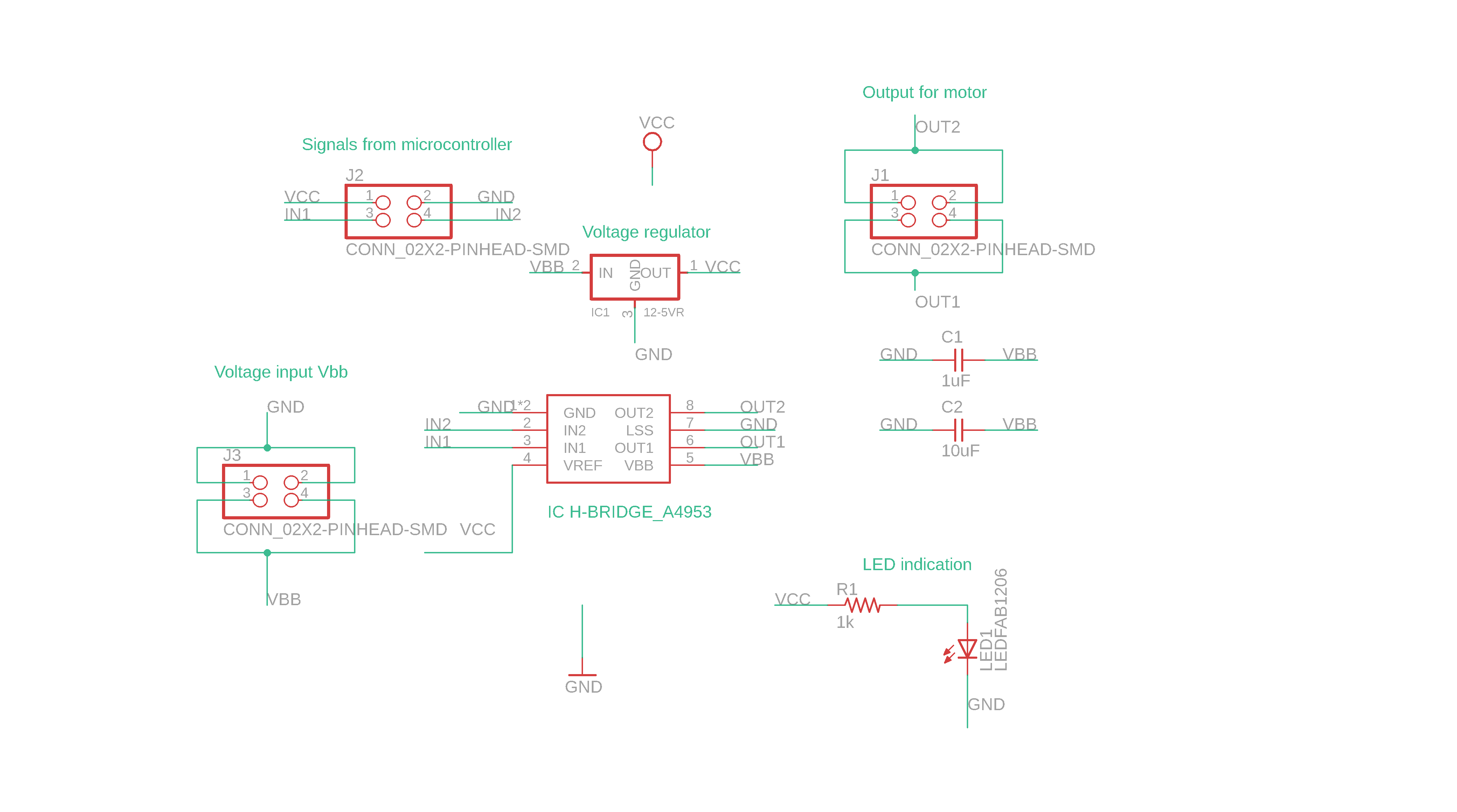
Prepare the Schematic:
I have added the parts from the table, where I have three jumpers, one to input voltage source Vbb, one to give the output to the motor, and the last one to get the signals from the microcontroller, as well as, power it with +5V and ground.
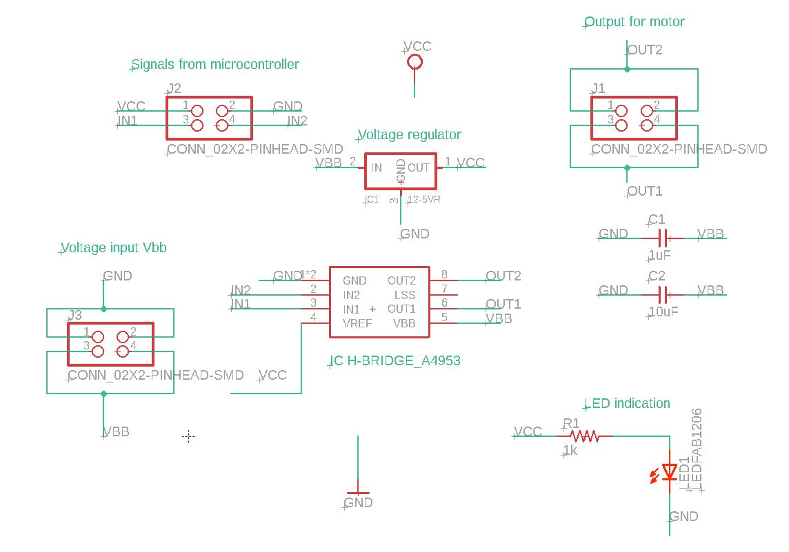
Also, I have added a LED to indicate that the board is working when it is connected to a power source.
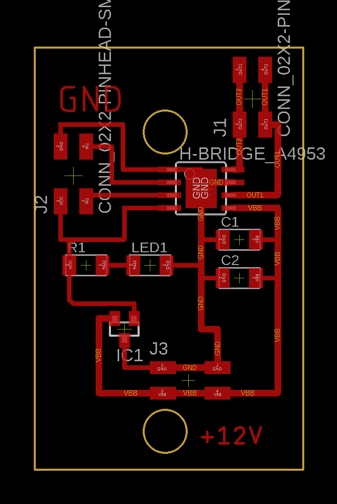
Board:
I have loaded the fab DRC file, under Sizes tab I changed the *minimum width* value from *10mil* to *16mil*, so when I do the *Autorouter* I get the right value.
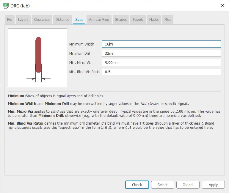
Also that I have keep in mind that the lines from *Vbb* and its *ground* need to be **24mil** width.
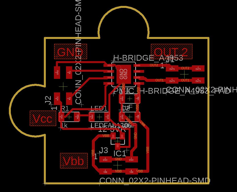
Also I have put indications for *Vbb*, the gournd, the output for the motor, and *Vcc* to not be mixed up with the jumpers, and it is easier to understand.
I have made a profile to prepare the PCB file to be exported, just showing the pads, wire lines, and the dimension of the PCB, you can edit it in the yellow highlighted button.
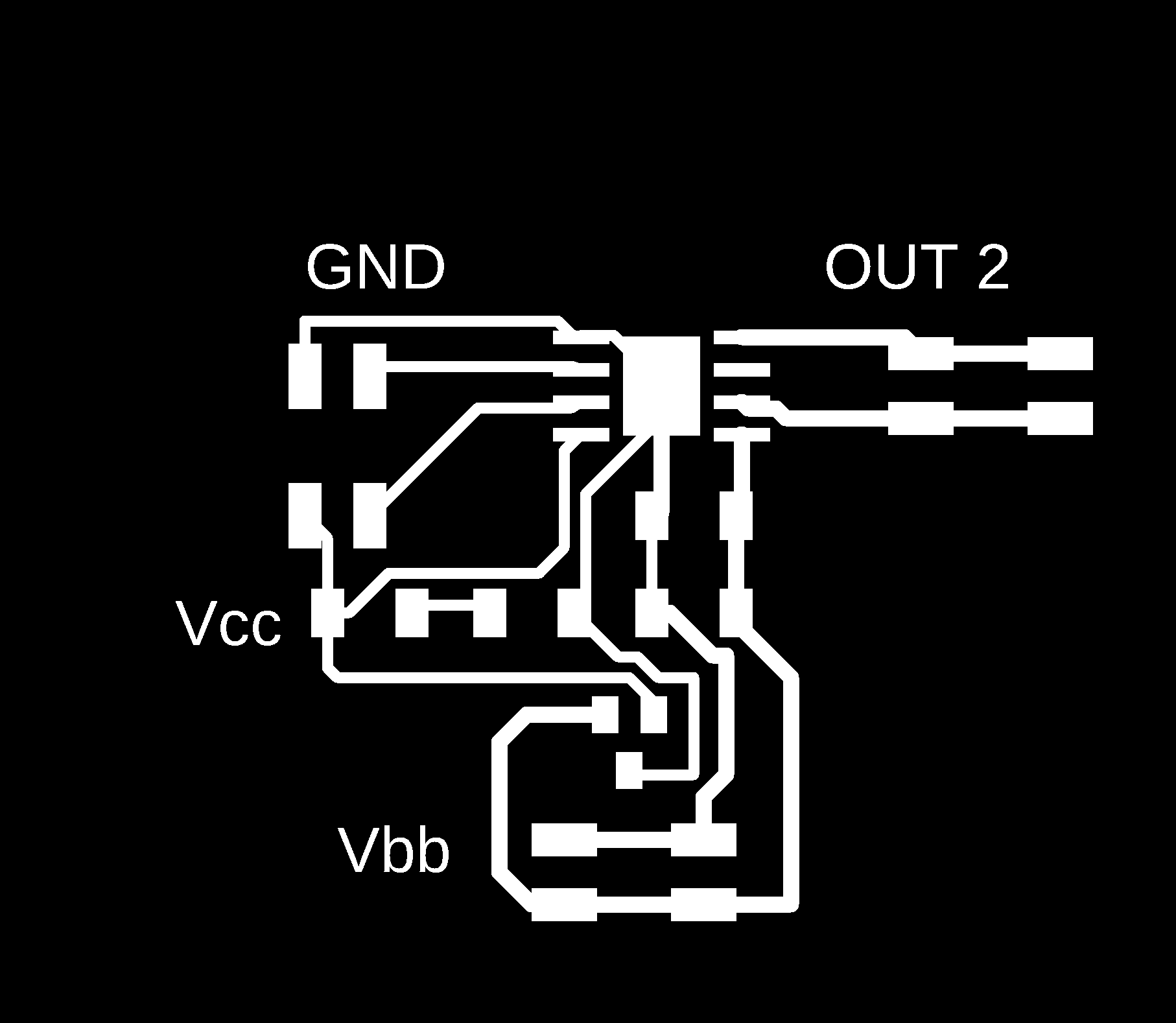
I exported it as monochrome, with 1000 DPI.

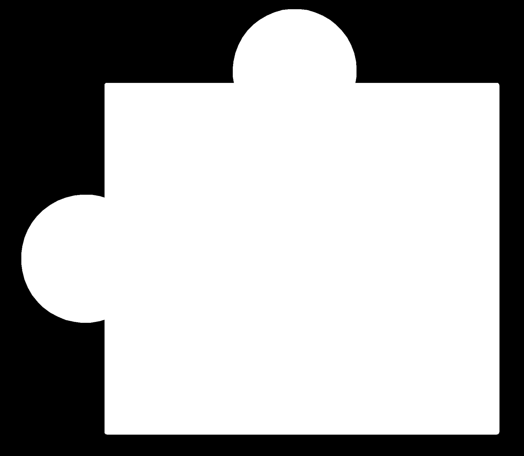
Using photoshop, I have made the traces and cut images:
Traces:
Outline:
Generate RML files from mods:
Like the process of the input week, we make sure that the resolution is 1000 DPI for both files, and the origin is changed x, y, z to zero
For traces, the bit selected is *1/64"*, and the offset number is *4*.
From mods page we open program Ronald SRM-20mill.
Machines --> Ronald --> SRM-20 mill--> PCB
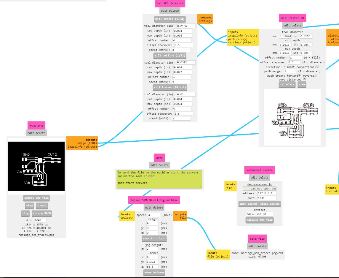
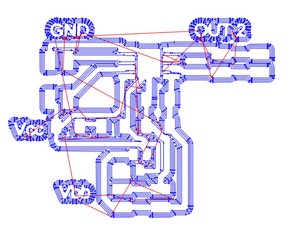
Then I checked the path file to make sure there are no connected wires and/or pads, it should be at least on line between the wire and/or pads.
For the outline, the bit selected is *1/32"*, and the offset number is the default *1*.
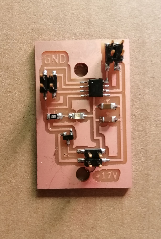
Problem that I have:
After getting back to the lab, I have milled and soldered the output board and try to started it but I did not work, the same problem happened with my colleague Hani with his board, after a week, he figured it out the problem was we both did not connected the LSS to the ground, while it is mentioned in the data sheet it was optional!!!
Redo the board:
I have just connected the LSS to the ground, and resize the board to be used on my final project.
Updated schematics:
Updated board design:
Code:
It is a simple on/off with timer, controlled by the ATtiny44
const int motorPin1 = 0;
const int motorPin2 = 1;

const int LEDred = 3;

void setup() {
  // put your setup code here, to run once:
  pinMode(motorPin1, OUTPUT);
  pinMode(motorPin2, OUTPUT);
  pinMode(LEDred, OUTPUT);
}

void loop() {
  digitalWrite(motorPin1, HIGH);
  digitalWrite(motorPin2, LOW);
  digitalWrite(LEDred, HIGH);
  delay(5000);

  digitalWrite(motorPin1, LOW);
  digitalWrite(motorPin2, LOW);
  digitalWrite(LEDred, LOW);
  delay(3000);

  digitalWrite(motorPin1, LOW);
  digitalWrite(motorPin2, HIGH);
  digitalWrite(LEDred, HIGH);
  delay(5000);

  digitalWrite(motorPin1, LOW);
  digitalWrite(motorPin2, LOW);
  digitalWrite(LEDred, LOW);
  delay(3000);
}
Fabricate the board:
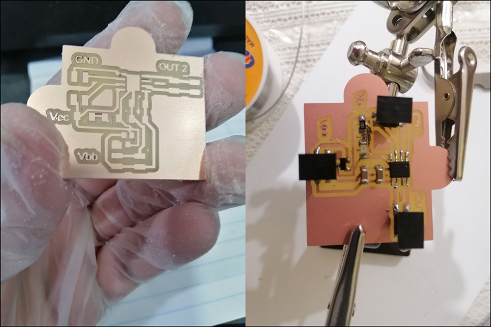
Milling the board:
Videos of milling the old board:
Old board before and after soldering, notice the LSS pin is not connected to the ground.
Hero shoot!!!
New board H-bridge:
Video of the board and the code working:
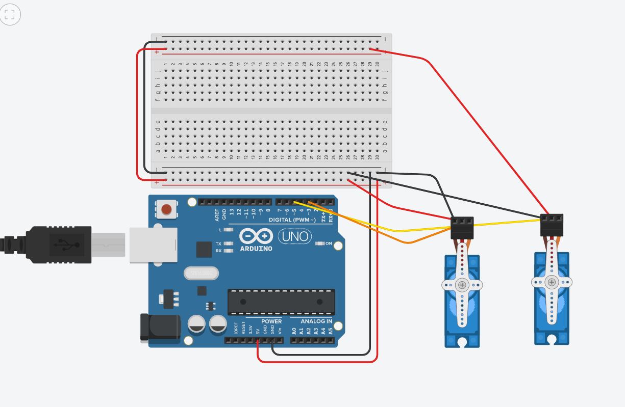
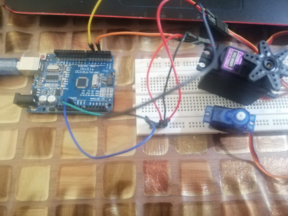
Working with Arduino kit:
I did a small project, where I connected two servo motors to an Arduino, where the output signal to servo one is not the same of the servo 2.
And I program is to move to three locations 0°, 90° , and 180°.
| Servo 1 | Servo 2 |
|---|---|
| 0° | 90° |
| 90° | 180° |
| 180° | 0° |
Connection:
The servo has three pins; Voltage in, ground, and signal, where the voltage is connected to 5V+ from the Arduino, ground to ground, and signal to pin 3 and pin 5 for each servo.
Code:
// Including the Servo library
#include <Servo.h>
// Declare the Servo pins
int servoPin1 = 3;
int servoPin2 = 5;
// Create a servo objects
Servo Servo1; Servo Servo2;
void setup() {
   // We need to attach the servo to the used pins number
   Servo1.attach(servoPin1);
   Servo2.attach(servoPin2);
}
void loop(){

   Servo1.write(0);     // Make servo1 go to 0 degrees
   Servo2.write(90);    // Make servo2 go to 90 degrees
   delay(1000);

   Servo1.write(90);    // Make servo1 go to 90 degrees
   Servo2.write(180);   // Make servo2 go to 180 degrees
   delay(1000);

   Servo1.write(180);   // Make servo1 go to 180 degrees
   Servo2.write(0);     // Make servo2 go to 0 degrees
   delay(1000);
}
Parts used:
- Arduino UNO ATMEGA328P.
- Mini servo motor SG90 9G servo.
- Servo motor MG995 metal gear 180 degrees.