13. Interface and application programming
Download files:
Processing and Arduino files for tachometer:
Codes for NTC bridge:
Assignment Objectives:
Individual assignment:
Write an application that interfaces a user with an input &/or output device that you made.
Group assignment:
Compare as many tool options as possible.
Group assignment:
For the group assignment this week we have to compare as many tool options as possible .
-
We started by explaining Processing and interface is similar to Arduino, but it uses Java script, and see the reference page, the examples page, and the tutorials page.
-
Then we discussed how we can use Python and download pyserial so we can communicate from any Python programs like Pycharm, with the tkinter library to make a User Interface UI, as well as, VPython library helps to create navigable 3D displays and animations easily.
-
We discussed Firefly and this a addon for grasshopper in Rhino also explained that we can use it in many different ways such as creating an interface with just the sound of the sea and much more.
-
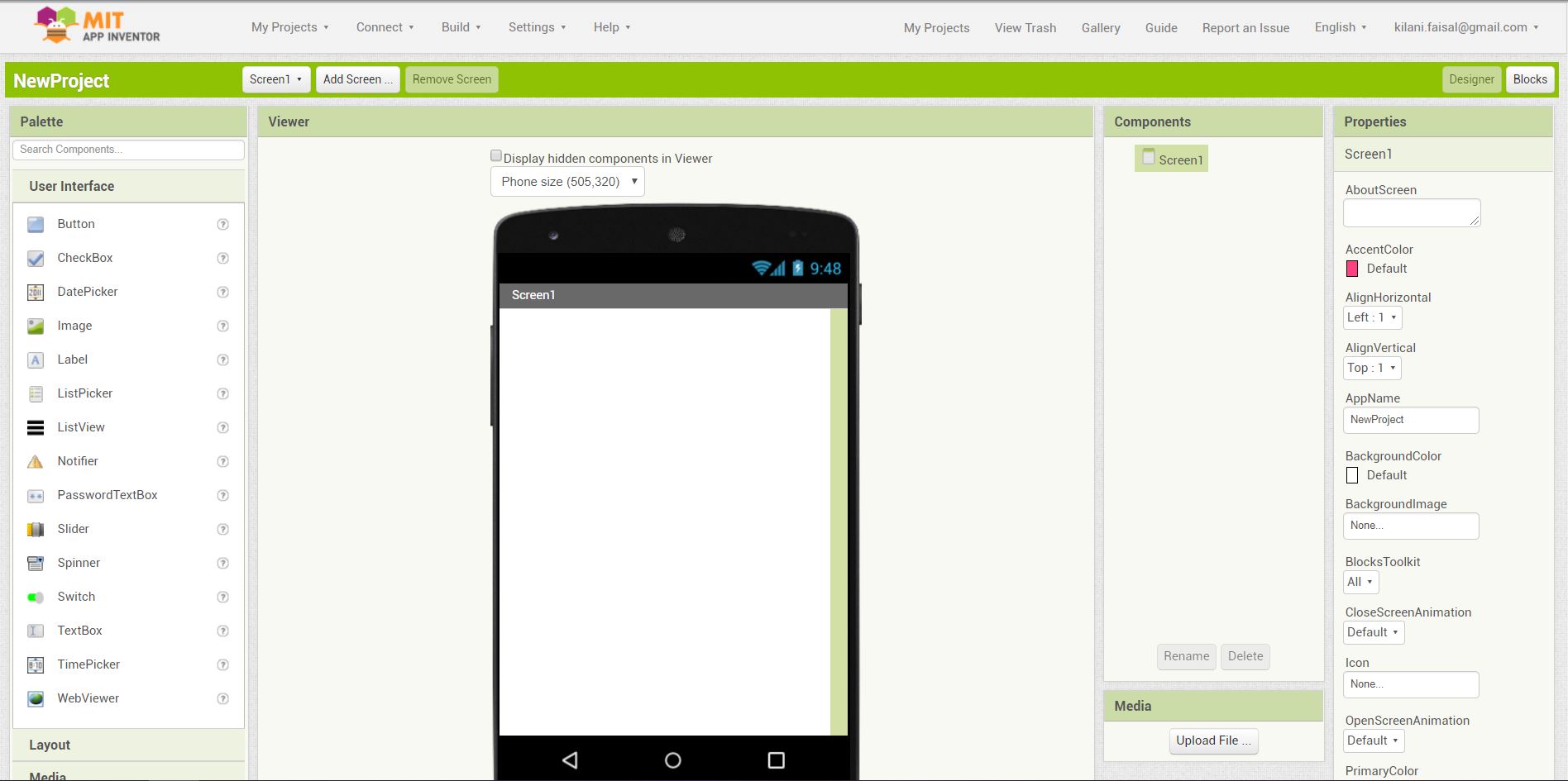
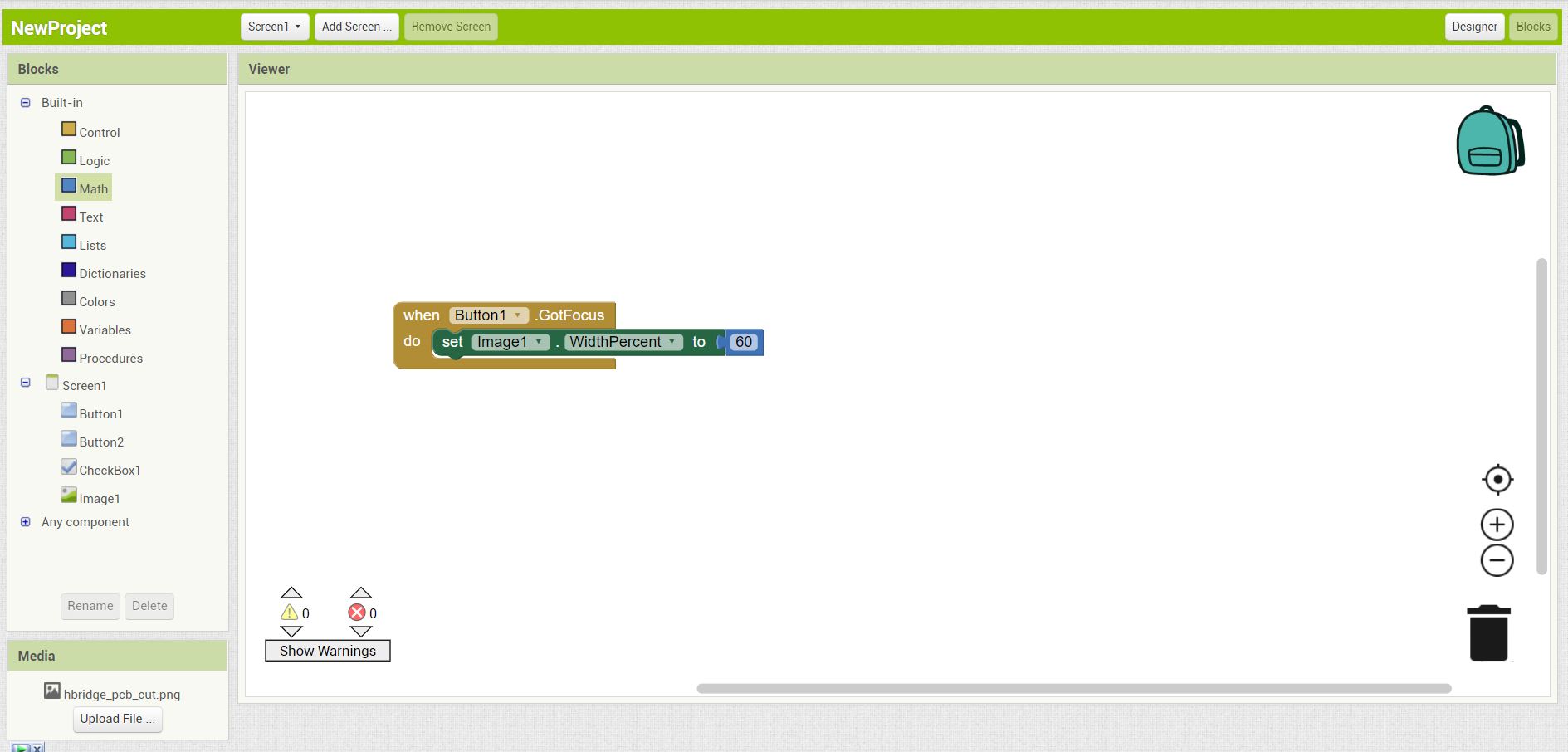
MIT app inventor is a visual programming environment that allows everyone to build fully functional apps for smartphones and tablets. It use blocks-based tool facilitates the creation of complex, high-impact apps in significantly less time than traditional programming environments.
The MIT App Inventor project seeks to democratize software development by empowering all people, especially young people, to move from technology consumption to technology creation.
1- It has an easy interface, where you can add element by dragging them into the phone screen from the left side, first we see the designer UI, when we start the program.
2- There are many tools to add and customize, and we can use the electronics of the phone; like camera, microphone and Bluetooth, and utilize them to certain jobs.
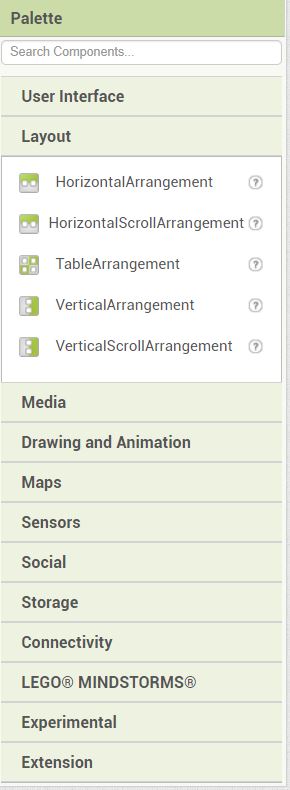
3- When adding elements to the program, we have the option to change the properties like text, scale, font.
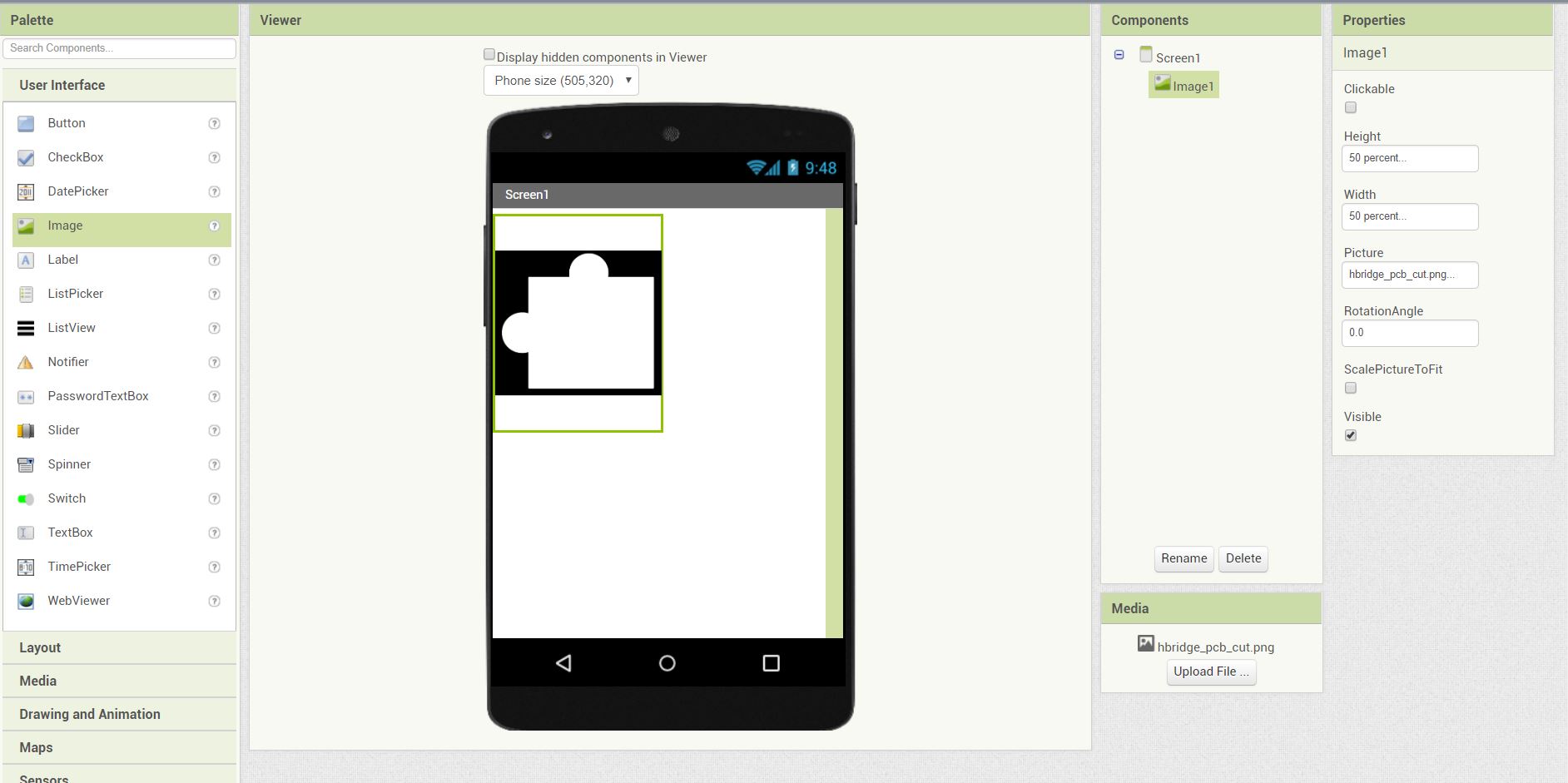
4- Also change the shapes and color of the added elements.
5- In the block UI, we can program the app just by adding blocks to each-other to preform an action.
Individual assignment:
I have worked on a tachometer sensor; measure the speed of a motor in RPM, by sending data from Arduino to Processing using USB Serial communication.
This work is not consider part of the assignment
Because the COVID-19 situation and I did not use an input &/or output device that I have made. Nevertheless, I used a tachometer sensor that I have already own to pass the week until I have access to the lab again.
Processing:
About Processing:
Processing is an open-source graphical library and integrated development environment built for the electronic arts, new media art, and visual design communities with the purpose of teaching non-programmers the fundamentals of computer programming in a visual context.
Prepare the image files:
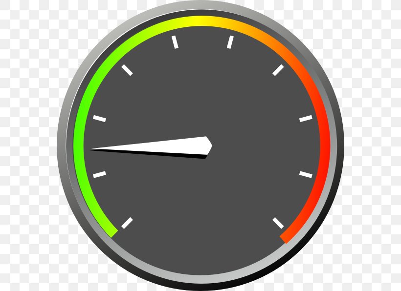
I have downloaded a tachometer gauge picture and sperate it into two files using Photoshop:
- The gauge.
- The indicator.
The tachometer gauge picture.
Then separate it into two images:
Image one:
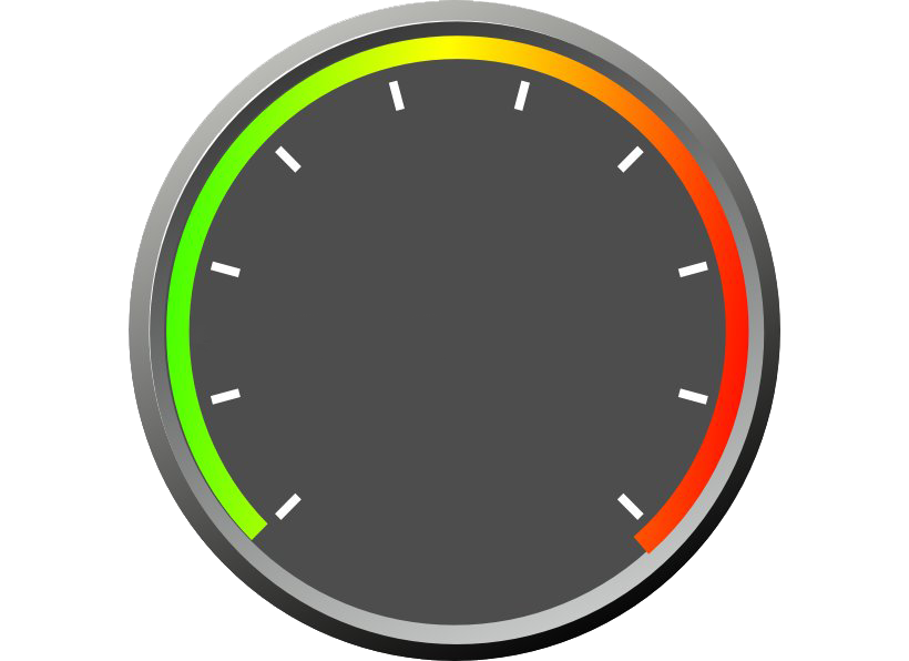
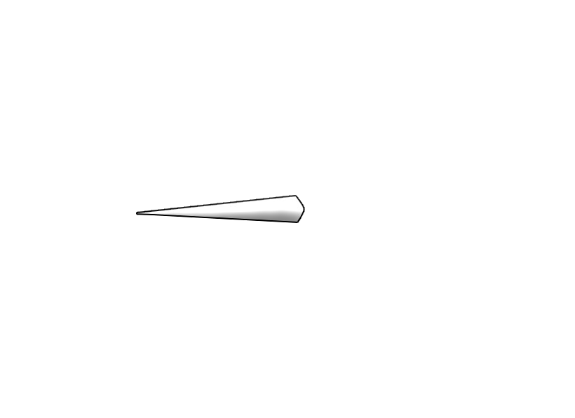
Image two:
Building the code:
I have loaded the images first by dragging the pictures into the file, to load a file directory data within the processing files.
Then put the code to define them into the code:
PImage bg;          // Background; the gauge
PImage indicator;   //
And within the void setup(), the name of the images:
bg = loadImage("tachometer_base.png");
indicator= loadImage("tachometer_indicator.png");
And inside the void draw():
background(bg);   // load the gauge as image background


// Indicator
rotate(radians(int(output)));   //radians to convert it from radians.
image(indicator, 0, 0);
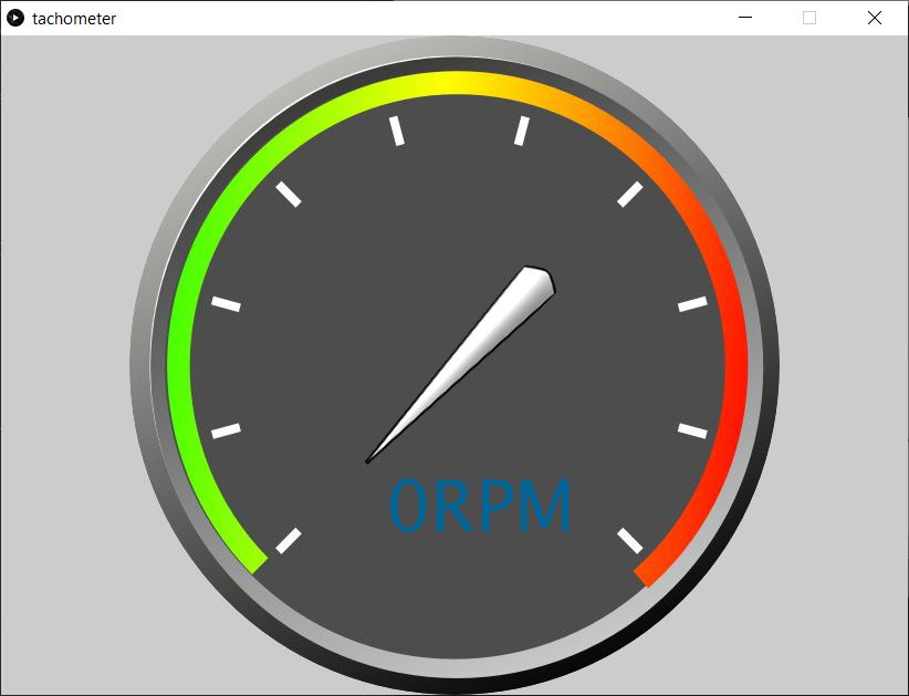
Problem 1:
When I tried to rotate the indicator image, the rotation was not around the center of the window, and the processing origin point is from the top left as we can see from the example.
The second issue that the indicator image, was the same size of the background and needed to be fixed.

Rewrite the code:
I added the first translate, to be centered in the middle of the window, but it was from the top left.
The second translate, was to center the image to the center.
  // Indicator
translate(bg.width/2, bg.height/2);
rotate(radians(int(output)));
translate(-indicator.width/2, -indicator.height/2);
image(indicator, 0, 0);
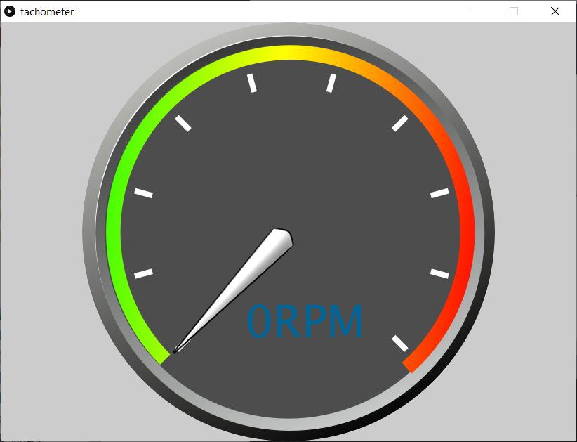
Problem 2:
The indicator was centered wrong, and rotate and translate were in good position.
Fix the image:
I changed the image to double its width to fix the problem.
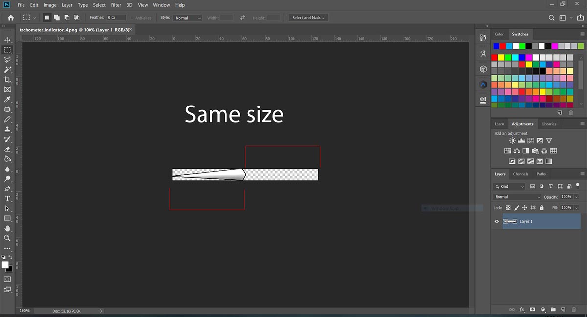
By testing the rotation, I found the minimum and the maximum values of rotation is from -45 to 255 degrees.
Prepare the serial communication between Processing and Arduino:
First we load up the library import processing.serial.*;, then in the void setup() we put the code:
arduino = new Serial(this, Serial.list()[0], 9600);
arduino.bufferUntil('.');
arduino.clear();                   // Throw out the first reading, in case we started reading
delay(1000);
And add a serial event to convert the incoming data from Arduino from string to Integer.
By finding the . (dot), the program know that is the end of each data comes from Arduino.
void serialEvent (Serial arduino) { // starts reading data from the Serial Port
  // reads the data from the Serial Port up to the character '/n' new line and puts it into the String variable "data".
  data = arduino.readStringUntil('.');
  data = data.substring(0, data.length()-1);

  // converts the String variables into Integer
  input= int(data);
  println(data);
  println(input);
}
Map the data:
The next code is to map the data from (0 to 11300) to -45 to 255 degrees, to rotate the indicator.
//Convert data to rotation
output=map(input, 0, 11300, -45, 255);
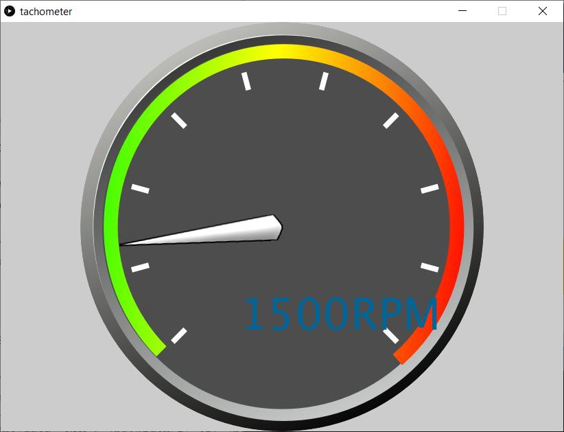
Put the values in text:
This code is to define the text, and put the incoming RPM data in text.
//RPM in text
textSize(64);
fill(0, 102, 153);
text(data+"RPM", (bg.width/2)-62, (bg.height/2)+150);
Prepare Arduino:
I have a good program that use to measure sensor module, by measuring the period between pulses using the micros() function to get the RPM (Revolutions Per Minute) from a sensor on pin 2.
Made by InterlinkKnight.
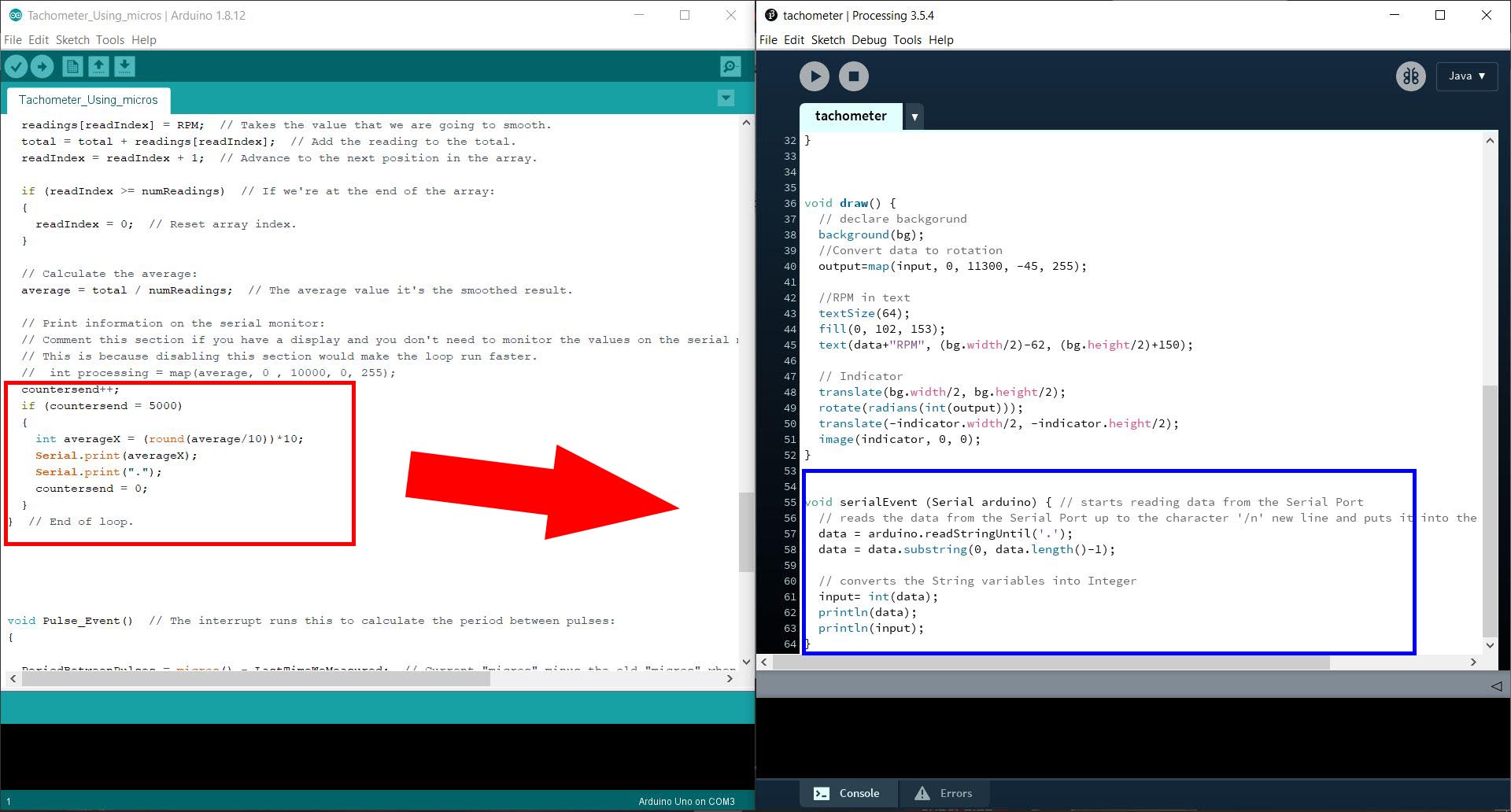
I made some modification to the program to communicate with Processing.
- If statement with a counter countersend to slow down the data sent to the Processing.
- Round to the second digit; int averageX = (round(average/10))*10;.
- Added Serial.print("."), so the Processing knows the end of each data sent.
countersend++;
if (countersend = 5000)
{
  int averageX = (round(average/10))*10;
  Serial.print(averageX);
  Serial.print(".");
  countersend = 0;
}
With this code from Processing, that will read and covert the data (from Arduino) back to Integer.
void serialEvent (Serial arduino) { // starts reading data from the Serial Port
  // reads the data from the Serial Port up to the character '/n' new line and puts it into the String variable "data".
  data = arduino.readStringUntil('.');
  data = data.substring(0, data.length()-1);

  // converts the String variables into Integer
  input= int(data);
  println(data);
  println(input);
}
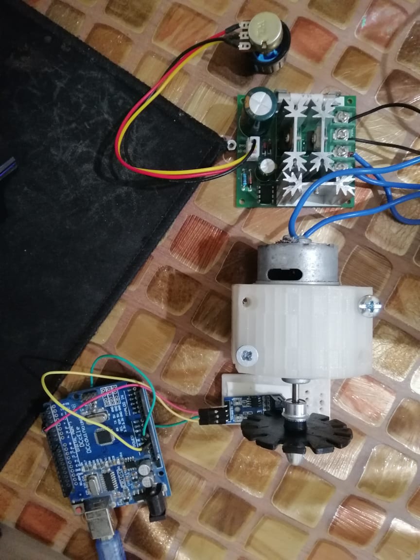
The circuit:
Parts used:
-
Arduino Uno.
-
Speed Encoder Sensor Module for Arduino.
-
DC motor driver.
-
Motor driver circuit, with input of 12 volts.
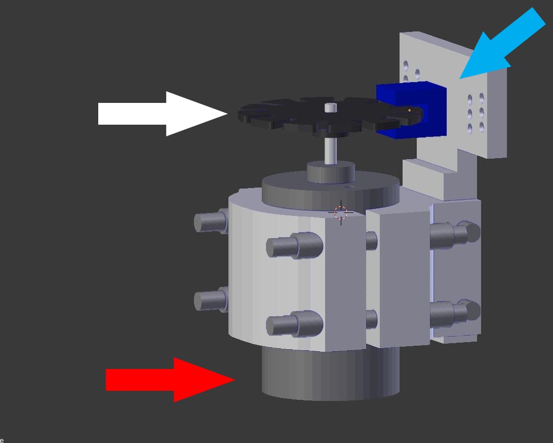
This is a DC motor mount that I had printed two years ago, to measure the RPM, using an encoder and a disk with twelve teeth to give pulses to the microcontroller.
-
Red arrow: DC motor.
-
White arrow: Disk for the encoder, twelve teeth.
-
Cyan arrow: Encoder Sensor.
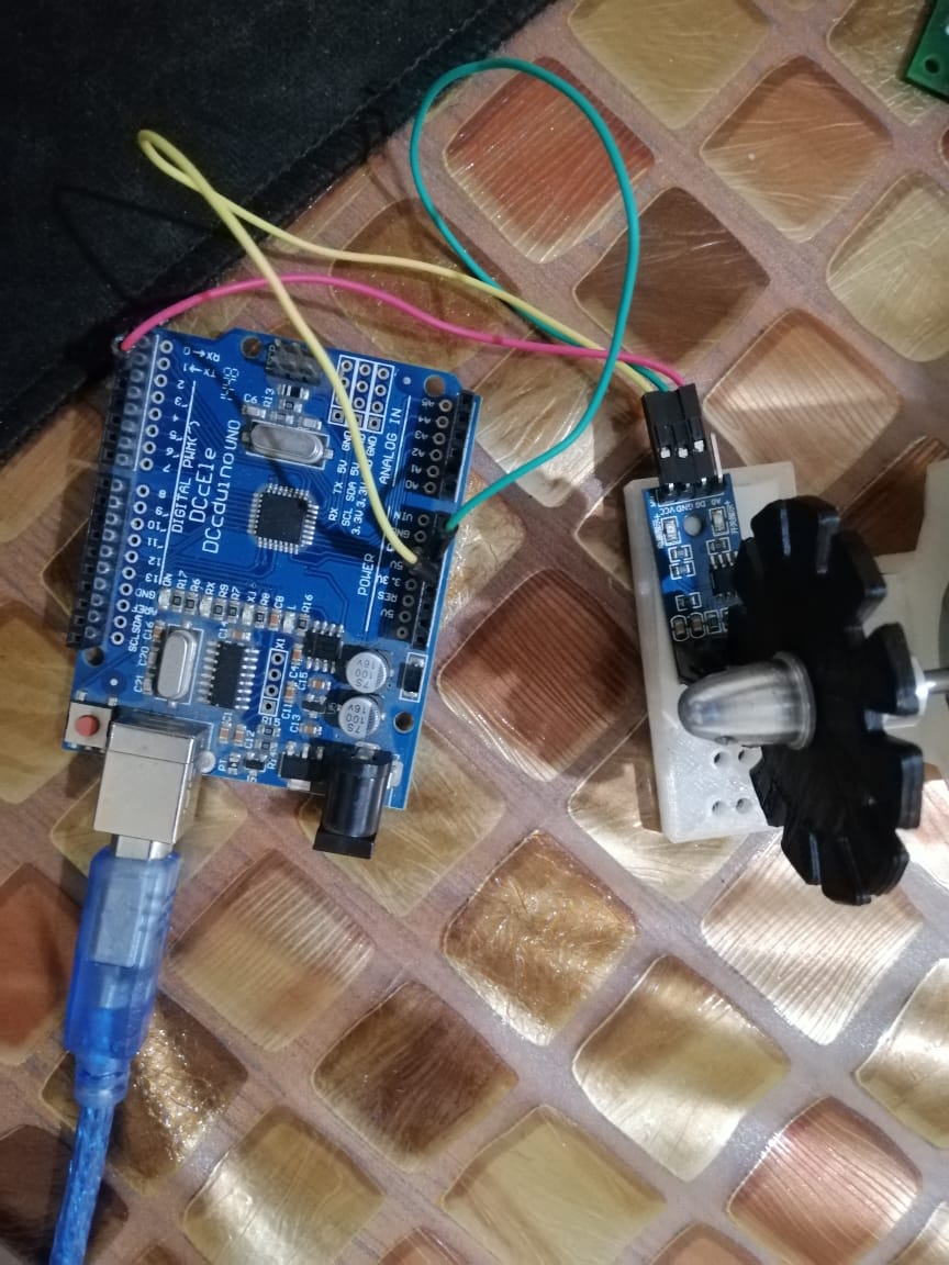
The Encoder is connected to the Arduino; +5V, grounds, and digital pin to Arduino pin 2.
DC motor driver with potentiometer to control the speed [RPM], the income voltage is 12V.
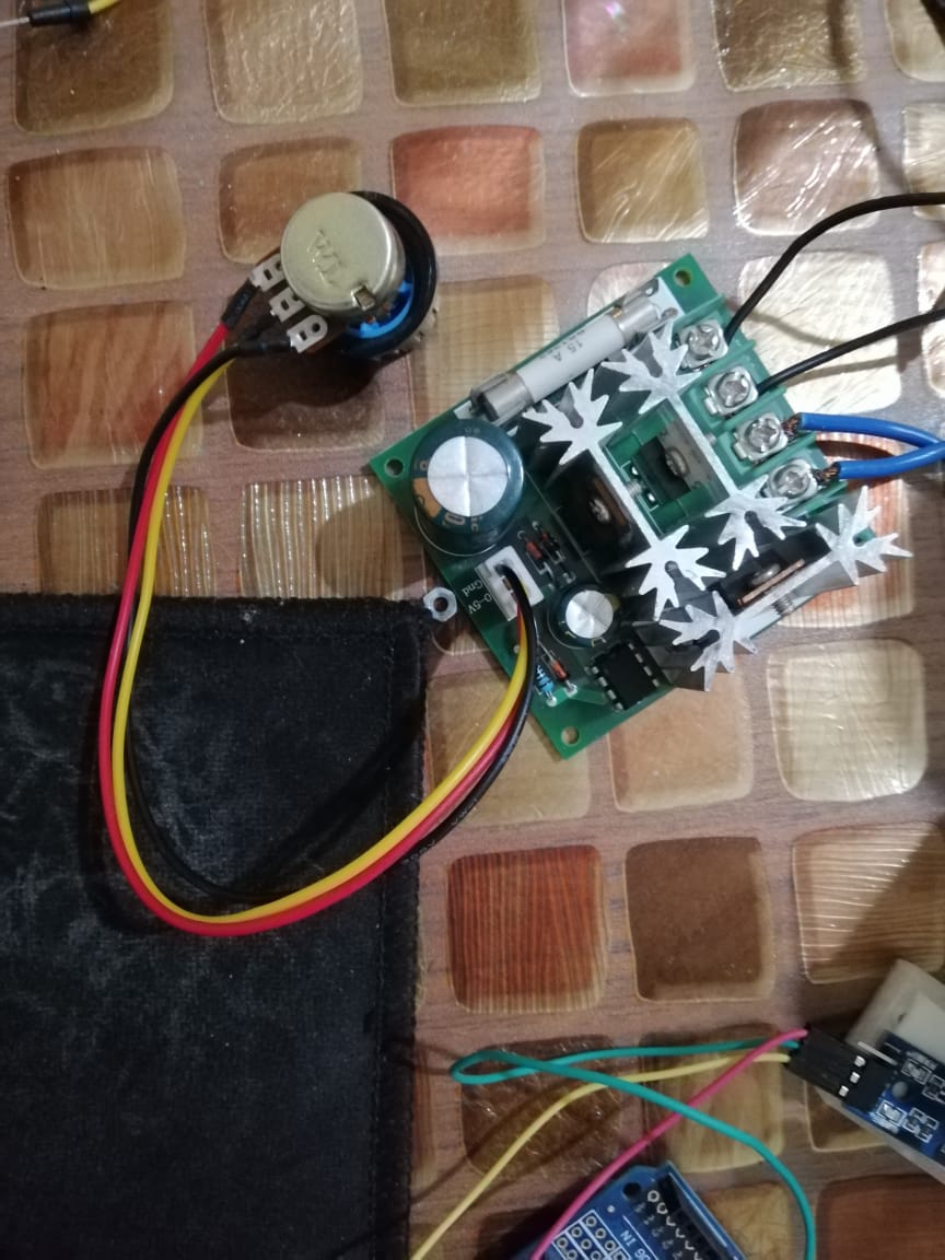
Motor is mounted with 12 teeth disk, that the Speed Encoder Sensor Module read it.
Hero shoot video:
The video shows that the data is send and translated to Tachometer gauge, and it will update in real time.
Temperature sensor reading
From week10, and after we had access to the lab again, I have used a NTC-NHQ103B375T10 THERMISTOR NTC 10KOHM, in a NTC Temperature bridge with three 10KOHM resistors.
NTC code:
This is the code to read and calculate the temperature sensor.
#include <SoftwareSerial.h>

const int rxPin = 0;
const int txPin = 1;
const int led = 7;  // Make sure that is the program is running
int R25 = 10000;        // Value of NTC at 25 degrees
int B = 3750;           // From NTC data sheet
int Vref = 0;           // Refrence voltage
int Vntc = 0;           // NTC voltage
double Intc = 0;        // NTC current
double Rntc = 0;        // NTC resistnace
double T = 0;

SoftwareSerial mySerial(rxPin, txPin); // Rx pin A0, Tx pin A1

void setup() {

  // define pin modes for tx, rx:
  pinMode(rxPin, INPUT);
  pinMode(txPin, OUTPUT);

  // Define the LED on board
  pinMode (led, OUTPUT);

  // Initialize Serial
  mySerial.begin(9600);
  delay(3000); // To see the message when open the monitor via FTDI cable
}

void loop() {
  // put your main code here, to run repeatedly:

  Vref = analogRead(2);   // Reads refrence voltage
  Vntc = analogRead(3);   // reads NTC voltagee

  // Calculating the current

  Intc = (2 * Vref) - Vntc;

  // Calculating the NTC resistance value

  Rntc = Vntc / Intc;

  T = ( 1 / (log(Rntc / R25) / B) + (1 / 298.15)) - 273.15;

  mySerial.println(T);

  delay(500);

}
Problem
When compile the program there is not enough storage space, so not to build a new board I decided to use Processing to compile the data.
Sketch uses 4292 bytes (104%) of program storage space. Maximum is 4096 bytes.

Global variables use 144 bytes (56%) of dynamic memory, leaving 112 bytes for local variables. Maximum is 256 bytes.
Sketch too big; see http://www.arduino.cc/en/Guide/Troubleshooting#size for tips on reducing it.
Error compiling for board ATtiny24/44/84.
New code for ATtiny44:
The new code for the ATtiny:
#include <SoftwareSerial.h>

const int rxPin = 0;
const int txPin = 1;
const int led = 7;  // Make sure that is the program is running
int R25 = 10000;        // Value of NTC at 25 degrees
int B = 3750;           // From NTC data sheet
int Vref = 0;           // Refrence voltage
int Vntc = 0;           // NTC voltage
double Intc = 0;        // NTC current
double Rntc = 0;        // NTC resistnace
double T = 0;

SoftwareSerial mySerial(rxPin, txPin); // Rx pin A0, Tx pin A1

void setup() {

  // define pin modes for tx, rx:
  pinMode(rxPin, INPUT);
  pinMode(txPin, OUTPUT);

  // Define the LED on board
  pinMode (led, OUTPUT);

  // Initialize Serial
  mySerial.begin(9600);
  delay(3000); // To see the message when open the monitor via FTDI cable
}

void loop() {
  // put your main code here, to run repeatedly:
  pinMode (led, LOW);
  Vref = analogRead(2);   // Reads refrence voltage
  Vntc = analogRead(3);   // reads NTC voltagee

// Sending data to Processing

  mySerial.println(Vref);
  mySerial.println(',');
  mySerial.println(Vntc);
  mySerial.println('.');

  pinMode (led, HIGH);
  delay(500);
Processing code
The program gets its values from the ATtiny44, and process it thought Serial event to read the values, then solve it by math equations from Neil’s code.
B = 3750.0
R25 =  10000.0
T = 1.0/(log(R/R25)/B+(1/(25.0+273.15))) - 273.15
And I created a window shows the value of the temperature in text, with little animation of red rectangular changes as the temperature changes.
import processing.serial.*;
import java.awt.event.KeyEvent; // imports library for reading the data from the serial port

Serial arduino;                      // Create object from Serial class

int Vref = 0;           // Reference voltage
int Vntc = 0;           // NTC voltage
String data1="";        // string to hold input
String data2="";
int index=0;

int R25 = 10000;        // Value of NTC at 25 degrees
int B = 3750;           // From NTC data sheet
float Intc = 0;        // NTC current
float Rntc = 0;        // NTC resistance
float Tempratue = 0;


void setup() {
  size(400, 400);
  background(255);

  printArray(Serial.list());
  arduino = new Serial(this, Serial.list()[0], 9600);
  arduino.bufferUntil('n');
  arduino.clear();                   // Throw out the first reading, in case we started reading
  delay(6000);
}

void draw() {

  clear();
  background(255);
  delay(50);
  // declare rect base
  fill(0, 0, 255);   // R,G,B
  rect(100, 150, 200, 100);

  // declare rect value
  fill(255, 0, 0);   // R,G,B
  rect(100, 150, (Tempratue*3.5), 100);

  //Temperature in text
  textSize(32);
  fill(0, 102, 153);
  text("Tempratue="+Tempratue, 100, 100);

}

void serialEvent(Serial arduino) {

  data1=arduino.readStringUntil('n');

  if (data1!=null) {
    data1= data1.substring(0, data1.length()-1);
    index= data1.indexOf("r");
    data2= data1.substring(0, index);
    data1= data1.substring(index+1, data1.length());

    // converts the String variables into Integer
    Vref= int(data2);
    Vntc= int(data1);

    float Intc1 = ((2 * Vref) - Vntc); //10000
    Intc= Intc1/10000;

    // Calculating the NTC resistance value

    Rntc = Vntc / Intc ;
    // Temperature = (1/((log(Rntc/R25))/B)+(1/298.15)) - 273.15 ;  //- 273.15
    float Temperature1 = 1/((log(Rntc/R25))/B+(1/298.15)) ;  //- 273.15
    Temperature= Temperature1 - 273.15;

    // Uncomment to see the values in console of processing
    //printArray("Vref="+Vref);
    //printArray("Vntc="+Vntc);
    //printArray("Intc1="+ Intc1);
    //printArray("Intc="+ Intc);
    //printArray("Rntc="+ Rntc);
    //printArray("Tempratue="+ Tempratue);
  }
}
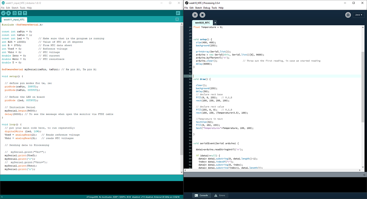
Arduino and Processing codes side by side:
Challenges:
- I had to break down the equations into two parts like:
Temperature1 and TemperatureandIntc1 and Intc, because for some reasons it does not give the correct values when I put the whole equations. - I added
clear();to refresh the screen, because each time the screen is being updated, the text overlaps with each other.
Hero shoot video! NTC temperature sensor
You can see the updated ATtiny board from week10 is connected to the NTC bridge board, also from the same week, to my laptop via FTDI cable to communicate to the Processing program that I have created.
The red bar slightly changes by the temperature is change, with numerical updated values