15. Networking and communications
This week we did not have access the lab, so I will update it later when it is done.
Download files:
Maste Writer/Slave Receiver modified
Bluetooth module Arduino UNO and I²C ATtiny
Assignment Objectives:
Individual assignment:
Design, build, and connect wired or wireless node(s) with network or bus addresses.
Group assignment:
Send a message between two projects
Group assignment
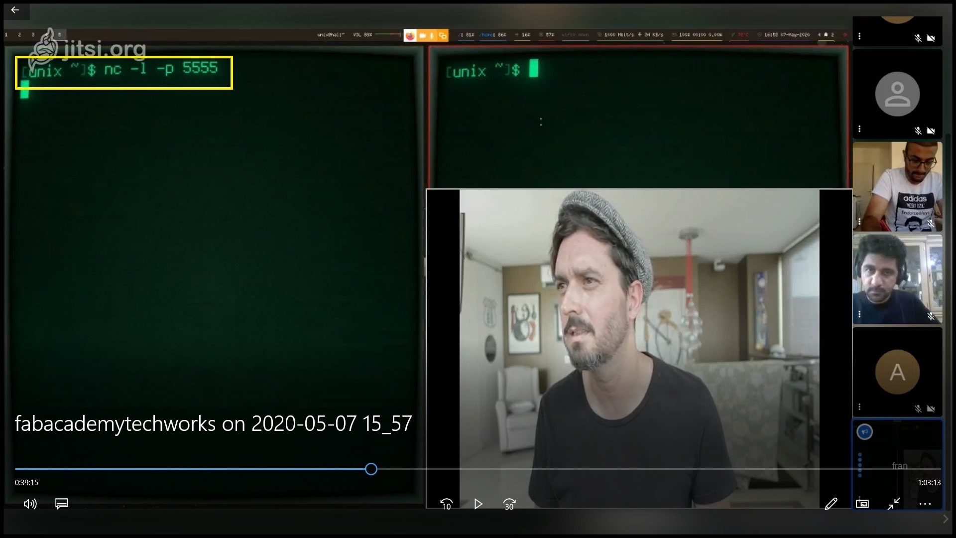
We complete the group assignment in a group call. Using Netcat (nc) under linux, we connected two PCs in two different locations, Frank in Spain with Faisal in Jordan. This is a simple and basic way to create communication beween two PCs to send and receive raw data.
Frank was using linux, Faisal was using Windows Subsystem for Linux.
Step 1: Frank opened a port in his PC terminal, the port number is 5555. He used the command nc -l -p 5555, l for listen and p for port. Now the terminal will be listening to port number 5555 in TCP protocol.
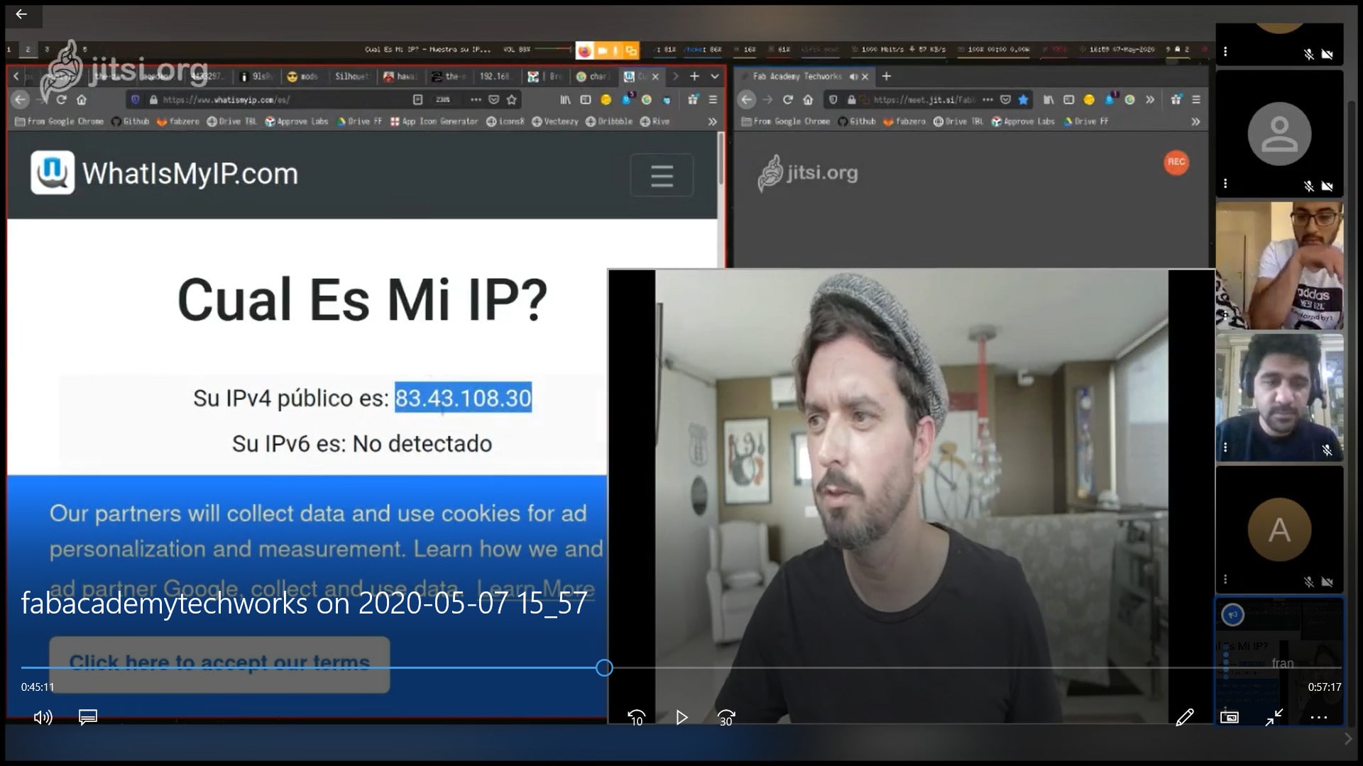
Step 2: Then Frank shared his IP address with Faisal. To open connection with Frank’s open port, Faisal used the command nc 83.43.108.30 5555. This command will communicate with port 5555 in the PC at address 83.43.108.30.
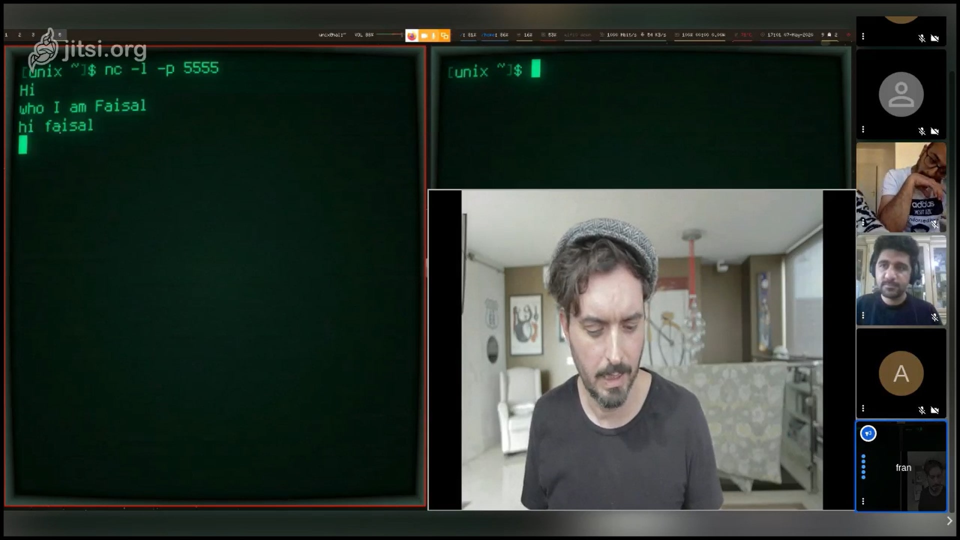
Step 3: Frank and Faisal had this conversation
Faisal: Hi
Frank: who
Faisal: I am Faisal
Frank: hi Faisal
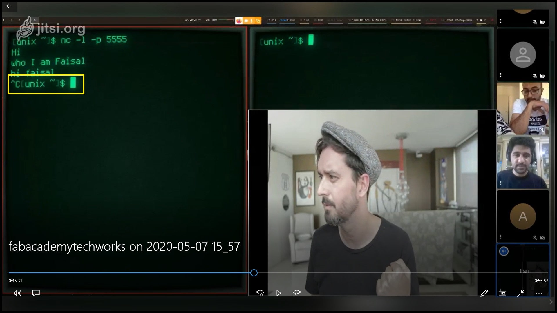
Step 4: To close the terminal port, Frank pressed “CTRL + C”. This will close communication between the terminals.
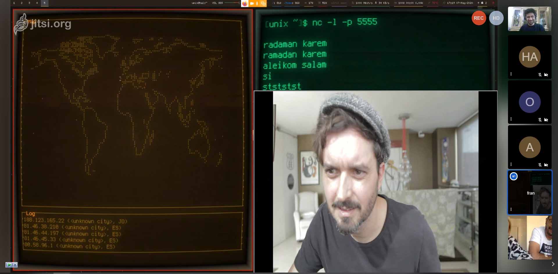
By using the traceroute then the IP address, you can see the path of packets across an IP network.
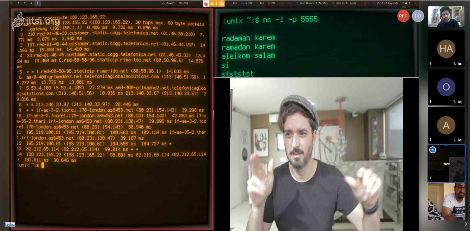
You can see a visual for traceroute by adding -iponmap ip on map after it.
Individual assignment
I have started with testing the I²C on a network made up from two Arduino UNO boards, from this Master Writer/Slave Receiver example from Arduino site, then build on it.
I have re-do the same program, but I changed the Master from Arduino to ATtiny 44, and used the library USIWire instead of Wire from Arduino, but they share the same functions.
I²C introduction
I²C (Inter-Integrated Circuit), pronounced I-squared-C, is a synchronous, multi-master, multi-slave, packet switched, single-ended, serial computer bus invented in 1982 by Philips Semiconductor (now NXP Semiconductors). It is widely used for attaching lower-speed peripheral ICs to processors and microcontrollers in short-distance, intra-board communication. Alternatively, I²C is spelled I2C (pronounced I-two-C) or IIC (pronounced I-I-C).
Applications
I²C is appropriate for peripherals where simplicity and low manufacturing cost are more important than speed. Common applications of the I²C bus are:
- Describing connectable devices via small ROM configuration tables to enable “plug and play” operation, such as:
- Serial Presence Detect (SPD) EEPROMs on dual in-line memory modules (DIMMs), and
- Extended Display Identification Data (EDID) for monitors via VGA, DVI and HDMI connectors.
- System management for PC systems via SMBus;
- SMBus pins are allocated in both Conventional PCI and PCI Express connectors.
- Accessing real-time clocks and NVRAM chips that keep user settings.
- Accessing low-speed DACs and ADCs.
- Changing contrast, hue, and color balance settings in monitors (via Display Data Channel).
- Changing sound volume in intelligent speakers.
- Controlling small (e.g. feature phone) OLED or LCD displays.
- Reading hardware monitors and diagnostic sensors, e.g. a fan’s speed.
- Turning on and turning off the power supply of system components.
A particular strength of I²C is the capability of a microcontroller to control a network of device chips with just two general-purpose I/O pins and software. Many other bus technologies used in similar applications, such as Serial Peripheral Interface Bus (SPI), require more pins and signals to connect multiple devices.
Design
I²C uses only two bidirectional open collector or open drain lines, Serial Data Line (SDA) and Serial Clock Line (SCL), pulled up with resistors. Typical voltages used are +5 V or +3.3 V, although systems with other voltages are permitted.
The I²C reference design has a 7-bit address space, with a rarely used 10-bit extension. Common I²C bus speeds are the 100 kbit/s standard mode and the 400 kbit/s Fast mode. There is also a 10 kbit/s low-speed mode, but arbitrarily low clock frequencies are also allowed. Recent revisions of I²C can host more nodes and run at faster speeds (400 kbit/s Fast mode, 1 Mbit/s Fast mode plus, 3.4 Mbit/s High Speed mode, and 5 Mbit/s Ultra Fast-mode). These speeds are more widely used on embedded systems than on PCs.

Master Writer/Slave Receiver
Explanation:
This circuit is a connection between two microcontrollers, two Arduino UNO, or my version is ATtiny and Arduino UNO, the master (ATtiny) from week07 is sending data of variable x, while x value start with zero, and increase by 1 each loop.
And the slave microcontroller will read the values and then print them into com port through USB serial communications.
The original code master_writer:
// Wire Master Writer
// by Nicholas Zambetti <http://www.zambetti.com>

// Demonstrates use of the Wire library
// Writes data to an I2C/TWI slave device
// Refer to the "Wire Slave Receiver" example for use with this

// Created 29 March 2006

// This example code is in the public domain.


#include <Wire.h>

void setup()
{
  Wire.begin(); // join i2c bus (address optional for master)
}

byte x = 0;

void loop()
{
  Wire.beginTransmission(4); // transmit to device #4
  Wire.write("x is ");        // sends five bytes
  Wire.write(x);              // sends one byte
  Wire.endTransmission();    // stop transmitting

  x++;
  delay(500);
}
The modified code:
As you can see I have used this line #include <USIWire.h> instead of #include <Wire.h>, and also for debugging I have added the #include <SoftwareSerial.h> to see if the using FTDI cable.
#include <USIWire.h>
#include <SoftwareSerial.h>

// for serial pins, FTDI
const int rxPin = 0;
const int txPin = 1;

//SoftwareSerial mySerial(rxPin, txPin); // RX, TX

void setup() {
  // put your setup code here, to run once:
  Wire.begin();
  delay(100);
  pinMode (3, OUTPUT);
  // define pin modes for tx, rx:
  //  pinMode(rxPin, INPUT);
  //  pinMode(txPin, OUTPUT);
  // Initialize Serial
  //  mySerial.begin(9600);
  //  delay(3000); // To see the message when open the monitor via FTDI cable
  //  mySerial.println("<Echo is ready>");
  digitalWrite(3, HIGH);
}

byte x = 0;

void loop() {
  // put your main code here, to run repeatedly:
  Wire.beginTransmission(4); // transmit to device #4
  Wire.write("x is ");        // sends five bytes
  Wire.write(x);              // sends one byte
  Wire.endTransmission();    // stop transmitting
  //  mySerial.println("x is");
  //  mySerial.println(x);

  x++;
  delay(500);
}
The slave_receiver code:
Where this microcontroller has the address #4.
// Wire Slave Receiver
// by Nicholas Zambetti <http://www.zambetti.com>

// Demonstrates use of the Wire library
// Receives data as an I2C/TWI slave device
// Refer to the "Wire Master Writer" example for use with this

// Created 29 March 2006

// This example code is in the public domain.


#include <Wire.h>

void setup()
{
  Wire.begin(4);                // join i2c bus with address #4
  Wire.onReceive(receiveEvent); // register event
  Serial.begin(9600);           // start serial for output
}

void loop()
{
  delay(100);
}

// function that executes whenever data is received from master
// this function is registered as an event, see setup()
void receiveEvent(int howMany)
{
  while(1 < Wire.available()) // loop through all but the last
  {
    char c = Wire.read(); // receive byte as a character
    Serial.print(c);         // print the character
  }
  int x = Wire.read();    // receive byte as an integer
  Serial.println(x);         // print the integer
}
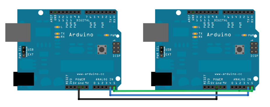
The circuit:
This show the orignal connection of the Master Writer/Slave Receiver example.
From the ATtiny 44 pinout we need to use the next pins:
- PA4 is SCL (Serial Clock)
- PA6 is SDA (Serila Data)
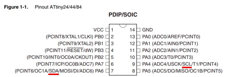
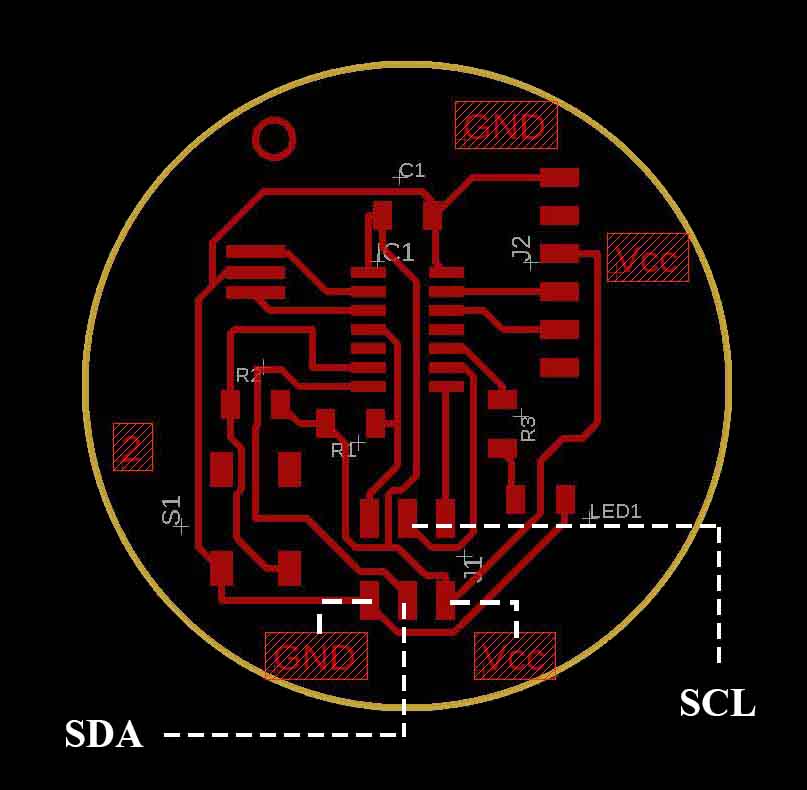
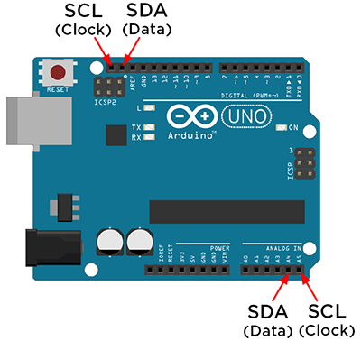
From the Arduino UNO pinout we need to use the next pins:
- A5 is SCL (Serial Clock)
- A4 is SDA (Serila Data)
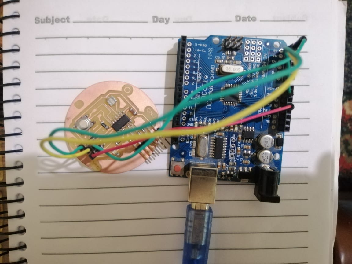
Wire connection between ATtiny44 and Arduino UNO.
Hero Shoot video:
Serial monitor shows the increment of x value for each new line.
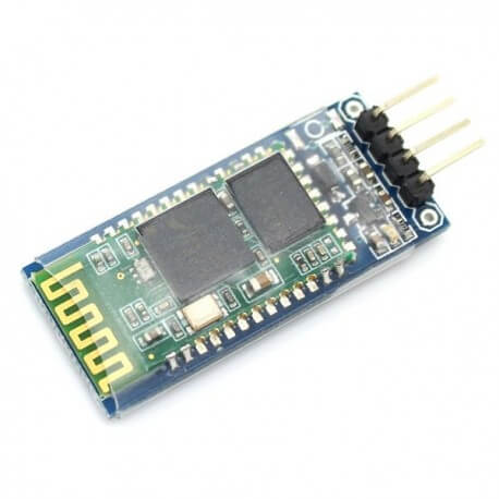
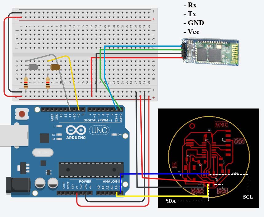
Bluetooth module, Arduino UNO, and I²C ATtiny
In this program, I changed the ATtiny44 to be slave in I²C connection, and Arduino is the master, in addition the Arduino is also connected to a Bluetooth module hc-06, and using Arduino Bluetooth Control on Google Play to send simple commands.
Part used in this project
- Arduino UNO
- ATtiny44 board with FTDI and SPI pins
- FTDI cable
- LED, x2
- 1K resistors, x2
- Bluetooth module hc-06
Circuit connections
- ATtiny44’s PA4 is SCL (Serial Clock) connected to Arduino’s A5
- ATtiny44’s PA6 is SDA (Serila Data) connected to Arduino’s A4
- Arduino’s Tx is connected to Bluetooth module Rx
- Arduino’s Rx is connected to Bluetooth module Tx
- ATtiny44’s Pin9 and Pin11 are connected to LED with 1K ohm resistors.
- Red wires are connected to Vcc
- Black wires are connected to GND
- ATtiny44 is connected to a computer by using FTDI cable
Codes and debugging
ATtiny44 code
In this code I have use the <SoftwareSerial.h> to send data to a computer by using FTDI cable, the send data shows the LED1 (L1) and LED2 (L2) state (ON/OFF).
Also you can see that I gave an address to the ATtiny44 Wire.begin(4);, that means ATtiny44 address is #4.
#include <USIWire.h>
#include <SoftwareSerial.h>

// for serial pins, FTDI
const int rxPin = 0;
const int txPin = 1;

SoftwareSerial mySerial(rxPin, txPin); // RX, TX

void setup() {
  // put your setup code here, to run once:
  Wire.begin(4);
  Wire.onReceive(receiveEvent); // register event
  delay(100);
  pinMode (3, OUTPUT);
  //   define pin modes for tx, rx:
  pinMode(rxPin, INPUT);
  pinMode(txPin, OUTPUT);
  //   Initialize Serial
  mySerial.begin(9600);
  delay(3000); // To see the message when open the monitor via FTDI cable
  mySerial.println("ATtiny44 is ready");
  digitalWrite(3, HIGH); // LED is on
  delay(5000);
}


void loop() {
  delay(100);
}

void receiveEvent(int howMany)
{
  while (1 < Wire.available()) // loop through all but the last
  {
    char c = Wire.read(); // receive byte as a character
    mySerial.print(c);         // print the character
  }
  mySerial.println(' ');
}
Arduino UNO code
- You can see in the code
Wire.begin(); // join i2c bus (address optional for master), define this is a master in I²C bus. void serialEvent()is to check if there are data incoming from the bluetooth module, and save it ininChar.if (stringComplete)ifstringCompletevalue isfalse, the code will ignor the code inside to have a faster loop.if (inChar == '1')is to check the incoming data from the Arduino Bluetooth Control app, and change the state of the LEDs.
#include <Wire.h>


bool stringComplete = false;  // whether the string is complete
char inChar = "";
int LED1 = 9;
int LED2 = 11;

void setup()
{
  Wire.begin(); // join i2c bus (address optional for master)
  Serial.begin(9600);           // start serial for output
  delay(8000);
  inputString.reserve(200);
  pinMode(LED1, OUTPUT);
  pinMode(LED2, OUTPUT);
  digitalWrite(LED1, LOW);
  digitalWrite(LED2, LOW);
  delay(3000);
  digitalWrite(LED1, HIGH);
  digitalWrite(LED2, HIGH);
  delay(5000);
  digitalWrite(LED1, LOW);
  digitalWrite(LED2, LOW);
  delay(1000);
}

void loop()
{

  if (stringComplete) {
    if (inChar == '1')
    {
      digitalWrite(LED1, LOW);
      digitalWrite(LED2, LOW);
      Wire.beginTransmission(4); // transmit to device #4
      Wire.write("L1 =");
      Wire.write(" 0");
      Wire.write('\n');
      delay(50);
      Wire.write("L2 =");
      Wire.write(" 0");
      Wire.write('\n');
      delay(50);
      Wire.endTransmission();    // stop transmitting
    } else if (inChar == '2')
    {
      digitalWrite(LED1, HIGH);
      digitalWrite(LED2, LOW);
      Wire.beginTransmission(4); // transmit to device #4
      Wire.write("L1 =");
      Wire.write(" 1");
      Wire.write('\n');
      delay(50);
      Wire.write("L2 =");
      Wire.write(" 0");
      Wire.write('\n');;
      delay(50);
      Wire.endTransmission();    // stop transmitting
    } else if (inChar == '3')
    {
      digitalWrite(LED1, LOW);
      digitalWrite(LED2, HIGH);
      Wire.beginTransmission(4); // transmit to device #4
      Wire.write("L1 =");
      Wire.write(" 0");
      Wire.write('\n');
      delay(50);
      Wire.write("L2 =");
      Wire.write(" 1");
      Wire.write('\n');
      delay(50);
      Wire.endTransmission();    // stop transmitting
    } else if (inChar == '4')
    {
      digitalWrite(LED1, HIGH);
      digitalWrite(LED2, HIGH);
      Wire.beginTransmission(4); // transmit to device #4
      Wire.write("L1 =");
      Wire.write(" 1");
      Wire.write('\n');
      delay(50);
      Wire.write("L2 =");
      Wire.write(" 1");
      Wire.write('\n');
      delay(50);
      Wire.endTransmission();    // stop transmitting
    }
  }


  // clear the string:
  inChar = "";
  stringComplete = false;
  delay(500);
}


void serialEvent() {
  while (Serial.available()) {
    // get the new byte:
    inChar = (char)Serial.read();
    // add it to the inputString:
    // if the incoming character is a newline, set a flag so the main loop can
    // do something about it:
    stringComplete = true;
  }
}
ATtiny44 debugging
- I had to reduce the data send to the computer, because the ATtiny has a small memory.
- I put
mySerial.println(' ');in the end of thevoid receiveEvent(int howMany)to seperate the next incoming data.
Arduino debugging
- I had to reduce the data send to the ATtiny, because the ATtiny had a problem to handle the incoming data; from
LED1 is HIGHtoL1 = 1. - I added
Wire.write('\n');to print new line in Arduino serial monitor. - To send the characters in
Wire.write( );you must put them between two quotation mark. - To send new line in
Wire.write('\n');you must put it between two apostrophes. - You can upload new programto the Arduino, if the Tx and Rx are connected, make sure that they are disconnected, or change Tx/Rx pins by using
#include <SoftwareSerial.h>, this library works on ATtiny and Arduino.
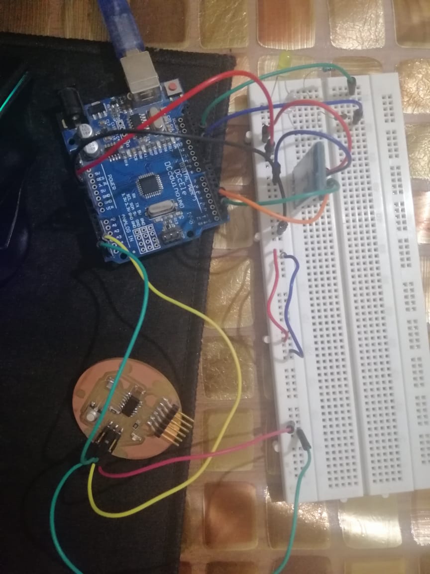
The circuit
Before connecting the FTDI cable, no power.
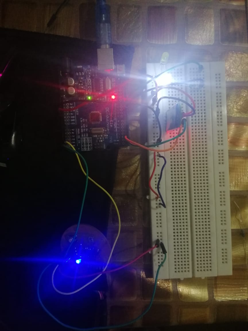
After connecting the FTDI cable, note that the usb cable of the Arduino is not connected.
Arduino Bluetooth Control app
This app let you send data to Arduino using a bluetooth module, I send mine from the buttons & Slider.
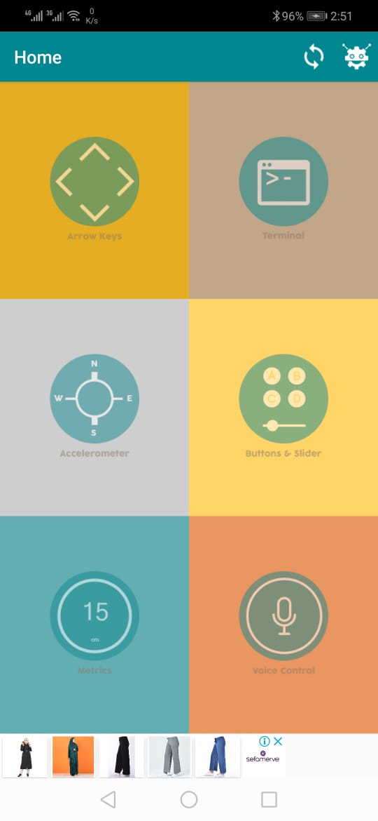
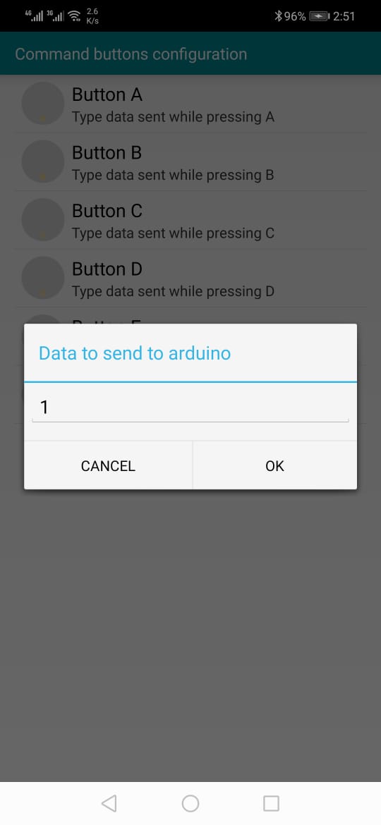
From the setting menu, you can see and configure buttons from the Command buttons configuration.
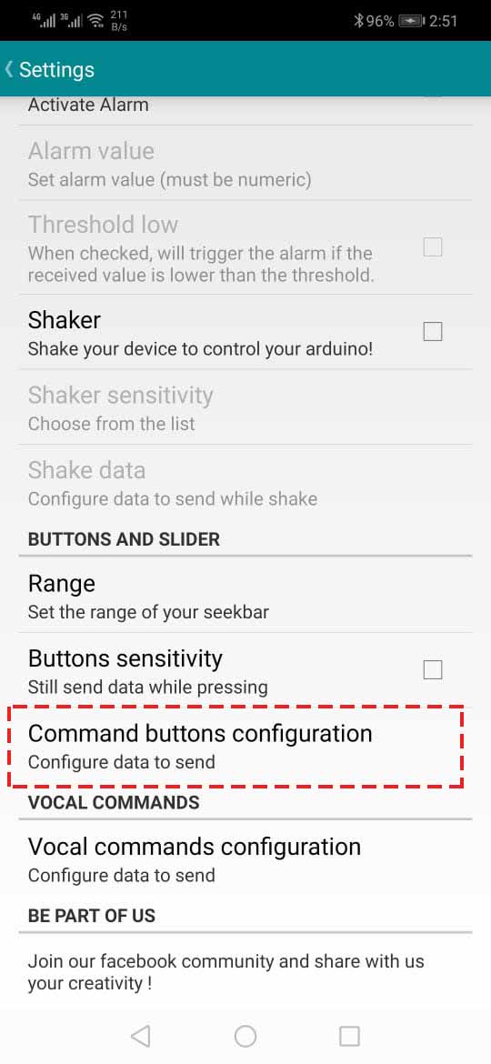
This the value of the button A.
Hero Shoot video:
This video shows:
- Controlling the LEDs from my phone.
- Sending data from Arduino to ATtiny44 using I²C, and data from the ATtiny to my laptop.